Advertisement
Available languages
Available languages
Quick Links
Advertisement
Chapters

Subscribe to Our Youtube Channel
Related Manuals for Rizzoli RTE Series


Summary of Contents for Rizzoli RTE Series
- Page 1 Istruzioni d’uso • Gebrauchsanweisung Instructions • Manuel d’utilisation...
-
Page 3: Table Of Contents
ITALIANO Disposizioni Installazione Impianto di riscaldamento Manutenzione Cosa fare se... Garanzia DEUTSCH Anweisungen Montage Heizungsanlage Gebrauch Wartung Was tun, wenn... Garantie ENGLISH Instructions Installation Heating system Use Maintenance What to do if... Warranty FRANÇAIS Avertissements Installation Installation de chauffage central Utilisation Entretien Que faire si... Garantie... -
Page 4: Disposizioni
Col tempo la Rizzoli ha continuato ad affinare le proprie casa una cucina a legna. cucine utilizzando tecnologie sempre più moderne ed La Vostra scelta è... - Page 5 COMBUSTIBILE RACCOMANDATO Le termocucine a legna sono espressamente co- evitare possibili deformazioni o danneggiamenti struite per la combustione di legna da ardere di della termocucina è consigliabile non inserire una qualsiasi tipo. Si consiglia di utilizzare legna di quantità eccessiva di legna (vedi scheda tecnica al- buona qualità, secca e ben stagionata; è preferibile legata). Bruciare un quantitativo eccessi v o di legna l’uso di legna spaccata. L’utilizzo di legna di buona può provocare l’improvviso incendio di gas infiam-...
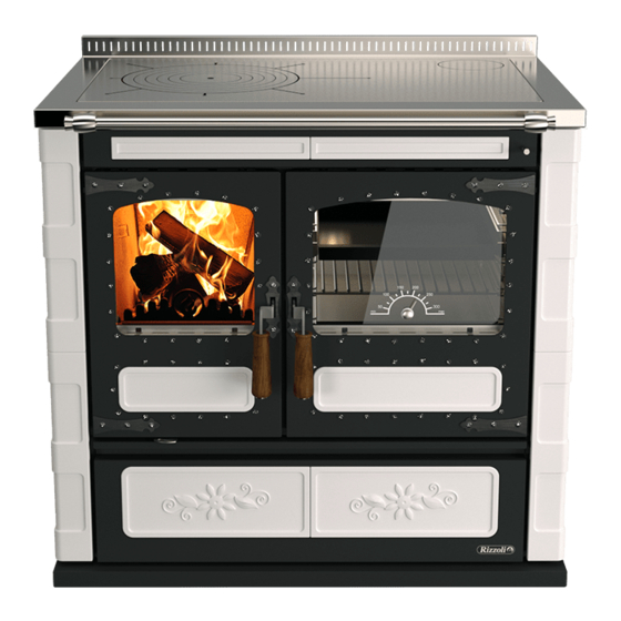
- Page 6 12 Leva di apertura porta 19 Termometro caldaia 6 Battifiamma 13 Cruscotto 20 Termometro forno 7 Zoccolo 14 Porta forno ACCESSORI In dotazione alle termocucine a legna Rizzoli sono lazione, la manutenzione e l’uso quotidiano. presenti alcuni accessori che semplificano l’instal- • Cassetto cenere • Dispositivi per il collegamento della uscita fumi • Guanto (serie RTVE) della termocucina, variabili in funzione del mo- • Attizzatoio dello e della uscita fumi prescelta • Raschietto (modelli con forno)
-
Page 7: Installazione
INSTALLAZIONE AVVERTENZE Le termocucine a legna Rizzoli sono di facile in- Va posta particolare attenzione al collegamento stallazione; vanno comunque osservate alcune con un impianto di riscaldamento idoneo e al colle- precauzioni per evitare danneggiamenti dovuti a gamento al camino, il quale deve essere adeguato imperizia. Prima dell’installazione raccomandiamo... - Page 8 CAMINO Il camino è di vitale importanza per il corretto fun- l’utilizzo di materiali adatti a resistere ad alta tem- zionamento di una termocucina a legna. Le termo- peratura e rispondenti alle norme antincendio, non cucine a legna sono studiate per garantire il mas- è fondamentale il tipo di materiale, purché adatto e simo rendimento, però le prestazioni offerte sono purché il camino sia ben isolato. molto influenzate dal funzionamento del camino. Consultate un tecnico specializzato oppure lo Nel caso in cui il camino presenti difetti o non ri- spazzacamino responsabile di zona per qualsiasi sponda alle norme tecniche di costruzione non è problematica riguardante camino, canna fumaria e garantito il corretto funzionamento della termocu- raccordo con la termocucina.
- Page 9 potrebbe portare a dei fenomeni di condensa e di no è inferiore a 4 metri non è garantito il corretto scarso tiraggio. In tabella 1 è indicato il diametro funzionamento della termocucina. Il camino non consigliato per la canna fumaria in funzione del deve avere tratti tortuosi, orizzontali o in contro- modello e dell’altezza del camino. L’altezza del ca- pendenza; il numero di curve deve essere ridotto al mino deve essere sufficiente a garantire il tiraggio minimo. In figura 5 sono evidenziati alcuni esempi necessario al modello prescelto. Più è alto il cami- di corretta e di scorretta realizzazione del camino. no e maggiore è il tiraggio, se l’altezza del cami- RTE 60 RTE 80 - RTVE 80...
- Page 10 RACCORDO O CANALE DA FUMO Il raccordo di collegamento tra la termocucina e la do non deve entrare all’interno della canna fuma- canna fumaria, detto anche canale da fumo, deve ria. Per rendere più sicuro il raccordo si consiglia di essere il più corto possibile e non deve presentare installare sul muro un rosone accertandosi che il tratti orizzontali o scarsamente inclinati. I tratti in collegamento fra rosone e camino sia ben murato contropendenza sono vietati e sono assolutamen-...
- Page 11 RTE 80 - RTE 90 - RTVE 80 - RTVE 90 Figura 8 – Termocucina multifumo con forno, predisposizione dell’uscita fumi corretta. Si riporta l’esempio con uscita fumi a destra. L’uscita fumi a sinistra è simmetrica. CORRETTO ALLACCIAMENTO AL CAMINO Se la canna fumaria parte dal piano inferiore ri- inserito e quindi girato in modo da restare bloc- spetto al punto di collegamento della termocucina cato. Questo connettore permette una tolleranza può essere necessario chiudere la canna fumaria di circa 1 cm in modo da facilitare l’installazione.
- Page 12 Figura 11 – Esempi di corretto e scorretto allacciamento alla canna fumaria. 2.10 USCITA FUMI POSTERIORE REGOLABILE (TERMOCUCINE CON FORNO) Tutti i modelli con forno presentano di serie la Su richiesta Rizzoli è in grado di fornire una lamie- possibilità di variare la posizione dell’uscita fumi ra aggiuntiva per poter utilizzare l’uscita fumi nelle posteriore. Lo spostamento si sviluppa sia oriz- posizioni intermedie. Sia per la regolazione in ver- zontalmente sia verticalmente, in modo da potersi ticale sia per quella in orizzontale si ha la tolleranza meglio adattare all’installazione del tubo di raccor- di 1 cm dell’attacco a baionetta, fornito in dotazio-...
- Page 13 LAMIERA STANDARD Modello standard RTE 80 - RTVE 80 RTE 90 - RTVE 90 Tabella 2a – Distanza minima e massima (in mm) del centro foro dell’uscita fumi. Non tiene in considerazione la tolleranza dovuta all’attacco a baionetta. Figura 12a – Vista posteriore della termocu- cina e rappresentazione dello spostamento minimo e massimo riguardo la posizione dell’uscita fumi posteriore con la lamiera standard. LAMIERA STANDARD CAPOVOLTA Modello standard RTE 80 - RTVE 80 RTE 90 - RTVE 90 Tabella 2b – Distanza minima e massima (in mm) del centro foro dell’uscita fumi. Non tiene in considerazione la tolleranza dovuta all’attacco a baionetta. Figura 12b – Vista posteriore della termocu- cina e rappresentazione dello spostamento minimo e massimo riguardo la posizione dell’uscita fumi posteriore con la lamiera standard capovolta.
- Page 14 Per fare questo è necessario La presa d’aria del locale deve avere una superficie predisporre un condotto collegato direttamente minima di 80 cm². con l’esterno dell’abitazione e effettuarne il col- Su richiesta Rizzoli può fornire delle valvole stu- legamento diretto con la presa d’aria della termo- Figura 13 – Installazione mediante presa d’aria nel locale e installazione con presa d’aria esterna collegata direttamente alla termocucina a legna.
- Page 15 Figura 14 – Modi di collegamento della presa d’aria della termocucina a legna. A= Presa aria esterna non colle- gata, B= Presa aria esterna a pavimento, C= Presa aria esterna a parete. Per semplificare il collegamento si consiglia di pre- cucina secondo specifiche variabili in funzione del disporre la presa d’aria esterna sul pavimento in modello (vedi tabella 3 e figura 15). Sono possibili corrispondenza dell’interno dello zoccolo, oppure altre soluzioni per il collegamento, ma vanno pre- a parete attraverso la parte posteriore della termo- ventivamente concordate con Rizzoli. ATTENZIONE! Cappe aspiranti o ventilatori di estrazione di aria del locale potrebbero causare problemi per il corretto funzionamento dell’apparecchio in mancanza di apposita presa d’aria o in caso di presa d’aria sottodimensionata. ø Modelli RTE 60 - RTVE 60 RTE 80 - RTVE 80 RTE 90 - RTVE 90 Tabella 3 - Misure per collegamento presa aria esterna Misure in mm Ingresso aria esterna Figura 15 – Vista posteriore dello zoccolo della ter-...
- Page 16 2.12 COLLEGAMENTI ELETTRICI (MODELLI CON FORNO) Il collegamento elettrico delle termocucine serve posta nel retro della termocucina. Devono essere unicamente per l’alimentazione della lampadina effettuati i corretti collegamenti di linea, neutro e del forno. L’allacciamento alla rete elettrica deve terra come indicato in figura 17. Il cavo e ogni altro essere effettuato da personale qualificato e se- dispositivo elettrico aggiunto deve essere dimen- condo le norme vigenti. L’installatore è responsa- sionato per il carico elettrico da sopportare e non bile del corretto collegamento in conformità alle deve toccare punti con temperatura superiore di norme di sicurezza. Per effettuare l’allacciamento 50 °C alla temperatura ambiente.
- Page 17 2.13 REGOLAZIONE DELLO ZOCCOLO Lo zoccolo delle termocucine è regolabile per adat- lo della termocucina tramite i piedini regolabili tarsi nel modo migliore all’ambiente in cui la ter- in altezza sia la regolazione della rientranza dello mocucina viene inserita. zoccolo rispetto al frontale. Per fare ciò occorre Per effettuare la regolazione dei piedini sulle ter- regolare singolarmente ciascun piedino presente mocucine si raccomanda di asportare la cassa por-...
- Page 18 2.14 PRIMA ACCENSIONE Prima dell’uso è necessario togliere i materiali di cina come verifica della corretta installazione. La imballaggio presenti nel forno e nella cassa porta prima accensione va effettuata con fuoco modera- legna, togliere le etichette adesive, togliere la pelli- to, con poca legna e spaccata in piccoli pezzi. Nelle cola di plastica in cui è avvolta la piastra e con uno accensioni successive si può aumentare progressi- straccio rimuovere la maggior parte dell’olio steso vamente il carico di combustibile. sulla superficie. Prima dell’accensione della termo- Nelle prime accensioni si potrebbero formare degli cucina è...
-
Page 19: Impianto Di Riscaldamento
IMPIANTO DI RISCALDAMENTO GENERALITÀ Le termocucine serie RTE - RTVE sono dotate di la normativa UNI 10683. Le termocucine sono do- caldaia per sfruttare il calore prodotto dall’appa- tate di tutte le predisposizioni necessarie per una recchio mediante un impianto con fluido vettore corretta installazione, ogni componente esterno per riscaldamento e produzione di acqua calda. Di alla termocucina (come pompe, valvole, termosta- norma l’impianto va progettato secondo la nor- ti, manometri, sistemi di allarme acustico e vaso di... - Page 20 RTE 80-90 - RTVE 80-90 con uscita fumi a destra 1) Attacco sonda termostato ausiliario (opzionale) ø ½” F 2) Attacco andata ø 1”¼ F 3) Bulbo per sonda di scarico termico (opzionale) ø ½” F 4) Attacchi per circuito di scarico termico (opzionale) ø ½” M 5) Attacco ritorno ø 1”¼ F 6) Attacco scarico ø ½” F 800/900 Figura 21 – Posizione degli attacchi caldaia per i modelli RTE 80, RTVE 80, RTE 90 e RTVE 90 con uscita fumi a destra (vista posteriore). Nei modelli con uscita fumi a sinistra la posizione è simmetrica. Prima della messa in funzione della termocucina è quindi in questi casi si possono tappare. Nella par- obbligatorio effettuare i collegamenti all’impianto te posteriore delle termocucine RTE - RTVE esiste di riscaldamento. L’utilizzazione della termocucina uno spazio utile di circa 35 mm tra gli attacchi e con la caldaia vuota o non collegata all’impianto la parete del locale di installazione.
- Page 21 RTE - RTVE con attacchi laterali 2) Attacco andata ø 1”¼ F 5) Attacco ritorno ø 1”¼ F 6) Attacco scarico ø ½” F 7) Attacco andata circuito di riscaldamento ø 1” F 8) Attacco ritorno circuito di riscaldamento ø 1” F Figura 22 – Posizione degli attacchi caldaia per i modelli RTE / RTVE con attacchi laterali (vista laterale). TIPI DI INSTALLAZIONE La normativa tecnica UNI 10412-2 ha introdotto stallate con impianto a vaso aperto, in questo caso la possibilità di installare gli apparecchi di riscal- va utilizzato il connettore di andata per collegare damento a combustibile solido abbinati a impian- anche il tubo di sicurezza e il connettore di ritorno...
- Page 22 La rea- dopo il montaggio per la manutenzione e la verifi- lizzazione dell’impianto di scarico termico è a cura ca funzionale. Deve essere eseguito il controllo del e sotto la responsabilità dell’installatore. Per realiz- funzionamento ad intervalli regolari. Si consiglia al- zare questo impianto ausiliario è necessario effet- meno una volta all’anno. Il circuito di scarico termi- tuare i collegamenti di andata e ritorno, che sono co non deve essere utilizzato per la produzione di interscambiabili, la sonda di comando dell’impian- acqua calda ad uso domestico. Su richiesta Rizzoli to deve essere inserita nell’apposito bulbo di colle- può fornire una valvola di scarico termico adatta gamento. L’impianto per essere efficace deve poter per l’impiego nelle proprie termocucine. Valvola di Sonda sensore Valvola riduzione di sicurezza pressione...
- Page 23 Figura 24 –Esempio di impianto con termocucina come generatore di calore.
- Page 24 Figura 25 –Esempio di impianto con termocucina come generatore di calore.
- Page 25 Figura 26 –Esempio di impianto con termocucina come generatore di calore.
- Page 26 Figura 27 –Esempio di impianto con termocucina con doppi attacchi (serie RTE - RTVE con attacchi laterali) come generatore di calore.
-
Page 27: Uso
FUNZIONAMENTO DELLA TERMOCUCINA Durante il funzionamento, all’interno della termo- stione avvenga in più punti diversi per ottenere la cucina avviene una reazione di combustione tra massima efficienza. In particolare è presente una il combustibile (la legna inserita nella camera di alimentazione di aria primaria, che affluisce nella combustione) e il comburente (l’ossigeno presente parte inferiore della camera di combustione attra- nell’aria dell’ambiente in cui è installata la termo- verso la griglia, e una o più alimentazioni di aria cucina). La termocucina realizza un tipo di combu- secondaria che affluiscono nella parte superiore stione intermittente: dopo avere acceso il fuoco... - Page 28 questo modo si ottiene un miglioramento del tirag- vigore si deve richiudere la chiave in modo da for- gio. Per accendere il fuoco potete utilizzare come zare il fumo a riscaldare tutte le parti della termo- combustibile legna ben secca, spaccata molto sot- cucina. La termocucina è progettata per l’utilizzo a tile, insieme ai prodotti specifici disponibili in com- chiave chiusa, utilizzarla con la chiave aperta non mercio. La combustione può essere difficoltosa consente alla termocucina di funzionare al massi- fino a quando non si è scaldato il camino.Il tempo mo delle sue capacità e può portare a surriscalda- necessario dipende dal camino e dalle condizio- mento con conseguenti danneggiamenti. ni meteorologiche.
- Page 29 Figura 29 – Regolazione della leva della presa d’aria. Figura 30 – Regolazione dell’aria primaria. Il regolato- La valvola è aperta in corrispondenza re si apre ruotando la manopola in senso della posizione indicata con la lettera “A”, orario. mentre è chiusa nella posizione indicata con la lettera “B”. ATTENZIONE! Per le termocucine RTVE, nel caricare la legna si raccomanda di mantene- re una distanza di alcuni centimetri tra il vetro interno della porta fuoco e il combustibile, in modo da non esporre il vetro a temperature eccessive che lo potrebbero danneggiare. REGOLAZIONE ARIA SECONDARIA L’aria secondaria è già regolata in modo da funzio- nare correttamente nelle condizioni di installazio- ni standard. Nel caso in cui si abbia un eccessivo accumulo di braci in camera di combustione o in generale sia necessario una maggiore quantità di aria primaria, è possibile utilizzare le due regola- zioni aggiuntive presente nel vano inferiore sotto il vano cenere, accessibile aprendo la portina (vedi...
- Page 30 REGOLAZIONE DELLA GRIGLIA Le termocucine sono dotate di griglia regolabile in altezza che permette di variare le dimensioni della camera di combustione a seconda delle esigenze dell’utilizzatore. La posizione più alta permette di avere la fiamma a diretto contatto con la piastra, è la posizione ideale per cucinare. La posizione più bassa invece permette di avere una camera di com- bustione più capiente e quindi di avere maggiore autonomia, è...
- Page 31 VALVOLA PER L’ECCESSO DI VAPORE (TERMOCUCINE CON FORNO) La cottura di pietanze in taluni casi può compor- tare la formazione di un eccesso di vapore all’in- terno del forno di cottura. Sui modelli con forno è presente una valvola per eliminare l’eccesso di vapore. La valvola è disposta all’interno del forno sulla parete laterale verso l’esterno e all’occorrenza va azionata in modo da aprire i fori di aerazione. Per evitare possibili scottature si raccomanda di azionare la valvola solo prima dell’accensione della termocucina.
- Page 32 4.10 ILLUMINAZIONE DEL FORNO (TERMOCUCINE CON FORNO) Nelle termocucine con forno è presente un im- pianto di illuminazione del forno stesso che, insie- me all’ampio vetro della porta, permette di control- lare a vista il procedimento della cottura nel forno senza dover aprire la porta. L’interruttore di accen- sione si trova estraendo la cassa porta legna su uno dei montanti laterali. Figura 35 – Interruttore per l’illuminazione del forno. 4.11 PORTA ACCESSORI (TERMOCUCINE CON FORNO) All’interno della cassa porta legna è presente un piccolo cassetto porta accessori che può esse- re molto utile per tenere in ordine gli oggetti più...
- Page 33 In dotazione alla termocucina è presente un dispo- di utilizzare delle presine o degli stracci. Il portate- sitivo portateglia che permette di estrarre la teglia glia va agganciato al bordo della teglia e utilizzato dal forno caldo in tutta sicurezza senza la necessità a due mani. 4.13 ESTRAZIONE CASSA PORTA LEGNA (TERMOCUCINE CON FORNO) Per la rimozione della cassa porta legna occorre re ed estrarre. Per rimettere in posizione la cassa estrarre la cassa fino a fine corsa, togliere le due porta legna ripetete le operazioni in senso inverso, viti a galletto che la tengono fissata alle strade prestando attenzione ad inserire correttamente la scorrevoli. Quando la cassa è libera si può solleva-...
-
Page 34: Manutenzione
Su richiesta Rizzoli fornisce degli specifici specifici per la pulizia dell’acciaio inox. Evitate di prodotti per la pulizia dell’acciaio inox. Per le par- utilizzare detersivi in polvere. Evitate assoluta- ti smaltate o verniciate evitate l’uso di abrasivi e... - Page 35 All’interno della camera di combustione della ter- cerchiata. mocucina a legna sono posizionate delle lamiere Successivamente è necessario togliere la piastra in mobili in acciaio che svolgono una duplice fun- modo da poter avere maggior spazio per eseguire zione: consentono l’entrata dell’aria secondaria di l’operazione. A questo punto si dovranno togliere postcombustione ad un’altezza ottimale per l’ab- le lamiere partendo dai lati della camera di com- battimento delle emissioni e proteggono l’integrità...
- Page 36 CASSETTO CENERE Tutte le volte che si utilizza la termocucina occorre to rendendo poi più laboriosa la pulizia. In caso di controllare il cassetto della cenere che si trova sot- accumulo eccessivo della cenere il fuoco potrebbe to la camera di combustione. Quando il cassetto è non essere alimentato in modo corretto e quindi pieno occorre svuotarlo. Se non viene svuotato la non si avrebbe una combustione regolare. cenere si accumula e potrebbe uscire dal casset- PULIZIA DEL FORNO (TERMOCUCINE CON FORNO) Il forno va pulito con i prodotti appositi disponibili dendola delicatamente e sollevando la parte bassa...
- Page 37 ATTENZIONE! Se la pulizia del camino non viene fatta come raccomandato ci può essere il pericolo di incendio della canna fumaria. PULIZIA DEI VETRI I vetri della porta del forno e, nei modelli serie bustione è stata studiata in modo da pulirsi da sola RTVE, della porta della camera di combustione si durante l’uso della termocucina. Ciò nonostante possono pulire con i normali prodotti specifici esi- di quando in quando potrebbe essere necessaria stenti in commercio. la pulizia del vetro a contatto con la fiamma della La parte interna della porta della camera di com- combustione.
- Page 38 una lampadina con le stesse caratteristiche tecni- pada. Di tanto in tanto è necessario effettuare la che (lampadina alogena 25W 230V 300 °C attacco pulizia del vetro coprilampada della lampadina del G9). forno. Per fare questo dovete svitare il coprilam- Per sostituire la lampadina occorre svitare il copri- pada, rimuovere i depositi esterni dovuti ai fumi di lampada, sfilare e rimuovere la lampadina, inserire cottura, lavare il coprilampada e dopo averlo ben la nuova lampadina e infine riavvitare il coprilam- asciugato riavvitarlo nella propria sede. Figura 43 – Smontaggio lampadina del forno. 5.12 DILATAZIONE TERMICA Durante l’uso tutti i materiali della termocucina trebbero causare delle deformazioni e anche delle sono soggetti a dilatazione e a piccoli movimenti...
-
Page 39: Cosa Fare Se
COSA FARE SE... Problemi Effetti Possibili rimedi • Verificare che tutte le regolazioni dell’aria siano nella loro posizione di massima apertura • Ve- rificare che cenere e residui non ostruiscano la griglia • Verificare che la griglia non sia montata alla rovescia (la parte piana va rivolta verso l’al- to) • Verificare che l’ambiente in cui è installata sia aerato a sufficienza e che non siano in fun- zione cappe aspiranti o altri dispositivi a combu- Combustione irregolare. stione • Verificare il corretto dimensionamento Combustione incompleta. del camino e dell’imbocco • Verificare che il Malfunzionamento Esce fumo dalla piastra. camino non sia ostruito e che sia stato pulito Esce fumo da altre parti della di recente • Verificare che non ci siano perdite termocucina. - Page 40 • Verificare la temperatura di attivazione della pompa di circolazione, non deve essere inferio- Si forma della condensa sulle pareti re a 55-60°C • In caso siano presenti dei grossi Condensa in camera di della caldaia, si forma uno strato serbatoi di accumulo di acqua calda, si consiglia di combustione di catrame o nerofumo difficile da installare una valvola o un sistema anti-condensa asportare • Verificare la corretta posizione delle lamiere in camera di combustione • Arieggiare preventivamente il locale • Aprire la chiave di avviamento • Utilizzare listelli di le-...
-
Page 41: Garanzia
(scontrino fiscale, di acquisto. Essa è valida solo per l’acquirente ini- fattura ecc.) e l’allegato cartellino di garanzia. Con- ziale e non è trasferibile. Affinché vengano prestati servateli con cura. i servizi in garanzia il cliente dovrà esibire un valido MODALITÀ DI GARANZIA La ditta Rizzoli si riserva, a proprio insindacabile Per le prestazioni in garanzia a domicilio il cliente giudizio, di scegliere l’azione più idonea per risol- è tenuto a corrispondere il diritto fisso di chiamata vere il problema oggetto di garanzia. Le parti difet- in vigore. Tale diritto non deve essere corrisposto tose sostituite restano di proprietà della ditta Riz- se la termocucina è stata acquistata da meno di 3 zoli. La ditta Rizzoli, a proprio insindacabile giudizio... - Page 42 Eventuali interventi al di fuori del periodo in ga- In questo caso verrà anche addebitato il costo dei ranzia o nei casi di non applicabilità della stessa pezzi sostituiti. verranno addebitati in base al tariffario in vigore. RESPONSABILITÀ La ditta Rizzoli non è responsabile per danni diretti rattere nazionale o locale o indicate nel presente o indiretti causati a persone o cose da difetti del libretto d’istruzioni. prodotto dovuti all’inosservanza delle norme a ca- TRIBUNALE COMPETENTE Per qualsiasi controversia o contestazione sarà com-...
- Page 43 INDICE DISPOSIZIONI pag. Disposizioni generali pag. Disposizioni di sicurezza pag. 1.3 Combustibile raccomandato pag. 1.4 Altri combustibili pag. 1.5 Componenti della termocucina pag. Accessori pag. INSTALLAZIONE pag. Avvertenze pag. Distanze di sicurezza pag. Camino pag. 2.4 Dimensioni e forme corrette del camino pag. Canna fumaria pag. Comignolo pag. 2.7 Raccordo o canale da fumo pag.
- Page 44 INDICE 4.7 Cottura nel forno (termocucine con forno) pag. 28 4.8 Valvola per l’eccesso di vapore (termocucine con forno) pag. 4.9 Teglia con guide scorrevoli (termocucine con forno) pag. 4.10 Illuminazione del forno (termocucine con forno) pag. 4.11 Porta accessori (termocucine con forno) pag. 4.12 Portateglia (termocucine con forno) pag. 4.13 Estrazione cassa porta legna (termocucine con forno) pag. 4.14 Protezione porta fuoco (optional) pag. 4.15 Copripiastra (optional) pag. MANUTENZIONE pag. Pulizia pag. 5.2 Pulizia delle parti a vista pag. 5.3 Manutenzione lamiere in camera di combustione pag. Pulizia della griglia pag.
-
Page 46: Anweisungen
Brennstoffe, die behagliche Wärme des natürlichen Feu- lung von Holzherden im typischen Stil der Dolomitentäler ers und der angenehme Duft des aus unseren Wäldern begann. Mit der Zeit hat Rizzoli seine Produkte durch den stammenden Holzes sind Argumente, die den Einsatz Einsatz modernster und zukunftsorientierter Technologi- eines Holzherdes nicht nur interessant, sondern aus en ständig verbessert, ohne jedoch die Eleganz, Schönheit... -
Page 47: Empfohlener Brennstoff
• Verwenden Sie nur Original-Ersatzteile oder sol- • Nehmen Sie keine Änderung am Zentralheizungs- che, die zugelassen sind. herd vor, die nicht autorisiert wurde. EMPFOHLENER BRENNSTOFF Rizzoli-Zentralheizungsherde sind ausdrücklich Verformungen oder Beschädigungen des Herdes zur Verwendung von Brennholz bestimmt. Es wird zu vermeiden, sollte auf keinen Fall übermäßig empfohlen, qualitativ gutes, luftgetrocknetes, viel Brennholz aufgelegt werden (siehe beigefüg- nach Möglichkeit gespaltenes Kleinholz zu ver-... -
Page 48: Zubehör
19 Thermometer Heizkessel 6 Flammenschutz 13 Reinigungsöffnung 20 Thermometer Backofen 7 Sockel 14 Backofentür ZUBEHÖR Im Lieferumfang der Rizzoli-Zentralheizungsherde tage, Wartung und den täglichen Gebrauch des sind einige Zubehörteile enthalten, die die Mon- Herdes erleichtern. • Aschekasten Herdes je nach Modell und gewähltem Rau- • Schutzhandschuh (Serie RTVE) chausgang • Schürhaken... -
Page 49: Montage
50 cm an der Vorderseite und 30 cm seitlich der technisches Datenblatt). Die entsprechenden Ab- Tür vorzusehen. Vom Einbau eines Hängeschranks standsverbindungen zur Lösung eventueller Prob- über dem Herd wird abgeraten. Auf jeden Fall muss leme werden auf Anfrage von Rizzoli geliefert. Falls dessen Hitzebeständigkeit garantiert und ein Min- der Herd zwischen nicht wärmeempfindlichen Ma- destabstand von 60 cm zur Herdplatte eingehalten terialien eingebaut wird, ist ein Mindestsicherheits- werden. -
Page 50: Rauchabzug
Der Rauchabzug ist von lebenswichtiger Bedeu- Rauchabzugs sind hochtemperaturbeständige tung für den einwandfreien Betrieb eines Zent- Baumaterialien, die den Brandschutzvorschriften ralheizungsherdes. Rizzoli-Zentralheizungsherde entsprechen, vorgeschrieben. Die Art der Werk- sind auf höchste Leistung ausgelegt, wobei diese stoffe spielt eine untergeordnete Rolle, sofern sie jedoch stark vom Verhalten des Rauchabzugs be- geeignet sind und der Rauchabzug gut isoliert ist. -
Page 51: Rauchabzugrohr
muss so dimensioniert sein, dass der Rauch ohne gewählte Herdmodell garantiert wird. Je höher der Schwierigkeiten aus dem Herd abziehen kann. Bei Rauchabzug, desto besser ist der Rauchzug. Bei Überdimensionierung würde sich der Rauchabzug einer Höhe unter 4 Metern ist ein einwandfreier nicht schnell genug erwärmen, was Kondenswas- Betrieb des Herdes nicht gewährleistet. Abgas- serbildung sowie schlechten Rauchzug zur Folge rohre dürfen keine gewundenen oder waagrech- haben könnte. In Tabelle 1 ist der empfohlene ten Abschnitte aufweisen und müssen immer mit... -
Page 52: Anschluss- Oder Rauchrohrstutzen
2.7 ANSCHLUSS- ODER RAUCHROHRSTUTZEN Der Anschlussstutzen zwischen Zentralheizungs- werden, dass er nicht in den freien Querschnitt hi- herd und Rauchabzug, auch Rauchrohrstutzen ge- neinragt. Zur höheren Sicherheit empfiehlt es sich, nannt, muss so kurz wie möglich gehalten werden eine Rohrmanschette anzubringen; dabei muss si- und darf keine waagrechten oder leicht geneigten chergestellt werden, dass der Anschluss zwischen Abschnitte aufweisen. Nach unten führende Ab- Manschette und Rauchabzug gut vermauert und schnitte sind nicht gestattet und absolut zu ver- abgedichtet ist. -
Page 53: Richtiger Anschluss An Den Rauchabzug
RTE 80 - RTE 90 - RTVE 80 - RTVE 90 Abb. 8 - Mehrfachanschluss - Zentralheizungsherd mit Backofen - korrekte Vorbereitung für den Anschluss. Beispiel mit Rauchausgang rechts. Der Rauchausgang auf der linken Seite ist symmetrisch. RICHTIGER ANSCHLUSS AN DEN RAUCHABZUG Falls das Rauchabzugsrohr unter der Anschluss- schluss verwendet werden. Um den Anschluss- stelle des Zentralheizungsherdes beginnt, kann stutzen in der richtigen Position zu fixieren, wird es erforderlich sein, ihn unterhalb des Rauchrohr- er eingeführt und bis zum Anschlag gedreht. -
Page 54: Regulierbarer Rauchausgang Auf Der Rückseite (Zentr. Mit Backofen)
Abb. 11 - Beispiele für den richtigen und falschen Anschluss an das Rauchabzugsrohr. 2.10 REGULIERBARER RAUCHAUSGANG AUF DER RÜCKSEITE (ZENTRALHEIZUNGSHERDE MIT BACKOFEN) Bei allen Modellen mit Backofen ist es serienmäßig ge kann Rizzoli eine zusätzliche Anschlussplatte möglich, die Position des Rauchausgangs auf der mit Rauchausgang in den mittleren Positionen Rückseite zu verändern. Dieser kann horizontal liefern. Für die horizontale und vertikale Regulie- und vertikal verstellt werden, um sich bestmög-... - Page 55 STANDARD-ANSCHLUSSPLATTE Modelle standard RTE 80 - RTVE 80 RTE 90 - RTVE 90 Tabelle 2a - Mindest- und Maximalabstand (in mm) ab Rauchausgangs-Mitte ohne Berücksichtigung der Toleranz des Anschlussstutzens mit Bajonettver- schluss. Abb. 12a - Rückansicht des Zentralhei- zungsherdes und Darstellung der min. und max. Verschiebung des Rauchausgangs auf der Rückseite mit der Standard-Anschlussplatte. UMGEDREHTE STANDARD-ANSCHLUSSPLATTE Modelle standard RTE 80 - RTVE 80 RTE 90 - RTVE 90 Tabelle 2b - Mindest- und Maximalabstand (in mm) ab Rauchausgangs-Mitte ohne Berücksichtigung der Toleranz des Anschlussstutzens mit Bajonettver- schluss. Abb. 12b - Rückansicht des Zentralhei- zungsherdes und Darstellung der min. und max. Verschiebung des Rauchausgangs auf der Rückseite mit der umgedrehten Standard- Anschlussplatte.
-
Page 56: Frischluftzufuhr
2.11 FRISCHLUFTZUFUHR Beim traditionellen Einbau des Zentralheizungs- liefert Rizzoli eigens hierzu entwickelte Lüftungs- herdes erfolgt die Luftzufuhr direkt aus dem klappen, die sich nur während des Betriebes des Aufstellungsraum über die Luftzufuhröffnungen Zentralheizungsherdes automatisch öffnen, um des Herdes im Inneren des Sockels. In diesem einen maximalen Unterdruck von 4 Pa im Aufstel- Falle muss im Raum stets für eine ausreichende... - Page 57 Um den Anschluss zu erleichtern, empfiehlt es Abb. 15), vorzunehmen. Weitere Anschlusslösun- sich, die externe Frischluftzufuhr entweder über gen sind nach vorheriger Absprache mit Rizzoli den Boden oder an der Rückwand des Herdes, in möglich. Sockelhöhe, je nach Modell (siehe Tabelle 3 und ACHTUNG! Dunstabzugshauben oder Lüftungsanlagen im Aufstellungsraum können ebenfalls die Funktionstüchtigkeit des Herdes bei fehlender, eigens dafür vorgesehener...
-
Page 58: Elektrische Anschlüsse (Modelle Mit Backofen)
2.12 ELEKTRISCHE ANSCHLÜSSE (MODELLE MIT BACKOFEN) Der elektrische Anschluss von Zentralheizungsher- Klemmbrett auf der Herdrückseite angeschlossen den dient ausschließlich zur Stromversorgung der werden. Alle Anschlüsse an die Stromversorgung Backofenlampe. Der Anschluss an die Stromver- (Phase, Neutralleiter und Schutzleiter) müssen wie sorgung muss von einem qualifizierten Fachmann in der Abbildung 17 ersichtlich, korrekt ausgeführt gemäß den geltenden Vorschriften vorgenommen werden. Das Kabel und jede andere zusätzliche werden. Der Installateur ist für den ordnungsge- elektrische Vorrichtung muss für die vorgesehene mäßen Anschluss in Übereinstimmung mit den Stromspannung ausgelegt sein und darf keine Stel- geltenden Sicherheitsbestimmungen verantwort- len berühren, die mehr als 50°C über der Umge-... -
Page 59: Einstellung Des Sockels
2.13 EINSTELLUNG DES SOCKELS Der Sockel der Zentralheizungsherde ist regulier- Es können sowohl der Sockeleinzug auf der Vor- bar, damit er bestmöglich dem Aufstellungsraum derseite als auch die Herdhöhe durch die Schraub- angepasst werden kann. Die Einstellung des So- füße eingestellt werden. Hierzu muss jeder einzel- ckels erfolgt im inneren Unterteil des Herdes. ne Schraubfuß in den Ecken des Sockels reguliert Hierzu muss die Holzlade entfernt werden und für werden, wodurch der Zentralheizungsherd gleich-... -
Page 60: Erste Inbetriebnahme
2.14 ERSTE INBETRIEBNAHME Vor der ersten Inbetriebnahme des Herdes muss sofort ein erstes Mal in Betrieb zu nehmen, damit jegliches Verpackungsmaterial aus dem Backofen seine ordnungsgemäße Installation kontrolliert und der Holzlade, eventuelle Klebeetiketten sowie werden kann. Das erste Anheizen des Herdes soll- die zum Schutz der Herdplatte verwendete Plas- te bei mäßigem Feuer und nur geringer Menge an tikfolie entfernt werden. Anhand eines Lappens kleinem Scheitholz erfolgen. Erst bei den nächsten beseitigen Sie den größten Teil des auf der Plat- Inbetriebnahmen kann die Beladung progressiv er-... -
Page 61: Heizungsanlage
HEIZUNGSANLAGE ALLGEMEINES Die Zentralheizungsherde Modelle RTE und RTVE nischen Bestimmung UNI 10683 installiert. Im Lie- sind mit einem Heizkessel ausgestattet, damit die ferumfang der Zentralheizungsherde sind alle für vom Gerät erzeugte Wärme für die Heizungsan- die ordnungsgemäße Installation nötigen Bauteile lage und die Warmbrauchwasseraufbereitung ge- enthalten. Alle externen Anschlusselemente des nutzt werden kann. In der Regel wird die Anlage Zentralheizungsherdes (wie z.B. Pumpen, Ventile, gemäß der italienischen UNI-Norm 10412-2 von Thermostat, Manometer, akustische Anzeigen und einem hierzu berechtigten Heizungstechniker ge- Ausdehnungsgefäß) müssen hingegen von Drittlie-... -
Page 62: Seitliche Anschlüsse
Modelle Serie RTE 80-90 / RTVE 80-90 mit Rauchausgang rechts 1) Anschluss für Thermostatfühler (Optional) Ø ½“ Innengewinde 2) Zulaufanschluss Ø 1“¼ Innengewin- 3) Muffe für Fühler Sicherheitswär- metauscher (Optional) Ø ½“ Innen- gewinde 4) Anschlüsse für Kreislauf Sicherheit- swärmetauscher (Optional) Ø ½“ Außengewinde 5) Rücklaufanschluss Ø 1“ ¼ Innengewinde 6) Ablaufanschluss Ø ½“ Innengewinde 800/900 Abb. 21 - Anschlussschema der Modelle RTE 80, RTVE 80, RTE 90 und RTVE 90 mit Rauchausgang rechts (Rückansicht). Bei Modellen mit Rauchausgang links befinden sich die Anschlüsse symmetrisch. Vor der Inbetriebnahme des Zentralheizungs- auf der Rückseite der Zentralheizungsherde RTE - herdes muss dieser an die Heizungsanlage ange- RTVE, zwischen den Anschlüssen und der Wand schlossen werden. Bei Gebrauch des Zentralhei- des Aufstellungsraums, beträgt ca. -
Page 63: Installationsmöglichkeiten
Modelle Serie RTE / RTVE mit seitlichen Anschlüssen 2) Zulaufanschluss Ø 1“ ¼ Innengewinde 5) Rücklaufanschluss Ø 1“ ¼ Innengewinde 6) Ablaufanschluss Ø ½“ Innengewinde 7) Zulaufanschluss Heizkreislauf Ø 1“ Innengewinde 8) Rücklaufanschluss Heizkreislauf Ø 1“ Innengewinde Abb. 22 - Anschlussschema der Modelle RTE / RTVE mit seitlichen Anschlüssen (Seitenansicht). INSTALLATIONSMÖGLICHKEITEN Die technische, italienische Norm UNI 10412-2 mit offenem Ausdehnungsgefäß installiert werden. sieht die Möglichkeit zur Installation von Zen- In diesem Falle muss der Zulaufanschluss auch für tralheizungsherden mit Festbrennstoffbetrieb die Verbindung mit dem Sicherheitsrohr und der in Kombination mit Anlagen mit geschlossenem Rücklaufanschluss auch für die Verbindung mit Ausdehnungsgefäß... -
Page 64: Sicherheit
Sicherheitswärmetauscher darf nicht für teile dieser Anlage müssen von Drittlieferanten die Warmbrauchwasseraufbereitung verwendet nach Angaben des Planers oder Installateurs der werden. Bei Bedarf kann Rizzoli ein passendes Anlage erworben werden. Zur Ausführung dieser thermisches Ablaufventil für Ihr Gerät liefern. Hilfsanlage müssen die austauschbaren Zu- und Fühler... - Page 65 Abb. 24 –Beispiel einer Heizungsanlage mit Zentralheizungsherd als Wärmeerzeuger.
- Page 66 Abb. 25 –Beispiel einer Heizungsanlage mit Zentralheizungsherd als Wärmeerzeuger.
- Page 67 Abb. 26 –Beispiel einer Heizungsanlage mit Zentralheizungsherd als Wärmeerzeuger.
- Page 68 Abb. 27 - Beispiel einer Heizungsanlage mit Zentralheizungsherd mit doppelten Anschlüssen (Serie RTE-RTVE mit seitlichen Anschlüssen) als Wärmeerzeuger.
-
Page 69: Gebrauch
GEBRAUCH BETRIEB DES ZENTRALHEIZUNGSHERDES Während des Betriebs erfolgt im Herd ein Ver- um ein Maximum an Effizienz zu erreichen. Zu brennungsprozess zwischen dem Brennstoff (im diesem Zweck wird sowohl Primärluft, die in den Feuerraum geladenes Holz) und dem Sauerstoff- unteren Teil des Feuerraums durch den mit Holz träger (in der Luft des Aufstellungsraums enthal- belegten Feuerrost strömt, wie auch an einer oder tener Sauerstoff). Der Zentralheizungsherd führt... -
Page 70: Luftregulierung
mer und Rauchabzug hergestellt, wodurch der Zug er lebhaft brennt, muss man die Anheizklappe des Zentralheizungsherdes verbessert wird. Ver- schließen, damit sich die Wärme auf alle Teile des wenden Sie als Brennstoff gut getrocknetes, sehr Herdes verteilt. Der Herd ist für den Betrieb mit dünnes Scheitholz zusammen mit den im Handel geschlossener Anheizklappe ausgelegt. Bei Betrieb erhältlichen speziellen Zündhilfen. Solange sich mit offener Klappe sind Leistung und Heizkraft des der Schornstein nicht erwärmt hat, können Pro- Herdes eingeschränkt und dies kann zu Überhit- bleme bei der Verbrennung auftreten. Wie viel zung führen und daraus entstehende Schäden zur... -
Page 71: Sekundärluft-Regulierung
Abb. 29 - Einstellung der Frischluftzufuhr-Regulie- Abb. 30 - Einstellung der Primärluft. Durch das rung. Wenn sich der Hebel auf der Position Drehen im Uhrzeigersinn, öffnet sich die “A“ befindet, ist die Luftzufuhr offen. Regulierung. Auf der Position “B“ ist die Luftzufuhr geschlossen. ACHTUNG! Achten Sie darauf, dass beim Holz einlegen ein Abstand von einigen cm zwi- schen Innenscheibe der Feuerraumtür und Brennstoff bleibt, um das Glas nicht zu hohen Temperaturen auszusetzen, die es beschädigen könnten. SEKUNDÄRLUFT-REGULIERUNG Die Sekundärluft ist bereits so reguliert, dass sie unter Standardbedingungen korrekt funktioniert. Im Falle einer übermäßigen Ansammlung von Glut in der Brennkammer oder wenn eine erhöhte Pri- märluft erforderlich ist, ist es möglich die beiden zusätzlichen Regulierungen unterhalb des Asche- kasten einzustellen, die durch das Öffnen der un- teren Tür zugänglich sind (siehe Abb. 31). -
Page 72: Höhenverstellbarer Feuerrost
HÖHENVERSTELLBARER FEUERROST Zentralheizungsherde sind mit einem höhenver- stellbarem Feuerrost ausgestattet, mit dem man nach Bedarf jede gewünschte Füllraumhöhe im Inneren der Brennkammer einstellen kann. Ideal zum Kochen ist die oberste Position, da hier die Flamme direkten Kontakt zur Herdplatte hat. In der untersten Position hat man eine geräumigere Brennkammer und somit eine längere Brenndauer, wodurch der Raum länger warm gehalten werden... - Page 73 DAMPFABLEITUNGSVENTIL (ZENTRALHEIZUNGSHERDE MIT BACKOFEN) Beim Backen oder Braten gewisser Speisen kann es manchmal zu übermäßiger Dampfbildung im Inneren des Backofens kommen. Deshalb sind die Herde mit Backofen mit einem Dampfableitungs- ventil ausgestattet. Das Ventil befindet sich im In- nenraum des Backofens, vorne an der Seitenwand und kann bei Bedarf zum Öffnen der Belüftungs- schlitze betätigt werden. Greifen Sie nie in den heißen Backofen, die Betätigung des Ventils ist ausschließlich bei kaltem Herd vorzunehmen.
- Page 74 4.10 BACKOFENBELEUCHTUNG (ZENTRALHEIZUNGSHERDE MIT BACKOFEN) Zentralheizungsherde mit Backofen sind mit einer elektrischen Innenbeleuchtung und großem Back- ofen-Sichtfenster zur bequemen Kontrolle des Back- und Bratvorganges ausgestattet, ohne dass hierzu die Backofentür geöffnet werden muss. Der Lichtschalter befindet sich seitlich der Holzlade. Um ihn zu betätigen muss die Holzlade herausge- zogen werden. Abb. 35 - Lichtschalter der Backofen-Innenbeleuchtung. 4.11 ZUBEHÖRFACH (ZENTRALHEIZUNGSHERDE MIT BACKOFEN) Im Inneren der Holzlade befindet sich ein kleines Zubehörfach welches als praktische Ablage für kleine Teile, um diese getrennt vom Brennholz auf- zubewahren, dient. Abb. 36 - Im Inneren der Holzlade montiertes Zu- behörfach. 4.12 BACKBLECHHALTER (ZENTRALHEIZUNGSHERDE MIT BACKOFEN) Abb. 37 - Backblechalter.
- Page 75 Im Lieferumfang des Zentralheizungsherdes steht Backofen genommen werden kann. Der Halter ein Backblechhalter zur Verfügung, anhand dessen wird einfach am Rand des Backblechs angebracht - ohne Einsatz von Topflappen oder Tüchern, das und mit beiden Händen verwendet. Backblech sicher und problemlos aus dem heißen 4.13 ENTFERNUNG DER HOLZLADE (MODELLE MIT BACKOFEN) Zur Entfernung der Holzlade ist es notwendig, ausgehängt werden. Um die Holzlade wieder ein- diese bis zum Anschlag herauszuziehen und die zuführen, geht man in umgekehrter Reihenfolge beiden Flügelschrauben mit denen sie an den vor und stellt sicher, dass sie wieder korrekt in die...
-
Page 76: Wartung
Oxidationsschicht bildet. Auch in diesen Fällen neutralen Reinigungsmitteln oder- bei hartnäcki- wird durch eine gründliche Reinigung alles wieder gen Verschmutzungen - mit speziellen im Handel wie neu. Auf Anfrage liefert Rizzoli spezielle Edel- erhältlichen Edelstahlreinigern gereinigt. Verwen- stahlreiniger. Zur Reinigung von emaillierten oder den Sie aber nicht Reinigungspulver. Verwenden... - Page 77 Im Inneren der Brennkammer des Zentralheizungs- Herdplatte, damit man mehr Platz hat, diesen Vor- herdes befinden sich mobile Stahlplatten, die eine gang durchzuführen. Nun können zuerst die Metall- Doppelfunktion erfüllen: sie dienen zum Schutz zwi- platten von den Seitenwänden und als Letztes die schen Feuer und Heizkessel und sie ermöglichen auf hinteren Platten des Heizkessels herausgenommen einer optimalen Höhe den Einlass der Sekundärluft, werden, indem man sie nach obenhin anhebt und wodurch eine Reduzierung der Emissionen erzielt aushängt. Zum Einlegen der Metallplatten geht man wird. Für eine gründliche Reinigung von Ascherück-...
- Page 78 ASCHEKASTEN Vor jedem Gebrauch des Zentralheizungsherdes und sich damit die Reinigung aufwendiger gestal- muss der Aschekasten unter dem Feuerraum kon- ten könnte. Durch eine zu große Aschenansamm- trolliert werden. Falls er voll ist, muss er entleert lung könnte das Feuer nicht richtig gespeist wer- werden, da Asche aus dem Kasten herausfallen den und die Verbrennung wäre unregelmäßig. REINIGUNG DES BACKOFENS (MODELLE MIT BACKOFEN) Verwenden Sie für die Reinigung des Backofens spe- ausgehängt werden indem man sie vorsichtig wieder zifische, handelsübliche Reinigungsmittel. Bei Bedarf...
- Page 79 ACHTUNG! Bei unzureichender Rauchabzugreinigung besteht die Gefahr eines Schorn- steinbrandes REINIGUNG DER SICHTFENSTER Zur Reinigung der Sichtfenster der Backofen- und nigen sich während des Betriebes von selbst. Hin der Feuerraumtür der Modelle RTVE verwenden und wieder kann jedoch auch eine manuelle Rei- Sie die spezifischen, handelsüblichen Reinigungs- nigung der Scheibe, die direkten Kontakt mit dem mittel. Die Innenscheiben der Feuerraumtür rei- Feuer hat, notwendig sein. ACHTUNG! Die Reinigung der Sichtfenster darf nur erfolgen, wenn der Herd kalt ist, um einen Glasbruch zu vermeiden. 5.10 REINIGUNG UND PFLEGE DER HERDPLATTE Die Stahl-Herdplatte des Zentralheizungsherdes...
- Page 80 Ein Großteil der Herdbauteile kann problemlos Bei Anfragen bezüglich Zubehör oder Ersatzteile mit einem normalen Schraubenzieher abmontiert geben Sie immer die in der beigelegten Infobro- werden. Eventuelle Reparaturen oder Änderungen schüre „10 grüne Regeln“ angeführte Seriennum- sind schneller und preiswerter, wenn der entspre- mer des Herdes an. Diese finden Sie auch seitlich chende Herdbauteil direkt oder über einen Wie- der Holzlade auf dem Typenschild. derverkäufer an die Firma Rizzoli retourniert wird.
-
Page 81: Was Tun, Wenn
WAS TUN, WENN... Probleme Anzeichen Mögliche Lösungen • Kontrollieren, ob alle Luftregulierungen auf der höchsten Öffnungsstufe eingestellt sind • Kontrollieren, ob keine Asche und Verbren- nungsrückstände den Feuerrost verstopfen • Kontrollieren, ob der Feuerrost korrekt einge- legt wurde (der flache Teil gehört nach oben) • Kontrollieren, ob der Aufstellungsraum aus- reichend belüftet wird und dass keine Dunst- abzugshauben oder andere Feuerungsanlagen... - Page 82 • Überprüfung der Aktivierungstemperatur der Wärmepumpe, diese darf nicht unter 55-60 °C An den Wänden des Heizkessels liegen • Bei großen Speichertanks von Warm- Kondenswasser bildet sich Kondenswasser, es ent- wasser empfiehlt es sich eine Rücklaufanhe- in der Brennkammer steht eine Teerschicht oder schwer bung- oder system zu installieren • Überprü f en, entfernbarer Ruß. ob die Metallplatten in der Brennkammer kor- rekt positioniert sind • Vor dem Anheizen den Aufstellungsraum lüf- ten • Die Anheizklappe öffnen • Gut trockene, dünne Holzscheite verwenden • Handelsübli- Es kann kein Feuer entfacht Anheizen nicht möglich che Zündhilfen verwenden • Kontrollieren, ob...
-
Page 83: Garantie
Gerät beiliegenden Garantie- und kann nicht übertragen werden. Bei Inanspruch- schein (bitte sorgfältig aufbewahren) vorweisen. nahme von Garantieleistungen muss der Kunde GARANTIEBESTIMMUNGEN Die Firma Rizzoli behält sich das Recht vor, nach leistungen an Ort und Stelle wird dem Kunden die ihrem freien Ermessen die zur Lösung des Garan- zu diesem Zeitpunkt geltende Anfahrtspauscha- tiefalls am besten geeigneten Maßnahmen zu er- le verrechnet. Diese Pauschale entfällt, falls der greifen. Ausgetauschte Teile verbleiben im Besitz... - Page 84 Firma Rizzoli gen Gerichtsstand auszuwählen. das Recht vor, auch einen anderen Gerichtsstand Hinweis Die Firma Rizzoli GmbH ist stets um die Verbesserung seiner Erzeugnisse bemüht und behält sich deshalb das Recht vor, eventuelle Änderungen dieser Gebrauchsanweisung ohne Vorankündigung vorzunehmen.
- Page 85 INHALTSVERZEICHNIS ANWEISUNGEN 1.1 Allgemeine Anweisungen 1.2 Sicherheitshinweise 1.3 Empfohlener Brennstoff S. 1.4 Andere Brennstoffe S. 1.5 Herdbestandteile 1.6 Zubehör MONTAGE 2.1 Anweisungen 2.2 Sicherheitsabstände S. 2.3 Rauchabzug S. 2.4 Richtige Abmessungen und Formen des Rauchabzugs S. 2.5 Rauchabzugrohr 2.6 Schornsteinaufsatz 2.7 Anschluss- oder Rauchrohrstutzen S. 2.8 Rauchausgänge 2.9 Richtiger Anschluss an den Rauchabzug 2.10 Regulierbarer Rauchausgang auf der Rückseite (Zentr. mit Backofen) S.
- Page 86 INHALTSVERZEICHNIS 4.7 Backen und Braten im Backofen (Zentralheizungsherde mit Backofen) S. 4.8 Dampfableitungsventil (Zentralheizungsherde mit Backofen) 4.9 Backblech auf Teleskopschienen (Zentralheizungsherde mit Backofen) 4.10 Backofenbeleuchtung (Zentralheizungsherde mit Backofen) 4.11 Zubehörfach (Zentralheizungsherde mit Backofen) 4.12 Backblechhalter (Zentralheizungsherde mit Backofen) 4.13 Entfernung der Holzlade (Modelle mit Backofen) 4.14 Schutz der Feuerraumtür (optional) 4.15 Herdplattenabdeckung (optional) WARTUNG 5.1 Reinigung 5.2 Reinigung der sichtbaren Teile 5.3 Wartung der Metallplatten in der Brennkammer 5.4 Reinigung des Feuerrostes 5.5 Reinigung der Rauchgaszüge (Modelle mit Backofen) 5.6 Aschekasten 5.7 Reinigung des Backofens (Modelle mit Backofen) 5.8 Reinigung des Rauchabzugs 5.9 Reinigung der Sichtfenster 5.10 Reinigung und Pflege der Herdplatte 5.11 Wartung der Backofenbeleuchtung...
-
Page 88: Instructions
Year after year Rizzoli of our forests are the qualities that make indispensable continued to refine its thermal cookers using even more wood fired thermal cookers in every house. - Page 89 RECOMMENDED COMBUSTIBLES Wood fired cookers are built to use wood for burn- eventual deforming and damaging processes you ing. We recommend to use good quality wood, dry, must not use excessive combustible (see attached seasoned and possibly broken. sheet). Burning an excessive amount of wood can Using good quality wood is warranty of good heat- cause the sudden ignition of flammable gases, with ing power and avoid the forming of carbon resid- the risk of causing damage to things and people. uals and soot. To avoid dissipation of energy and WARNING! Painted parts of the thermal cooker may become discolored due to exces- sively high temperatures in the combustion chamber. The causes may be the addition of wood over the permitted amount or the use of unsuitable fuel. This damage is not covered by warranty.
- Page 90 RTVE 60 RTVE 80/RTVE 90 Picture 2 Riser Primary air regulator 15 Oven door glass Frame Air intake lever 16 Starting lever Side 10 Ash door 17 Plate Fire door 11 Woodbox 18 Disc or circles Fire door glass 12 Door opening lever 19 Boiler thermometer Flame keeper 13 Dashboard 20 Oven thermometer Plinth 14 Oven door ACCESSORIES Together with the wood fired thermal cookers you lation, the maintenance and the daily use of the will find some accessories that simplify the instal- device.
-
Page 91: Installation
The device must be placed on a roof with enough In case you want to use an aspiring hood, it is abso- load capacity. If the existing building does not sat- lutely necessary that it is resistant to high temper- isfy this condition, you must adopt different solu- atures. Rizzoli is specialized in the production of tions (for example you can use a plate to distribute aspiring hoods to be used together with the wood the load). fired thermal cookers. During the installation, you Before final positioning it is recommended to must be sure not to obstruct the ventilation holes... - Page 92 CHIMNEY Chimney has a main importance for the correct chimney you must use suitable materials, made working of a wood fired thermal cooker. Wood to work with high temperatures and according to fired thermal cookers are built to insure the max- fireproof laws: it is not important the kind of mate- imum efficiency, anyway the performances of rial, on condition that it is right and that the chim- the thermal cooker are deeply influenced by the ney is isolated. Consult a specialized technician or chimney. If the chimney has defects or does not the chimney sweeper in charge of the area for any...
- Page 93 problems in heating itself and this may generate the chimney, bigger is the draught; if the chimney problems like weak draught and condensation. In is lower than 4 metres, the correct working of the table 1 it is indicated the recommended diame- thermal cooker is not insured. The chimney must ter for the flue according to the model and to the not have tortuous parts, horizontal parts or coun- height of the chimney (H). The height of the chim- terslope parts; the number of bends must be re- ney must be enough to insure the draught neces- duced to minimum. In picture 5 you can see some sary to the chosen model. Bigger is the height of...
- Page 94 CONJUNCTION The conjunction of the thermal cooker to the flue not go inside the flue. To increase the safety of the must be as short as possible and must not have conjunction, we suggest to install a washer on the horizontal or not much inclined parts. The counter- wall being sure that the connection between the slope parts are forbidden and must be absolutely washer and the chimney is walled and well sealed. avoided. Near the conjunction, inflammable mate- Also the connection between the thermal cooker rials must not be present. The conjunction must and the conjunction must be fixed and sealed. FLUE OUTLET PREDISPOSITION Wood fired thermal cookers are predisposed to you will not use are well closed. Eventually, you have flue outlets in different positions (up, back, can make modifications using the devices given sides). Before connecting the thermal cooker to...
- Page 95 RTE 80 - RTE 90 - RTVE 80 - RTVE 90 Picture 8 – Multiflue thermal cooker with oven, predisposition of the correct flue outlet. In the example, ther- mal cooker with right flue outlet. The left flue outlet is symmetrical. CORRECT CONJUNCTION TO THE CHIMNEY If the conduct of the chimney starts from a low- must be inserted and turned so that it can remain er floor than the connection point of the thermal blocked. This connector has a tolerance of about 1 cooker, it may be necessary to close the conduct cm to make the installation easier. The tolerance under the connection pipe with fireproof materi-...
- Page 96 Picture 11 - Samples of correct and incorrect connection to the chimney hood. 2.10 ADJUSTABLE REAR FLUE OUTLET (THERMAL COOKERS WITH OVEN) On most models with oven it is possible to change On demand, Rizzoli can provide an extra sheet to the position of the rear flue outlet. The move- be used in the intermediate positions of the sheet. ment can be done both horizontally and vertical- For both the horizontal and the vertical regulations ly, in order to connect more easily the pipe to the there is a tolerance of 1 cm thanks to the provided chimney hood. For the horizontal regulation, it is...
- Page 97 STANDARD SHEET Model standard RTE 80 - RTVE 80 RTE 90 - RTVE 90 Table 2a – Minimum and maximum distances from the centre of the hole of the flue outlet. It is not considered the tolerance generated by the bayonet fitting. Picture 12a – Rear sight of the cooker and representation of the minimum and maximum movement of the rear flue outlet position with standard sheet. TILTED STANDARD SHEET Model standard RTE 80 - RTVE 80 RTE 90 - RTVE 90 Table 2b – Minimum and maximum distance from the centre of the hole with the extra sheet. It is not considered the tolerance generated by the bayonet fitting. Picture 12b – Rear sight of the cooker and representation of the mini- mum and maximum movement of the rear flue outlet position with tilted standard sheet.
- Page 98 80 cm2. On demand, Rizzoli In the models with oven, it is possible to access can give specific valves which can allow the auto- directly from the woodbox. For the connection, we matic opening of the air intake only when it is nec- suggest to use a flexible pipe.
- Page 99 (see table 3 and picture 15). Are also possible oth- ence with the internal part of the plinth, or on the er solutions for the connection but they must be wall through the rear part of the thermal cooker decided together with Rizzoli. WARNING! Aspiring hoods or extracting air fans in the room may generate problems to the device if there is not a suited air intake or in case of air intake sub-dimensioned. ø Model RTE 60 - RTVE 60 RTE 80 - RTVE 80...
- Page 100 2.12 ELECTRIC CONNECTIONS (THERMAL COOKERS WITH OVEN) The electric connection of the thermal cookers minal board placed in the rear side of the thermal gives power only to the oven lamp. The connec- cooker. Must be done the correct connections of tion to AC power must be done by experienced line, neutral and earth as described in picture 17. people and according with existing laws. The in- The cable and every other electric device added staller is responsible of the correct connection ac-...
- Page 101 2.13 PLINTH REGULATION The plinth of the thermal cookers can be regulated cooker by operating on the levelling pins that can in order to match the space in which the cooker be regulated in height and the recess of the plinth is inserted. To regulate the pins of the thermal to the front. To do this, it is necessary to regulate 0-20 cooker it is recommended to remove the woodbox singularly each pin placed in the plinth near the and to place the device laying on the rear side to corners, so that the adjustment of the cooker is have access on the lower part. For this operation...
- Page 102 2.14 FIRST LIGHTING Before starting to use the thermal cooker, re- the correct installation. The first lighting must be move the packaging materials in the oven and in done with moderate fire, using little wood broken the wood box, remove the stickers and remove in small pieces. In the next lightings you can pro- the plastic film in which is wrapped the plate and gressively increase the load of combustible. remove with a rag the most of the oil on its sur- During the first lightings some smell due to pro- face. Before lighting the thermal cooker, it must be cessing residuals might happen. This phenomenon...
-
Page 103: Heating System
HEATING SYSTEM GENERAL NOTES RTE and RTVE thermal cookers are endowed with isting laws in particular to UNI 10683:2005 law. boiler to use the heating produced by the device The thermal cookers are endowed with all the through a system with fluid vector for heating necessary predispositions for a correct installa- and for the production of hot water. The system tion, every external component (as pumps, valves, must be designed according to UNI 10412-2:2006 acoustic alarms, pressure switches) must be ob-... - Page 104 RTE 80-90 - RTVE 80-90 with flue outlet on the right side 1) Connection detector of auxiliary thermostat (optional) ø ½’’ female 2) Going connection ø 1’’¼ female 3) Bulb for thermal discharge detector (optional) ø ½’’ female 4) Connection for thermal discharge circuit (optional) ø ½’’ male 5) Return connection ø 1’’¼ female 6) Connection discharge ø ½ female 800/900 Picture 21 - Hydraulic connection scheme of a thermal cooker RTE 80, RTE 90, RTVE 80 and RTVE 90 with flue outlet on the right side (rear sight). The thermal cooker with flue outlet on the left side is symmetrical. Before the lighting of the thermal cooker it is nec- necessary and so in this case you can cover them. essary to make the connections to the heating In the rear part of RTE - RTVE thermal cookers system. The use of the thermal cooker with empty there is an useful space of 35 mm between the or not connected to the system boiler causes the...
- Page 105 RTE - RTVE with connections on the side 2) Going connection ø 1’’¼ female 5) Return connection ø 1’’¼ female 6) Return discharge ø ½’’ female 7) Going connection heating circuit ø 1’’ female 8) Return connection heating circuit ø 1’’female Picture 22 - Hydraulic connections scheme for RTE / RTVE models with connections on the side (lateral sight). INSTALLATION MODES The technical law (UNI 10412-2:2006) has intro- open expansion tank, in this case you should use duced the possibility to install the solid combus- the going connector to connect also the safety tion based devices matched with devices with pipe and the return connector also for the pipe of closed expansion tank, endowed with thermal dis- discharge.
- Page 106 On demand, Rizzoli can give a thermal discharge er. To make this auxiliary system it is necessary to valve appropriate for the use with its thermal make the going and return connections, that are cookers.
- Page 107 Picture 24 - Schemes for the installing of a heating system with the thermal cooker as heat generator.
- Page 108 Picture 25 - Schemes for the installing of a heating system with the thermal cooker as heat generator.
- Page 109 Picture 26 - Schemes for the installing of a heating system with the thermal cooker as heat generator.
- Page 110 Picture 27 – Schemes for the installing of a heating system (RTE - RTVE with connections on the side) with the thermal cooker with double fittings as a heat generator.
-
Page 111: Use
WORKING OF THE THERMAL COOKER During the working, inside the thermal cooker hap- wood requests that the air flow inside the combus- pens a combustive reaction of combustible (the tion chamber happens in different points to obtain wood inserted in the combustion chamber) and the maximum efficiency. In particular, it is present comburent (the oxygen present in the air of the a primary air feeding that flows in the lower part room in which the thermal cooker is placed). The of the combustion chamber by the grill, and one or wood fired thermal cooker makes an intermittent more secondary air feedings that flow in the upper combustion: after the lighting, the combustion part of the combustion chamber. The primary air is goes on till the exhaustion of the combustible but the main air and regulates the combustion speed. - Page 112 obtain a better draught. To light the fire, you can key in order to force the fume to heat the other use well dried wood, very subtly cut, together with parts of the thermal cooker. The thermal cooker is the specific products you can find in commerce. designed to work with the key turned off, the use The combustion may be difficult as long as the with the key opened does not allow the thermal chimney is cold. The necessary time depends on cooker to work at its best and may cause overheat- the chimney and on the weather conditions. When...
- Page 113 Picture 29 – Regulation of the air intake lever. The Picture 30 – Regulation of primary and secondary valve is open in correspondence of the air. The regulator opens rolling the hand position indicated by letter “A” while it grip clockwise. is closed in the position indicated with letter “B”. WARNING! On RTVE thermal cookers,when loading wood, it is recommended to keep a distance of some centimetres between the fire door and the combustible, in order to not expose the glass to high temperatures that could damage it. SECONDARY AIR REGULATION The secondary air is already set to work correctly in standard installation conditions. When inside the combustion chamber of thermal cooker LT range an excessive accumulation of embers hap- pens or gen e rally it is necessary a bigger quantity of primary air, it is possible to use the two addicti- ve regulations located in the lower vain below the...
- Page 114 GRILL REGULATION The thermal cookers are endowed with an height adjustable grill which allows to adjust the com- bustion chamber’s dimensions according to user’s needs. The upper position allows to have the flame in direct contact with the plate, it is the best posi- tion for cooking. The lower position instead allows to have a more capacious combustion chamber and so to have more autonomy, it is the best solu- tion to keep the room warm for a longer time. The grill must be regulated with cold thermal cooker using the special tool given together with the ther- mal cooker, the connection point to regulate it is placed inside the ash drawer.
- Page 115 STEAM EXCESS VALVE (THERMAL COOKERS WITH OVEN) Cooking meals sometimes may generate a steam excess inside the oven. For this reason on mod- els with oven there is a valve that allow to eject the steam in excess. The valve is placed inside the oven on the lateral side towards external and when necessary it shall be regulated to open the air in- takes. To avoid possible burns, it is recommended to regulate the valve only before the lighting of the...
- Page 116 4.10 OVEN LIGHT (THERMAL COOKERS WITH OVEN) The thermal cookers with oven have a light inside the oven which, together with the wide glass of the door, allows to control the cooking process at sight without opening the door. The lighting switch is located on a lateral upright you can find extracting the wood box. Picture 35 - Switch to light the oven. 4.11 GLOVE BOX (THERMAL COOKERS WITH OVEN) Inside the wood box you can find a small glove box that can be useful to keep the smallest tools, that in this way remain separated from the wood. Picture 36 - Glove box fixed on the wood box. 4.12 BAKING-PAN HOLDER (THERMAL COOKERS WITH OVEN) Picture 37 - Baking-pan holder.
- Page 117 The baking-pan holder allows to extract the bak- hot pads. The baking-pan holder must be hooked ing-pan in a safe way, with no need to use rags or to the baking-pan edge and used with two hands. 4.13 WOODBOX EXTRACTION (THERMAL COOKERS WITH OVEN) To remove the woodbox it is necessary to extract To reinsert the woodbox repeat the operations in the woodbox to limit switch, remove the two the opposite sense paying attention to insert cor- thumbscrews that keep it fixed to the sliding rails. rectly the woodbox in the sliding rails. When the box is free, it can be lifted and extracted. Picture 38 - Woodbox extraction. WARNING! Do not put inflammable products in the woodbox! The objects placed inside must not reach the upper wall of the woodbox. 4.14 FIRE DOOR PROTECTION (OPTIONAL) For RTVE range thermal cookers it is possible to re- quest a steel protection which could be placed on the fire door. This protection is designed to shield the door when the cooking operations require the continuous presence of the user in front of the cooker or in presence of children. In the other sit- uations the use of the protection depends on your discretion. The placing operations must always be...
-
Page 118: Maintenance
Also in this case, an accurate cleaning will neutral detersives or with a specific solution for make the cooker as new. stainless steel in case of hard to remove dirt. Do On request Rizzoli gives specific products to clean not use at all abrasive sponges that may scratch stainless steel. For enamelled or painted parts, do the surface. Dry with a soft rag, following the glaz- not use abrasive and aggressive or acid detersives, ing wise. - Page 119 Inside the combustion chamber of the wood fired Then it is necessary to remove the plate in order thermal cooker are placed some mobile steel to have more space to do the operation. At this sheets that have a double function: they allow the point, remove the sheets starting from the sides of entrance of the secondary air after-combustion at the combustion chamber and last the ones placed an optimal height for the reduction of the emis- in the rear part, unhooking them from the pin and sions and they protect the integrity of the boiler unthreading them up.
- Page 120 ASH BOX Every time you use the thermal cooker you have to and makes the cleaning more difficult. In case of check the ash box located under the combustion excessive cinders the flame could not be well fed chamber. When the box is full, you have to empty and you could experience an irregular combustion. it. If you do not empty it, the ash accumulates itself OVEN CLEANING (THERMAL COOKERS WITH OVEN) The oven must be cleaned with apposite products closing it softly and lifting the lower part of the available in commerce, to make this operation eas- door. To hook again the door to the thermal cook- ier you can remove the oven door. To make this er, make the same operations reversed. Also the you have to open the oven door and raise the grids on the sides could be removed to make the...
- Page 121 WARNING! If the chimney cleaning is not made as recommended, fire in the flue could happen. GLASS CLEANING The glasses of the fire door and, in RTVE range chamber door is designed to clean itself during the models, of the combustion chamber, can be use of the cooker. Anyway, sometimes you could cleaned with normal specific products you can find have the need to clean also the glass in touch with in commerce. The internal part of the combustion the flame of combustion.
- Page 122 Picture 43 - Take-down the oven lamp. 5.12 THERMAL EXPANSION During the use, all the materials of the ther- tions and breakings might happen. For this reason, mal cooker are subjected to expansion and little the spaces which allow the expansion inside and movements due to the variation of temperature. outside the thermal cooker must be kept free and This must not be prevented, otherwise deforma- clean.
-
Page 123: What To Do If
WHAT TO DO IF… Problems Effects Possible solutions • Verify that all air regulations are at their ma- ximum opening • Verify that ash or other resi- duals do not obstruct the grill • Verify that the grill is not inserted correctly (the flat part is up) • Verify that the place in which the cooker is situated is well aired and that aspiring hoods or other devices are not working • Verify the Irregular combustion. correct dimensioning of the chimney and of the Incomplete combustion. - Page 124 • Air the place • Open the starting key • Use well dried wood • Burn specified product exi- sting in commerce • Verify that no other com- Lighting failed It is not possible to light the cooker. bustion based device is working in the same room. • If necessary, open slightly the ash door for the time necessary for a safe lighting. • Do not clean the plate with water • Do the Presence of rust and deformations Rust regular maintenance of the plate as describe •...
-
Page 125: Warranty
WARRANTY DECLARATION OF PERFECTLY MADE PRODUCT Rizzoli warrants that the device has passed all the tions due to building or due to materials. This de- quality controls and internal tests. Rizzoli also war- vice is the result of the multi-decennial experience rants that the device is working, without imperfec- of Rizzoli, who warrants a perfectly made product. GENERAL CLAUSES Warranty lasts 2 years since the day of purchase. It must provide a valid fiscal document of purchase is valid for the purchaser only, it is not transferable. (cash voucher, invoice etc.) and the enclosed war- To receive the warranty services the customer ranty card. Keep them with care. WARRANTY MODALITIES Rizzoli reserves, in its unquestionable judgement, For operations made at home in the period of... - Page 126 In this case will be also charged the price of riod or in the cases in which warranty is not appli- the spare parts. cable, will be charged according to the pricelist in RESPONSIBILITY Rizzoli is not responsible for incidental or conse- the national and local law and of the instructions quential damages due to the lack of application of written in this booklet. COMPETENT LAW COURT In case of controversy will be competent the law- court of Bolzano only.
- Page 127 INDEX INSTRUCTIONS pag. 1.1 General instructions pag. 1.2 Safety instructions pag. 1.3 Recommended combustibles pag. 87 1.4 Other combustibles pag. 87 1.5 Parts of thermal cooker pag. 1.6 Accessories pag. INSTALLATION pag. 2.1 General notes pag. 2.2 Safety distances pag. 89 2.3 Chimney pag. 90 2.4 Dimensions and correct forms of chimney pag. 90 2.5 Flue pag.
- Page 128 INDEX 4.7 Oven cooking (thermal cookers with oven) pag. 112 4.8 Steam excess valve (thermal cookers with oven) pag. 113 4.9 Telescopic pullout for baking pan (thermal cookers with oven) pag. 113 4.10 Oven light (thermal cookers with oven) pag. 114 4.11 Glove box (thermal cookers with oven) pag. 114 4.12 Baking-pan holder (thermal cookers with oven) pag. 114 4.13 Woodbox extraction (thermal cookers with oven) pag. 115 4.14 Fire door protection (optional) pag. 115 4.15 Plate cover (optional) pag. 115 MAINTENANCE pag. 116 Cleaning pag.
-
Page 130: Avertissements
à utilisant des technologies toujours plus modernes et in- bois. novantes, sans jamais renoncer à l’élégance, à la beauté Vous avez choisi une thermo-cuisinière à bois Rizzoli, fruit et à l’objectif d’un chauffage performant. AVERTISSEMENTS DISPOSITIONS GÉNÉRALES Pour assurer un fonctionnement optimal, les ther- pareil. Utiliser un bois de bonne qualité et sec. - Page 131 COMBUSTIBLE RECOMMANDÉ Les thermo-cuisinières à bois sont expressément Pour prévenir tout dommage ou déformation de construites pour la combustion de tous bois de l’appareil, nous recommandons de ne pas charger chauffage. Nous conseillons d’utiliser du bois de une quantité excessive de bois (voir fiche tech- bonne qualité et bien sec ; il est en outre préfé- nique jointe). Brûler une quantité excessive de bois rable d’utiliser du bois refendu. L’utilisation d’un peut provoquer une accumulation importante de...
- Page 132 12 Levier d’ouverture de porte concentriques 6 Pare-bûche 13 Porte d’accès trappe de visite 19 Thermomètre chaudière 7 Socle 14 Porte de four 20 Thermomètre du four ACCESSOIRES Pour faciliter toutes les opérations d’installation, mo-cuisinières à bois Rizzoli sont fournies avec les d’entretien et d’utilisation quotidienne, les ther- accessoires suivants : • Bac à cendres nière au tuyau de raccordement (buse à baïon- • Gant (Série RTVE) nette ou coulissante selon la position de la sortie • Tisonnier fumées choisie) • Raclette (modèles avec four) • Grille de four (modèles avec four) • Manivelle pour grille foyère réglable...
-
Page 133: Installation
à réserver les es- niveleurs sont tous en position haute afin de ne pas paces minimaux de sécurité en cas de présence de toucher le sol. En cas de revêtement de sol inflam- matériaux inflammables ou sensibles aux fortes tem- mable, il est impératif de mettre une protection inin- pératures (voir la fiche technique ci-jointe). Rizzoli flammable au sol à l’avant du foyer. Cette protection met à votre disposition en option des entretoises devra s’étendre au moins de 50 cm à l’avant et de 30 isolées spéciales pour faciliter l’encastrement de la cm de part et d’autre de la porte foyère. Il est décon- thermo-cuisinière entre des meubles sensibles à la seillé d’installer des meubles suspendus au-dessus... - Page 134 d’air tout autour du plan et les lumières du dosseret l’appareil et plus généralement nuira à son fonction- ; une mauvaise circulation de l’air chaud aura pour nement correct. conséquence la perte des propriétés isolantes de SYSTÈME D’ÉVACUATION DES FUMÉES Le système d’évacuation des fumées est très impor- des matériaux résistants aux températures élevées tant pour le bon fonctionnement. Les thermo-cui- et conformes aux normes anti-incendie. Le type de sinières à bois sont conçues pour garantir un ren- matériau a peu d’importance, à condition qu’il soit dement maximal mais les performances atteintes adapté et que le conduit de cheminée soit correcte- sont largement influencées par le fonctionnement ment isolé. En France, votre système d’évacuation...
- Page 135 Dans son ensemble, le système d’évacuation des et de la dénivellation entre la buse de l’appareil et fumées doit être dimensionné correctement en la souche de cheminée. Cette hauteur doit être fonction du type d’appareil auquel il est raccor- suffisante pour garantir le tirage nécessaire au bon dé, en tenant compte des conditions générales et fonctionnement du modèle choisi. Plus cette déni- environnementales dans lesquelles il s’intègre. La vellation est grande, plus le tirage est important. section du système d’évacuation des fumées doit Si la dénivellation est inférieure à 4 mètres, il n’est être suffisante pour permettre le passage sans dif-...
- Page 136 SOUCHE DE CHEMINÉE La souche de cheminée doit avoir une section de votre souche de cheminée doit être conforme au sortie totale suffisante, au moins deux fois plus DTU 24.1. En cas de doute, contacter une société grande que celle du conduit de cheminée afin de agréée. Pour une zone particulièrement venteuse, faciliter l’échappement des fumées. La souche il peut être nécessaire d’utiliser des dispositifs an- doit être suffisamment haute pour dépasser de la ti-refoulement. zone de turbulence générée par le toit. En France, CONDUIT DE RACCORDEMENT Le conduit de raccordement entre l’appareil et conduit de raccordement à l’intérieur du conduit le conduit de cheminée, doit être le plus simple de cheminée doit être limitée. Pour sécuriser la possible. Les portions d’allure horizontale ou fai-...
- Page 137 RTE 80 - RTE 90 - RTVE 80 - RTVE 90 Figure 8 – Thermo-cuisinière avec four avec sortie fumées multi, prééquipement correct de la sortie des fumées. La thermo-cuisinière de l’illustration est avec sortie des fumées à droite. Le modèle avec sortie des fumées à gauche est symétrique. RACCORDEMENT CORRECT AU CONDUIT DE CHEMINÉES Si le conduit de cheminée part de l’étage inférieur, des fumées adéquate. Le dispositif à baïonnette il peut s’avérer nécessaire d’en condamner la partie assure la fixation de la buse par simple rotation. inférieure au moyen d’un matériau ignifuge. Dans Une tolérance d’environ 1 cm facilite l’installation. le cas d’un conduit de raccordement en position Cette tolérance n’est effective que dans un seul supérieure ou arrière, insérer la buse sur la sortie...
- Page 138 (voir figure respectées. 11). Si des matières inflammables ou sensibles aux Figure 11 – Exemples de jonctions correctes et incorrectes au conduit de cheminée. 2.10 SORTIE DES FUMÉES ARRIÈRE RÉGLABLE (THERMO-CUISINIÈRES AVEC FOUR) Sur les modèles avec four, une plaque de réglage Rizzoli est en mesure de fournir une plaque sup- de la sortie des fumées par l’arrière permet d’ajus- plémentaire, pour placer la sortie des fumées dans ter horizontalement la buse afin de positionner les positions intermédiaires (voir fig. 12c). Tant sans difficulté le conduit de raccordement en face pour le réglage horizontal que vertical, la buse en de l’orifice du conduit de cheminée. Pour cela, des- baïonnette permet une tolérance supplémentaire...
- Page 139 PLAQUE STANDARD Modèle standard RTE 80 - RTVE 80 RTE 90 - RTVE 90 Tableau 2a – Distance minimale et maximale (en mm) du centre de la sortie des fumées par l’arrière. Elle ne prend pas en compte la tolérance due à la fixation à baïonnette. Figure 12a – Vue de derrière de la thermo- cuisinière et représentation du déplacement minimal et maximal de la sortie de fumée arrière avec la plaque standard. PLAQUE STANDARD RENVERSÉE Modèle standard RTE 80 - RTVE 80 RTE 90 - RTVE 90 Tableau 2b – Distance minimale et maximale (en mm) du centre de la sortie des fumées par l’arrière. Elle ne prend pas en compte la tolérance due à la fixation à baïonnette. Figure 12b – Vue de derrière de la thermo- cuisinière et représentation du déplacement minimal et maximal de la sortie de fumée arrière avec la plaque standard renversée.
- Page 140 80 cm². Sur Sur les modèles avec four, cette buse est acces- demande, Rizzoli peut fournir un clapet qui s’ouvre sible en enlevant le tiroir à bois. Pour le raccorde- automatiquement lorsque la dépression du local ment, nous conseillons d’utiliser un tuyau flexible. provoquée par la consommation d’air comburant Figure 13 – Installation avec prise d’air dans le local et installation avec prise d’air extérieur reliée directement...
- Page 141 Figure 14 – Solutions de raccordement de la prise d’air de la thermo-cuisinière à bois. A = Prise air extérieur non connectée, B= Prise d’air extérieur par le sol, C= Prise d’air extérieur par le mur. Pour faciliter le branchement, nous conseillons de solutions de raccordement sont envisageables prévoir la prise d’air extérieur, soit par le sol dans après validation préalable de la part de Rizzoli. l’encombrement du socle, soit par la paroi arrière de l’appareil (voir tableau 3 et figure 15). D’autres ATTENTION ! Une hotte aspirante ou tout autre système de ventilation mécanique d’ex- traction d’air peut être la cause d’un dysfonctionnement de l’appareil en cas d’absence de prise d’air ou de prise d’air sous-dimensionnée. ø Modèles RTE 60 - RTVE 60 RTE 80 - RTVE 80 RTE 90 - RTVE 90 Tableau 3 - Mesures pour le raccordement de la prise d’air extérieur. Entrée d’air externe Mesures (en mm) Figure 15 – Vue de derrière du socle de la thermo- cuisinière et spécifications pour le raccordement à la prise d’air extérieur. ATTENTION ! Pour un fonctionnement correct de l’appareil, vérifier que le passage de l’air comburant au travers de la prise d’air du local ne soit pas obstrué ou, en cas de rac- cordement direct à la prise d’air extérieur, que sa grille d’entrée ne soit pas encombrée, partiellement ou totalement bouchée.
- Page 142 2.12 RACCORDEMENTS ÉLECTRIQUES (MODÈLES AVEC FOUR) Le raccordement électrique des thermo-cuisi- thermo-cuisinière. Les raccordements de phase, nières est nécessaire pour l’alimentation de l’éclai- neutre et terre doivent être réalisés comme in- rage du four. Le branchement au réseau électrique diqué sur la figure 17. Le câble et tout dispositif doit être effectué conformément aux normes en électrique adjoint doivent être dimensionnés pour vigueur par un personnel qualifié responsable de la charge électrique à supporter et ne doivent pas la conformité aux normes de sécurité. Pour effec-...
- Page 143 2.13 RÉGLAGE DU SOCLE Il est possible de régler à la fois la hauteur du socle manière à avoir un accès libre à la partie inférieure. et son retrait par rapport à la façade pour une Il est recommandé pour cette opération de proté- meilleure intégration de la thermo-cuisinière avec ger le sol au préalable. le reste des meubles. À ce stade, il est possible de régler individuelle- Pour effectuer le réglage des pieds niveleurs afin ment chaque pied placé dans les angles, de ma- 0-20 d’ajuster la hauteur de la thermo-cuisinière ou...
- Page 144 2.14 PREMIER ALLUMAGE Avant la première utilisation, retirer les matériaux allumage doit être effectué à feu modéré, avec d’emballage présents dans le four et le tiroir à bois. une petite quantité de bois refendu. Lors des al- Retirer toutes les étiquettes adhésives ; retirer la lumages suivants, augmenter progressivement la pellicule plastique de protection de la plaque ra- charge de combustible. Lors des premiers allu- diante et, à l’aide d’un chiffon essuyer l’excédent mages, des odeurs peuvent se dégager. Elles sont...
-
Page 145: Installation De Chauffage Central
INSTALLATION DE CHAUFFAGE CENTRAL GÉNÉRALITÉS Les thermo-cuisinières Série RTE-RTVE sont thermo-cuisinières possèdent de série tous les équipées d’une chaudière de manière à diffuser équipements nécessaires pour une installation la chaleur produite par la combustion, au moyen conforme ; les composants externes à la ther- d’un liquide caloporteur dans un réseau de chauf- mo-cuisinière (tels que circulateurs, soupapes de fage central et/ou de production d’eau chaude... - Page 146 Modèle RTE 80-90 / RTVE 80-90 avec sortie fumées à droite 1 Raccord fileté pour sonde thermostat ø ½” femelle 2 Raccord fileté départ chauffage ø 1”¼ femelle 3 Raccord fileté pour sonde soupape de décharge thermique ø ½” femelle 4 Raccords filetés pour circuit de décharge thermique ø ½” mâle 5 Raccord fileté retour chauffage ø 1”¼ femelle 6 Raccord fileté vidange ø ½” femelle 800/900 Figure 21 – Positions des raccords chaudière pour les modèles RTE 80 / RTVE 80 et RTE 90 / RTVE 90 avec sor- tie des fumées à droite (vue de derrière). La version avec sortie de fumées à gauche est symétrique. Avant la mise en service de la thermo-cuisinière, de la soupape de décharge thermique et raccord celle-ci doit impérativement être raccordée au ré- pour un thermostat de circulateur) dépendra des seau de chauffage. L’utilisation de la thermo-cui- caractéristiques de l’installation sur laquelle sera sinière avec une chaudière vide ou non raccordée...
- Page 147 Modèle RTE / RTVE avec raccords hydrauliques latéraux 2 Raccord fileté départ ø 1”¼ femelle 5 Raccord fileté retour Ø 1”¼ femelle 6 Raccord fileté vidange ø ½” femelle 7 Raccord fileté départ chauffage ø 1” femelle 8 Raccord fileté retour chauffage 1” femelle Figure 22 – Positions des raccords chaudière pour les modèles RTE / RTVE avec raccords latéraux (vue de côté). TYPES D’INSTALLATIONS Le DTU 65.11 permet l’installation d’appareils sion fermé en réalisant le circuit réglementaire de de chauffage à combustible solide sur un réseau décharge de sécurité thermique, et donc en effec- équipé d’un vase d’expansion fermé à la condition tuant les raccordements comme indiqués ultérieu- expresse que l’appareil soit doté d’un système de rement. décharge de sécurité thermique par un circuit in- Les thermo-cuisinières RTE/RTVE peuvent égale- dépendant interne à la chaudière. Les thermo-cui- ment être installées sur un réseau à vase d’expan- sinières Série RTE/RTVE sont dotées de série d’un sion ouvert. Dans ce cas, le tube de sécurité sera tel dispositif de décharge de sécurité thermique.
- Page 148 être effectués régu- ler ce système, il est nécessaire de réaliser les rac- lièrement et au moins une fois par an. Le circuit cordements départ et retour, qui sont inversables de décharge thermique ne doit, en aucun cas, être ; la sonde à bulbe de la soupape doit être placée utilisé pour la production d’eau chaude sanitaire. dans un doigt de gant installé au raccord prévu à Sur demande, Rizzoli peut fournir une soupape de cet effet. Pour être efficace, le système doit pou- décharge thermique adaptée aux appareils de sa voir fonctionner et être alimenté en eau froide en production. Sonde Réducteur Vanne de de pression sécurité...
- Page 149 Figure 24 – Exemple de schéma pour la réalisation d’un réseau de chauffage central avec une thermo-cuisi- nière comme générateur de chaleur.
- Page 150 Figure 25 – Exemple de schéma pour la réalisation d’un réseau de chauffage central avec une thermo-cuisi- nière comme générateur de chaleur.
- Page 151 Figure 26 – Exemple de schéma pour la réalisation d’un réseau de chauffage central avec une thermo-cuisi- nière comme générateur de chaleur.
- Page 152 Figura 27 –Exemple de schéma pour la réalisation d’un réseau de chauffage central avec une thermo-cuisinière avec doubles raccordements (Série RTE – RTVE avec raccords latéraux) comme générateur de chaleur.
-
Page 153: Utilisation
UTILISATION FONCTIONNEMENT DE LA THERMO-CUISINIÈRE Lors du fonctionnement, intervient dans le foyer un afflux d’air de combustion en divers points de une réaction de combustion entre le combustible la chambre de combustion. En particulier, est pré- (le bois présent dans la chambre de combustion) et sente une arrivée d’air primaire qui entre en partie le comburant (l’oxygène présent dans l’air ambiant basse de la chambre de combustion au travers de du local d’installation). L’appareil assure une com- la grille foyère, mais également une alimentation bustion de type intermittent : après avoir allumé en air secondaire qui pénètre en partie haute de le feu, la combustion continue jusqu’à épuisement la chambre de combustion. L’air primaire est l’air du combustible ; elle peut cependant être main-... - Page 154 lumage du commerce. La combustion peut être parcourir la totalité du circuit et à réchauffer ainsi difficile tant que le conduit de cheminée n’a pas toutes les parties de l’appareil. La thermo-cuisi- suffisamment chauffé et qu’un tirage satisfaisant nière est conçue pour fonctionner à volet fermé n’est pas encore établi. Le temps nécessaire dé- ; le fonctionnement à volet ouvert ne permet pas pend des caractéristiques du conduit de chemi- à l’appareil d’atteindre ses capacités optimales et...
- Page 155 ATTENTION ! Pendant la combustion, ne pas ouvrir la porte foyère sinon des fumées pourraient s’échapper. L’appareil est conçu pour être utilisé avec la porte foyère fermée. Figure 29 – Réglage du levier d’entrée d’air. Le clapet Figure 30 – Réglage de l’air primaire et secondaire. Le est ouvert dans la position indiquée par régulateur s’ouvre en tournant le bouton la lettre “A” tandis qu’il est fermé dans la dans le sens des aiguilles d’une montre. position indiquée par la lettre “B”. ATTENTION ! Pour les thermo-cuisinières Série RTVE, lors de la phase de chargement du bois, il est recommandé de maintenir une distance de quelques centimètres entre la vitre intérieure de la porte foyère et le combustible, afin de ne pas exposer le verre à des températures élevées pouvant l’endommager. RÉGLAGE DE L’AIR SECONDAIRE L’alimentation en air secondaire est préréglée pour fonctionner correctement dans des conditions standard d’utilisation. Si néanmoins une accumu- lation excessive de braises dans la chambre de combustion est constatée ou s’il s’avère nécessaire un apport en air primaire plus important, il est pos- sible d’utiliser les deux languettes placées dans le compartiment inférieur sous le tiroir à cendres, accessibles en ouvrant la porte foyère pour un...
- Page 156 RÉGLAGE DE LA GRILLE FOYÈRE Les thermo-cuisinières sont équipées d’une grille foyère dont la position est réglable en hauteur. Ce dispositif permet de faire varier le volume de la chambre de combustion en fonction des besoins de l’utilisateur. La position la plus haute limite la puissance transmise au réseau hydraulique et per- met un contact direct de la flamme avec la plaque radiante. C’est la position idéale pour cuisiner. En revanche, la position la plus basse permet de dis- poser d’une chambre de combustion plus grande et de bénéficier d’une plus large autonomie de...
- Page 157 SOUPAPE D’ÉVACUATION DE L’EXCÈS DE VAPEUR (THERMO-CUISINIÈRES AVEC FOUR) Dans certains cas, la cuisson des aliments peut provoquer un excès de vapeur à l’intérieur du four. Les modèles avec four sont équipés d’une soupape permettant d’évacuer cet excès de vapeur. La sou- pape est placée à l’intérieur du four, à l’avant de la paroi latérale et sera manœuvrée en cas de besoin de manière à ouvrir les orifices d’évacuation. Pour éviter les brûlures, actionner la soupape avant d’al- lumer l’appareil ou utiliser un gant isolant. Figure 33 – Soupape d’évacuation de l’excès de vapeur. LÈCHEFRITES SUR GLISSIÈRES TÉLESCOPIQUES (THERMO-CUISINIÈRES AVEC FOUR) Tous les modèles avec four sont équipés de gra- maintenir, garantissant ainsi une meilleure sou- dins latéraux pour le support direct de la grille ou plesse d’utilisation. Les glissières télescopiques de la lèchefrite. La lèchefrite peut également être...
- Page 158 4.10 ÉCLAIRAGE DU FOUR (THERMO-CUISINIÈRES AVEC FOUR) Un système d’éclairage intérieur du four permet un contrôle visuel de la cuisson au travers de la large porte vitrée du four sans devoir l’ouvrir. L’interrup- teur d’éclairage est placé sur un des montants en partie basse, et accessible en entrouvrant le tiroir à bois. Figure 35 – Interrupteur d’éclairage du four. 4.11 PORTE-ACCESSOIRES (THERMO-CUISINIÈRES AVEC FOUR) À l’intérieur du tiroir à bois est placé un petit com- partiment qui s’avère très pratique pour ranger les petits objets et accessoires en les séparant de la réserve de bois. Figure 36 – Porte-accessoires monté sur le côté du tiroir à bois. 4.12 POIGNÉE DE LÈCHEFRITE (THERMO-CUISINIÈRES AVEC FOUR) Figure 37 – Poignée de lèchefrite.
- Page 159 Les thermo-cuisinières avec four sont fournies de maniques ou de chiffons. La poignée s’accroche avec une poignée qui permet d’extraire la lèche- sur le rebord de la lèchefrite et s’utilise à deux frite du four en toute sécurité sans avoir à utiliser mains. 4.13 EXTRACTION DU TIROIR À BOIS (THERMO-CUISINIÈRES AVEC FOUR) Pour retirer le tiroir à bois, tirer le jusqu’à sa butée, roir. Pour le remettre, répéter les opérations dans retirer les deux vis à tête papillon sur les coulisses l’ordre inverse, en prenant bien soin d’insérer cor- qui le maintiennent fixé. Soulever et extraire le ti- rectement les côtés du tiroir dans ses coulisses. Figure 38 – Extraction du tiroir à bois.
-
Page 160: Entretien
Essuyer avec un chiffon doux, toujours dans son aspect neuf pendant longtemps. Sur dans le sens du satinage. Pour les parties émaillées demande, Rizzoli fournit des produits spécifiques ou peintes, éviter l’utilisation de produits abrasifs, pour l’entretien de l’acier inox. Nous recomman- de détergents agressifs ou acides. En cas de tache dons également de ne pas utiliser de solvants ou persistante, appliquer un peu d’huile ; attendre... - Page 161 Les déflecteurs en acier fixés sur les parois de la la thermo-cuisinière soit parfaitement froide. Reti- chambre de combustion de la thermo-cuisinière rer le disque ou les anneaux concentriques puis la ont une double fonction : distribuer l’air secondaire plaque radiante afin de disposer de plus d’espace. de postcombustion à une hauteur optimale pour la Démonter ensuite les déflecteurs en commençant réduction des émissions et garantir l’intégrité de la par ceux des côtés puis ceux du fond, en les décro- chaudière en agissant comme une barrière protec- chant des taquets de fixation et en les dégageant trice entre les flammes et le corps de la chaudière.
- Page 162 BAC À CENDRES À chaque utilisation de la thermo-cuisinière, rendrait l’entretien plus fastidieux. En outre, une contrôler le bac à cendres placé sous la chambre accumulation de cendres influerait sur l’admission de combustion, et le vider si nécessaire. Ne pas d’air et rendrait la combustion difficile. attendre que les cendres débordent du bac, cela NETTOYAGE DU FOUR (THERMO-CUISINIÈRES AVEC FOUR) Nettoyer le four avec un produit approprié dispo- languettes de verrouillage placées sur les charnières.
- Page 163 ATTENTION ! Si le nettoyage du conduit de cheminée n’est pas effectué conformément aux recommandations, il y a un risque d’incendie. NETTOYAGE DES VITRES Les vitres de la porte du four et de la porte foyère nécessaire d’effectuer un nettoyage de la vitre en pour les modèles Série RTVE peuvent être net- contact avec la flamme. Il est recommandé d’ef- toyées avec les produits spécifiques habituels dis- fectuer ce nettoyage régulièrement à sec avec ponibles dans le commerce. l’éponge de nettoyage fournie ou en alternative La vitre intérieure de la vitre foyère a été conçues avec un chiffon doux humide puis d’essuyer soi- de manière à s’autonettoyer pendant la combus-...
- Page 164 changer l’ampoule, dévisser le hublot, dévisser la son. Le laver soigneusement et le remettre en lampe et la remplacer par une lampe neuve, revis- place après l’avoir bien essuyé. ser le hublot. De temps en temps, il est nécessaire de déposer le hublot pour nettoyer les salissures consécutives aux vapeurs et projections de cuis- Figure 43 – Démontage de la lampe de four.
-
Page 165: Que Faire Si
QUE FAIRE SI... Problèmes Effets Solutions • Vérifier que tous les réglages d’admission d’air sont complètement ouverts • Vérifier que la grille n’est pas obstruée par des cendres ou autres résidus • Vérifier que la grille n’est pas montée à l’envers (partie plane vers le haut) • Vérifier que la pièce dans laquelle est installé l’appareil est correctement aérée et qu’aucune hotte aspirante ou autre dispositif de combus- tion n’y fonctionne • Vérifier le dimension-... - Page 166 • Entrouvrir la porte du bac à cendres lors de l’allumage • Éviter de nettoyer la plaque à l’eau • Effectuer Apparition de traces de rouille sur la un entretien régulier de la plaque comme pre- Rouille plaque radiante. scrit sur ce manuel • Contacter votre revendeur ou le service clientèle Rizzoli.
-
Page 167: Garantie
à charge du client, sauf si l’appel en ga- ments défectueux remplacés restent alors la pro- rantie intervient dans un délai de 3 mois suivant priété de la société Rizzoli. La société Rizzoli, de l’achat. Pour toute réparation au Centre d’Assis- manière non contestable, décidera si la prestation tance Technique de la société Rizzoli, les frais de de garantie doit se faire sur site ou bien dans son transport seront à charge du client. - Page 168 PRESTATIONS HORS GARANTIE D’éventuelles interventions au-delà de la période sur la base du tarif en vigueur. Dans ce cas, seront de garantie, ou en cas d’exclusion pour raisons in- également facturés les éléments remplacés. diquées précédemment, seront facturées au client RESPONSABILITÉ La société Rizzoli décline toute responsabilité pour des normes en vigueur et/ou des directives géné- dommages directs ou indirects causés aux per- rales indiquées sur ce manuel. sonnes et aux biens provoqués par le non-respect TRIBUNAL COMPÉTENT En cas de contestation, il est attribué compétence exclusive au Tribunal de Bolzano (Italie). Avis La société Rizzoli s’emploie en permanence à l’amélioration de sa production. Dans ce but, elle se ré- serve le droit de modifier sans préavis les caractéristiques de ses modèles et le contenu de ce manuel.
- Page 169 INDEX AVERTISSEMENTS page 128 1.1 Disposition générales page 128 1.2 Règles de sécurité page 128 1.3 Combustible recommandé page 129 1.4 Autres combustibles page 129 Composants de la thermo-cuisinière page 129 1.6 Accessoires page 130 INSTALLATION page 131 2.1 Avertissement page 131 2.2 Distances de sécurité page 131 2.3 Système d’évacuation des fumées page 132 2.4...
- Page 170 INDEX 4.7 Cuisson au four (thermo-cuisinières avec four) page 154 4.8 Soupape d’évacuation de l’excès de vapeur (thermo-cuisinières avec four) page 155 4.9 Lèchefrite sur glissières télescopiques (thermo-cuisinières avec four) page 155 4.10 Éclairage du four (thermo-cuisinières avec four) page 156 4.11 Porte-accessoires (thermo-cuisinières avec four) page 156 4.12 Poignée de lèchefrite (thermo-cuisinières avec four) page 156 4.13 Extraction du tiroir à bois (thermo-cuisinières avec four) page 157 4.14 Bouclier thermique de la porte foyère (en option) page 157 4.15 Couvercle-plaque (en option) page 157 ENTRETIEN page 158 5.1 Nettoyage page 158...
- Page 176 Rizzoli s.r.l. Unica sede - Zona Artigianale 1, Frazione San Lugano 39040 Trodena nel Parco Naturale (BZ) - Italia Tel. +39 0471 887551 - Fax +39 0471 887552 info@rizzolicucine.it - www.rizzolicucine.it...
Need help?
Do you have a question about the RTE Series and is the answer not in the manual?
Questions and answers