Advertisement
Available languages
Available languages
Quick Links
Advertisement
Chapters

Subscribe to Our Youtube Channel
Related Manuals for Rizzoli RTE


Summary of Contents for Rizzoli RTE
- Page 1 Istruzioni d’uso • Gebrauchsanweisung Instructions • Manuel d’utilisation...
-
Page 3: Table Of Contents
ITALIANO Disposizioni Installazione Impianto di riscaldamento Manutenzione Cosa fare se... Dati tecnici Garanzia DEUTSCH Anweisungen Montage Heizungsanlage Gebrauch Wartung Was tun, wenn... Technische daten Garantie ENGLISH Instructions Installation Heating system Maintenance What to do if... Technical data Warranty FRANÇAIS Dispositions Installation Installation de chauffage Utilisation... -
Page 4: Disposizioni
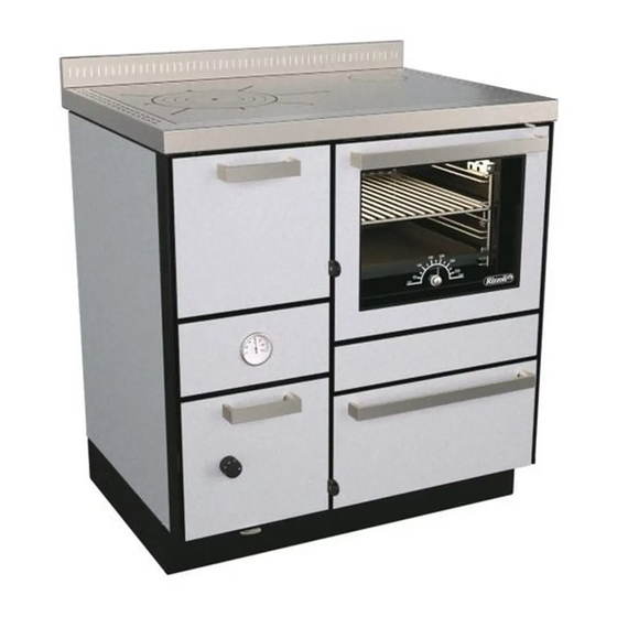
Col tempo la Rizzoli ha continuato ad affinare le proprie casa una cucina a legna. cucine utilizzando tecnologie sempre più moderne ed La Vostra scelta è... - Page 5 COMPONENTI DELLA TERMOCUCINA RTE 60 RTE 80/RTE 90 Figura 1 1 Alzatina 8 Porta cenere 15 Piastra Telaio...
- Page 6 13 Cruscotto 20 Termometro forno 7 Zoccolo 14 Porta forno ACCESSORI In dotazione alle termocucine a legna Rizzoli sono lazione, la manutenzione e l’uso quotidiano. presenti alcuni accessori che semplificano l’instal- • Cassetto cenere della termocucina, variabili in funzione del mo- • Guanto (serie RTVE) dello e della uscita fumi prescelta •...
-
Page 7: Installazione
INSTALLAZIONE AVVERTENZE Le termocucine a legna Rizzoli sono di facile in- disposizione del camino e la possibilità di effettua- stallazione; vanno comunque osservate alcune re gli allacciamenti necessari. Per lo spostamento precauzioni per evitare danneggiamenti dovuti a della termocucina evitate di trascinarla, spostatela imperizia. - Page 8 CAMINO Il camino è di vitale importanza per il corretto fun- garantito il corretto funzionamento della termocu- zionamento di una termocucina a legna. Le termo- cina. Per la costruzione del camino è obbligatorio cucine a legna sono studiate per garantire il mas- l’utilizzo di materiali adatti a resistere ad alta tem- simo rendimento, però...
- Page 9 Più è alto il cami- di corretta e di scorretta realizzazione del camino. no e maggiore è il tiraggio, se l’altezza del cami- RTE 60 RTE 80 - RTVE 80 Modello RTVE 60 RTE 90 - RTVE 90...
- Page 10 (so- e eventualmente effettuare le modifiche del caso pra, dietro, sul fianco). Prima di effettuare il colle- utilizzando i dispositivi forniti a corredo della ter- gamento della termocucina bisogna verificare che mocucina. RTE 60 - RTVE 60 Figura 7 – Termocucina multifumo senza forno, predisposizione dell’uscita fumi corretta. Si riporta l’esempio con uscita fumi a destra. L’uscita fumi a sinistra è simmetrica.
- Page 11 RTE 80 - RTE 90 - RTVE 80 - RTVE 90 Figura 8 – Termocucina multifumo con forno, predisposizione dell’uscita fumi corretta. Si riporta l’esempio con uscita fumi a destra. L’uscita fumi a sinistra è simmetrica. CORRETTO ALLACCIAMENTO AL CAMINO Se la canna fumaria parte dal piano inferiore ri- inserito e quindi girato in modo da restare bloc- spetto al punto di collegamento della termocucina cato.
- Page 12 USCITA FUMI POSTERIORE REGOLABILE (TERMOCUCINE CON FORNO) Tutti i modelli con forno presentano di serie la Su richiesta Rizzoli è in grado di fornire una lamie- possibilità di variare la posizione dell’uscita fumi ra aggiuntiva per poter utilizzare l’uscita fumi nelle posteriore. Lo spostamento si sviluppa sia oriz- posizioni intermedie.
- Page 13 LAMIERA STANDARD Modello standard RTE 80 - RTVE 80 RTE 90 - RTVE 90 Tabella 2a – Distanza minima e massima (in mm) del centro foro dell’uscita fumi. Non tiene in considerazione la tolleranza dovuta all’attacco a baionetta. Figura 12a – Vista posteriore della termocu- cina e rappresentazione dello spostamento minimo e massimo riguardo la posizione dell’uscita fumi posteriore con la lamiera standard. LAMIERA STANDARD CAPOVOLTA Modello standard RTE 80 - RTVE 80 RTE 90 - RTVE 90 Tabella 2b – Distanza minima e massima (in mm) del centro foro dell’uscita fumi. Non tiene in considerazione la tolleranza dovuta all’attacco a baionetta. Figura 12b – Vista posteriore della termocu- cina e rappresentazione dello spostamento minimo e massimo riguardo la posizione dell’uscita...
- Page 14 La presa d’aria del locale deve avere una superficie predisporre un condotto collegato direttamente minima di 80 cm2. con l’esterno dell’abitazione e effettuarne il col- Su richiesta Rizzoli può fornire delle valvole stu- legamento diretto con la presa d’aria della termo- Figura 13 – Installazione mediante presa d’aria nel locale e installazione con presa d’aria esterna collegata direttamente alla termocucina a legna.
- Page 15 Rizzoli. ATTENZIONE! Cappe aspiranti o ventilatori di estrazione di aria del locale potrebbero causare problemi per il corretto funzionamento dell’apparecchio in mancanza di apposita presa d’aria o in caso di presa d’aria sottodimensionata. ø Modelli RTE 60 - RTVE 60 RTE 80 - RTVE 80 RTE 90 - RTVE 90 Tabella 3 - Misure per collegamento presa aria esterna Misure in mm Ingresso aria esterna Figura 15 – Vista posteriore dello zoccolo della ter- mocucina e specifiche per il collegamen-...
- Page 16 2.12 COLLEGAMENTI ELETTRICI Il collegamento elettrico delle termocucine serve posta nel retro della termocucina. Devono essere unicamente per l’alimentazione della lampadina effettuati i corretti collegamenti di linea, neutro e del forno. L’allacciamento alla rete elettrica deve terra come indicato in figura 17. Il cavo e ogni altro essere effettuato da personale qualificato e se- dispositivo elettrico aggiunto deve essere dimen- condo le norme vigenti.
- Page 17 2.13 REGOLAZIONE DELLO ZOCCOLO Lo zoccolo delle termocucine è regolabile per adat- i piedini regolabili in altezza sia la regolazione del- tarsi nel modo migliore all’ambiente in cui la ter- la rientranza dello zoccolo rispetto al frontale. Per mocucina viene inserita. Per effettuare la regola- fare ciò...
- Page 18 2.14 PRIMA ACCENSIONE Prima dell’uso è necessario togliere i materiali di presente acqua nella caldaia. Si consiglia di effet- imballaggio presenti nel forno e nella cassa porta tuare subito una prima accensione della termocu- legna, togliere le etichette adesive, togliere la pelli- cina come verifica della corretta installazione.
-
Page 19: Impianto Di Riscaldamento
IMPIANTO DI RISCALDAMENTO GENERALITÀ Le termocucine serie RTE - RTVE sono dotate di la normativa UNI 10683. Le termocucine sono do- caldaia per sfruttare il calore prodotto dall’appa- tate di tutte le predisposizioni necessarie per una recchio mediante un impianto con fluido vettore corretta installazione, ogni componente esterno per riscaldamento e produzione di acqua calda. - Page 20 ATTACCHI LATERALI Su tutti i modelli di termocucine serie RTE - RTVE l’installazione sono presenti due attacchi di anda- è possibile avere, su richiesta all’atto dell’ordine, gli ta (per circuito acqua calda e per riscaldamento) e attacchi relativi all’impianto di riscaldamento sul...
- Page 21 Le termocuci- a vaso chiuso realizzando il sistema di scarico ter- ne serie RTE - RTVE sono dotate di serie di tutte le mico e quindi collegando i relativi connettori come predisposizioni per realizzare lo scarico termico. Le descritto più...
- Page 22 Su richiesta Rizzoli to deve essere inserita nell’apposito bulbo di colle- può fornire una valvola di scarico termico adatta gamento.
- Page 23 Figura 24 –Esempio di impianto con termocucina come generatore di calore.
- Page 24 Figura 25 –Esempio di impianto con termocucina come generatore di calore.
- Page 25 Figura 26 –Esempio di impianto con termocucina come generatore di calore.
- Page 26 Figura 27 –Esempio di impianto con termocucina con doppi attacchi (serie RTE - RTVE con attacchi laterali) come generatore di calore.
-
Page 27: Uso
FUNZIONAMENTO DELLA TERMOCUCINA Durante il funzionamento, all’interno della termo- stione avvenga in più punti diversi per ottenere la cucina avviene una reazione di combustione tra massima efficienza. In particolare è presente una il combustibile (la legna inserita nella camera di alimentazione di aria primaria, che affluisce nella combustione) e il comburente (l’ossigeno presente parte inferiore della camera di combustione attra-... - Page 28 questo modo si ottiene un miglioramento del tirag- vigore si deve richiudere la chiave in modo da for- gio. Per accendere il fuoco potete utilizzare come zare il fumo a riscaldare tutte le parti della termo- combustibile legna ben secca, spaccata molto sot- cucina.
- Page 29 Figura 29 – Regolazione della leva della presa d’aria. Figura 30 – Regolazione dell’aria primaria. Il regolato- La valvola è aperta in corrispondenza re si apre ruotando la manopola in senso della posizione indicata con la lettera “A”, orario. mentre è chiusa nella posizione indicata con la lettera “B”. ATTENZIONE! Per le termocucine RTVE, nel caricare la legna si raccomanda di mantene- re una distanza di alcuni centimetri tra il vetro interno della porta fuoco e il combustibile, in modo da non esporre il vetro a temperature eccessive che lo potrebbero danneggiare. REGOLAZIONE DELLA GRIGLIA Le termocucine sono dotate di griglia regolabile in altezza che permette di variare le dimensioni della camera di combustione a seconda delle esigenze dell’utilizzatore. La posizione più alta permette di avere la fiamma a diretto contatto con la piastra, è...
- Page 30 COTTURA SULLA PIASTRA La piastra radiante in acciaio è espressamente stu- cibi caldi. Per ottenere la massima velocità nella diata per permettere di cucinare in modo sempli- cottura occorre utilizzare legna spaccata sottile ed ce e rapido. La parte più calda della piastra è in effettuare le regolazioni come descritto sopra.
- Page 31 ILLUMINAZIONE DEL FORNO (TERMOCUCINE CON FORNO) Nelle termocucine con forno è presente un im- pianto di illuminazione del forno stesso che, insie- me all’ampio vetro della porta, permette di control- lare a vista il procedimento della cottura nel forno senza dover aprire la porta. L’interruttore di accen- sione si trova estraendo la cassa porta legna su uno dei montanti laterali.
- Page 32 4.10 PORTA ACCESSORI (TERMOCUCINE CON FORNO) All’interno della cassa porta legna è presente un piccolo cassetto porta accessori che può esse- re molto utile per tenere in ordine gli oggetti più piccoli, che in questo modo restano separati dalla legna. Figura 35 – Porta accessori montato sulla cassa porta legna 4.11 PORTATEGLIA (TERMOCUCINE CON FORNO) In dotazione alla termocucina è...
- Page 33 4.13 PROTEZIONE PORTA FUOCO (OPTIONAL) Sulle termocucine serie RTVE è possibile mettere su richiesta una protezione in acciaio da posiziona- re sulla porta fuoco. Questa protezione è stata stu- diata per schermare la porta quando le operazioni di preparazione dei cibi richiedono la presenza costante dell’utilizzatore davanti alla termocucina oppure in presenza di bambini.
-
Page 34: Manutenzione
Su richiesta Rizzoli fornisce degli specifici specifici per la pulizia dell’acciaio inox. Evitate di prodotti per la pulizia dell’acciaio inox. Per le par- utilizzare detersivi in polvere. - Page 35 All’interno della camera di combustione della ter- cerchiata. mocucina a legna sono posizionate delle lamiere Successivamente è necessario togliere la piastra in mobili in acciaio che svolgono una duplice fun- modo da poter avere maggior spazio per eseguire zione: consentono l’entrata dell’aria secondaria di l’operazione.
- Page 36 CASSETTO CENERE Tutte le volte che si utilizza la termocucina occorre to rendendo poi più laboriosa la pulizia. In caso di controllare il cassetto della cenere che si trova sot- accumulo eccessivo della cenere il fuoco potrebbe to la camera di combustione. Quando il cassetto è non essere alimentato in modo corretto e quindi pieno occorre svuotarlo.
- Page 37 ATTENZIONE! Se la pulizia del camino non viene fatta come raccomandato ci può essere il pericolo di incendio della canna fumaria. PULIZIA DEI VETRI I vetri della porta del forno e, nei modelli serie bustione è stata studiata in modo da pulirsi da sola RTVE, della porta della camera di combustione si durante l’uso della termocucina. Ciò nonostante possono pulire con i normali prodotti specifici esi- di quando in quando potrebbe essere necessaria stenti in commercio.
- Page 38 lampada, sfilare e rimuovere la lampadina, inserire forno. Per fare questo dovete svitare il coprilam- la nuova lampadina e infine riavvitare il coprilam- pada, rimuovere i depositi esterni dovuti ai fumi di pada. Di tanto in tanto è necessario effettuare la cottura, lavare il coprilampada e dopo averlo ben pulizia del vetro coprilampada della lampadina del asciugato riavvitarlo nella propria sede.
-
Page 39: Cosa Fare Se
COSA FARE SE... Problemi Effetti Possibili rimedi • Verificare che tutte le regolazioni dell’aria siano nella loro posizione di massima apertura • Ve- rificare che cenere e residui non ostruiscano la griglia • Verificare che la griglia non sia montata alla rovescia (la parte piana va rivolta verso l’al- to) •... -
Page 40: Dati Tecnici
Ruggine sulla piastra cottura. come prescritto • Contattare il proprio rivendi- tore o il servizio clienti DATI TECNICI DATI TECNICI RTE 60 RTE 80 RTE 90 Modello RTVE 60 RTVE 80 RTVE 90 Peso... - Page 41 RTE 60 b.e. RTE 80 b.e. RTE 90 b.e. Modello RTVE 60 b.e. RTVE 80 b.e. RTVE 90 b.e. Peso 193 kg 235 kg 260 kg Potenza nominale 5,7-11,1 kW 11,3 kW 11,3 kW Potenza nominale resa all’acqua 2,6-5,7 kW 6,5 kW 6,5 kW Potenza nominale resa all’ambiente...
- Page 42 Distanze di sicurezza da materiale infiammabile o sensibile al calore in assenza di sistemi di isolamento aggiuntivi. Modello Lateralmente Dietro Davanti Sopra RTE 60 - RTVE 60 25 cm 25 cm 80 cm 60 cm RTE 80 - RTVE 80 35 cm...
- Page 43 REGOLAZIONI ALLA POTENZA NOMINALE Leva presa Regolatore Chiave Modello d’aria di tiraggio di avviamento RTE 60 - RTVE 60 Aperta Aperta Chiusa RTE 80 - RTVE 80 Aperta Aperta Chiusa RTE 90 - RTVE 90 Aperta Aperta Chiusa RTE 60 b.e. - RTVE 60 b.e. Aperta a metà...
- Page 44 La ditta Rizzoli, a proprio insindacabile giudizio mesi. Per le riparazioni presso i Centri di Assisten- deciderà se la prestazione di garanzia debba essere za della ditta Rizzoli il cliente è tenuto a versare le fatta in loco oppure presso i propri stabilimenti. spese di trasporto.
- Page 45 TRIBUNALE COMPETENTE Per qualsiasi controversia o contestazione sarà com- petente sempre e solo il foro di Bolzano. Avvertenza Rizzoli S.r.l. è costantemente impegnata nel migliorare i propri prodotti, per questo il contenuto del presente libretto di istruzioni può cambiare senza preavviso.
- Page 46 Ai sensi dei regolamenti prodotti da costruzione n. 305/2011 N.85 Codice di identificazione unico del Prodotto-tipo RTVE 60 Modello e/o n. serie (art. 11-4) RTE 60 - RTVE 60 Usi previsti del prodotto conformemente Riscaldamento e cottura alla relativa specifica tecnica armonizzata uso domestico Nome o marchio registrato del fabbricante (art. 11-5) Rizzoli s.r.l.
- Page 47 Ai sensi dei regolamenti prodotti da costruzione n. 305/2011 N.87 Codice di identificazione unico del Prodotto-tipo RTVE 60 A Modello e/o n. serie (art. 11-4) RTE 60 A - RTVE 60 A Usi previsti del prodotto conformemente Riscaldamento e cottura alla relativa specifica tecnica armonizzata uso domestico Nome o marchio registrato del fabbricante (art. 11-5) Rizzoli s.r.l.
- Page 48 Ai sensi dei regolamenti prodotti da costruzione n. 305/2011 N.89 Codice di identificazione unico del Prodotto-tipo RTVE 60 B Modello e/o n. serie (art. 11-4) RTE 60 B - RTVE 60 B Usi previsti del prodotto conformemente Riscaldamento e cottura alla relativa specifica tecnica armonizzata uso domestico Nome o marchio registrato del fabbricante (art. 11-5) Rizzoli s.r.l.
- Page 49 Ai sensi dei regolamenti prodotti da costruzione n. 305/2011 N.100 Codice di identificazione unico del Prodotto-tipo RT 90 Modello e/o n. serie (art. 11-4) RTE 80 - RTE 90 RTVE 80 - RTVE 90 Usi previsti del prodotto conformemente Riscaldamento e cottura alla relativa specifica tecnica armonizzata uso domestico Nome o marchio registrato del fabbricante (art.
- Page 50 N.101 Codice di identificazione unico del Prodotto-tipo ST 90 Modello e/o n. serie (art. 11-4) RTE 80 B - RTE 90 B RTVE 80 B - RTVE 90 B Usi previsti del prodotto conformemente Riscaldamento e cottura alla relativa specifica tecnica armonizzata uso domestico Nome o marchio registrato del fabbricante (art.
- Page 51 INDICE DISPOSIZIONI pag. Disposizioni generali pag. Disposizioni di sicurezza pag. Combustibile raccomandato pag. Altri combustibili pag. Componenti della termocucina pag. Accessori pag. INSTALLAZIONE pag. Avvertenze pag. Distanze di sicurezza pag. Camino pag. Dimensioni e forme corrette del camino pag. Canna fumaria pag.
- Page 52 INDICE Valvola per l’eccesso di vapore (termocucine con forno) pag. Illuminazione del forno (termocucine con forno) pag. Teglia con guide scorrevoli (termocucine con forno) pag. 4.10 Porta accessori (termocucine con forno) pag. 4.11 Portateglia (termocucine con forno) pag. 4.12 Cassa porta legna (termocucine con forno) pag.
- Page 53 INDICE Dichiarazione di prestazione n. 85 pag. Dichiarazione di prestazione n. 87 pag. Dichiarazione di prestazione n. 89 pag. Dichiarazione di prestazione n. 100 pag. Dichiarazione di prestazione n. 101 pag.
-
Page 54: Anweisungen
Brennstoffe, die behagliche Wärme des natürlichen Feu- lung von Holzherden im typischen Stil der Dolomitentäler ers und der angenehme Duft des aus unseren Wäldern begann. Mit der Zeit hat Rizzoli seine Produkte durch den stammenden Holzes sind Argumente, die den Einsatz Einsatz modernster und zukunftsorientierter Technologi- eines Holzherdes nicht nur interessant, sondern aus en ständig verbessert, ohne jedoch die Eleganz, Schönheit... -
Page 55: Empfohlener Brennstoff
Holz, Papier, Karton, Küchenab- schließlich die empfohlenen Brennstoffe. Auch flüs- fälle und generell jedes nicht vorgesehene Material sige Brennstoffe dürfen nicht verwendet werden. HERDBESTANDTEILE RTE 60 RTE 80/RTE 90 Abb. 1 1 Wischleiste 8 Aschekastentür 15 Herdplatte 2 Herdrahmen... -
Page 56: Zubehör
6 Flammenschutz 13 Reinigungsöffnung 20 Thermometer Backofen 7 Sockel 14 Backofentür ZUBEHÖR Im Lieferumfang der Rizzoli-Zentralheizungsherde tage, Wartung und den täglichen Gebrauch des sind einige Zubehörteile enthalten, die die Mon- Herdes erleichtern. • Aschekasten • Backofenrost (Modelle mit Backofen) • Schutzhandschuh (Serie RTVE) •... -
Page 57: Montage
Mindestabstand zur Lösung eventueller Probleme werden auf An- von 60 cm zur Herdplatte eingehalten werden. frage von Rizzoli geliefert. Falls der Herd zwischen Falls über dem Herd eine Dunstabzugshaube an- nicht wärmeempfindlichen Materialien eingebaut gebracht werden soll, muss diese speziell für den wird, ist ein Mindestsicherheitsabstand von 1-2 Einsatz bei hohen Temperaturen geeignet sein. -
Page 58: Rauchabzug
Der Rauchabzug ist von lebenswichtiger Bedeu- ordnungsgemäße Betrieb des Zentralheizungs- tung für den einwandfreien Betrieb eines Zent- herdes nicht garantiert werden. Für den Bau des ralheizungsherdes. Rizzoli-Zentralheizungsherde Rauchabzugs sind hochtemperaturbeständige sind auf höchste Leistung ausgelegt, wobei diese Baumaterialien, die den Brandschutzvorschriften jedoch stark vom Verhalten des Rauchabzugs be- entsprechen, vorgeschrieben. -
Page 59: Rauchabzugrohr
Rauchabzug für das aus- beschränken. Abb. 5 zeigt einige Beispiele für die gewählte Herdmodell garantiert wird. Je höher der richtige und falsche Ausführung des Rauchabzugs. RTE 60 RTE 80 - RTVE 80 Modell RTVE 60 RTE 90 - RTVE 90 ø Rauchausgang... -
Page 60: Anschluss- Oder Rauchrohrstutzen
Anschlussöffnungen gut verschlossen sind. zungsherden an mehreren Positionen befinden Eventuelle Änderungen können mit den mitgelie- (oben, hinten, seitlich). Vor dem Anschluss des ferten Zubehörteilen vorgenommen werden. Herdes ist sicherzustellen, dass alle nicht benutz- RTE 60 - RTVE 60 Abb. 7 - Mehrfachanschluss - Zentralheizungsherd ohne Backofen - korrekte Vorbereitung für den Anschluss. Beispiel mit Rauchausgang rechts. Der Rauchausgang auf der linken Seite ist symmetrisch. -
Page 61: Richtiger Anschluss An Den Rauchabzug
RTE 80 - RTE 90 - RTVE 80 - RTVE 90 Abb. 8 - Mehrfachanschluss - Zentralheizungsherd mit Backofen - korrekte Vorbereitung für den Anschluss. Beispiel mit Rauchausgang rechts. Der Rauchausgang auf der linken Seite ist symmetrisch. RICHTIGER ANSCHLUSS AN DEN RAUCHABZUG Falls das Rauchabzugsrohr unter der Anschluss- schluss verwendet werden. Um den Anschluss- stelle des Zentralheizungsherdes beginnt, kann stutzen in der richtigen Position zu fixieren, wird es erforderlich sein, ihn unterhalb des Rauchrohr- er eingeführt und bis zum Anschlag gedreht. -
Page 62: Regulierbarer Rauchausgang Auf Der Rückseite (Herde Mit Backofen)
2.10 REGULIERBARER RAUCHAUSGANG AUF DER RÜCKSEITE (ZENTRALHEIZUNGSHERDE MIT BACKOFEN) Bei allen Modellen mit Backofen ist es serienmäßig ge kann Rizzoli eine zusätzliche Anschlussplatte möglich, die Position des Rauchausgangs auf der mit Rauchausgang in den mittleren Positionen Rückseite zu verändern. Dieser kann horizontal liefern. Für die horizontale und vertikale Regulie- und vertikal verstellt werden, um sich bestmög-... - Page 63 STANDARD-ANSCHLUSSPLATTE Modelle standard RTE 80 - RTVE 80 RTE 90 - RTVE 90 Tabelle 2a - Mindest- und Maximalabstand (in mm) ab Rauchausgangs-Mitte ohne Berücksichtigung der Toleranz des Anschlussstutzens mit Bajonettver- schluss. Abb. 12a - Rückansicht des Zentralhei- zungsherdes und Darstellung der min. und max. Verschiebung des Rauchausgangs auf der Rückseite mit der Standard-Anschlussplatte. UMGEDREHTE STANDARD-ANSCHLUSSPLATTE Modelle standard RTE 80 - RTVE 80 RTE 90 - RTVE 90 Tabelle 2b - Mindest- und Maximalabstand (in mm) ab Rauchausgangs-Mitte ohne Berücksichtigung der Toleranz des Anschlussstutzens mit Bajonettver- schluss. Abb. 12b - Rückansicht des Zentralhei- zungsherdes und Darstellung der min. und max. Verschiebung des...
-
Page 64: Frischluftzufuhr
ZUSÄTZLICHE ANSCHLUSSPLATTE (OPTIONAL) Modelle RTE 80 - RTVE 80 RTE 90 - RTVE 90 Tabelle 2c – Mindest- und Maximalabstand (in mm) ab Rauchausgangs-Mitte mit der zusätzlichen Anschlussplatte ohne Berücksichtung der Toleranz des Anschlussstutzens mit Bajonettverschluss. Eventuell kann es notwendig sein, die zusätzliche Anschluss- platte zu drehen, um die gewünschte Position zu erhalten. Abb. 12c - Rückansicht des Zentralhei- zungsherdes und Darstellung der min. und max. Verschiebung des Rauchausgangs auf der Rückseite mit der zusätzlichen Anschluss- platte. 2.11... - Page 65 Um den Anschluss zu erleichtern, empfiehlt es Abb. 15), vorzunehmen. Weitere Anschlusslösun- sich, die externe Frischluftzufuhr entweder über gen sind nach vorheriger Absprache mit Rizzoli den Boden oder an der Rückwand des Herdes, in möglich. Sockelhöhe, je nach Modell (siehe Tabelle 3 und ACHTUNG! Dunstabzugshauben oder Lüftungsanlagen im Aufstellungsraum können...
-
Page 66: Elektrische Anschlüsse
2.12 ELEKTRISCHE ANSCHLÜSSE Der elektrische Anschluss von Zentralheizungsher- Klemmbrett auf der Herdrückseite angeschlossen den dient ausschließlich zur Stromversorgung der werden. Alle Anschlüsse an die Stromversorgung Backofenlampe. Der Anschluss an die Stromver- (Phase, Neutralleiter und Schutzleiter) müssen wie sorgung muss von einem qualifizierten Fachmann in der Abbildung 17 ersichtlich, korrekt ausgeführt gemäß... -
Page 67: Einstellung Des Sockels
2.13 EINSTELLUNG DES SOCKELS Der Sockel der Zentralheizungsherde ist regulier- derseite als auch die Herdhöhe durch die Schraub- bar, damit er bestmöglich dem Aufstellungsraum füße eingestellt werden. Hierzu muss jeder einzel- angepasst werden kann. Die Einstellung des So- ne Schraubfuß in den Ecken des Sockels reguliert ckels erfolgt im inneren Unterteil des Herdes. -
Page 68: Erste Inbetriebnahme
2.14 ERSTE INBETRIEBNAHME Vor der ersten Inbetriebnahme des Herdes muss geschlossen werden und im Heizkessel muss sich jegliches Verpackungsmaterial aus dem Backofen Wasser befinden. Es wird empfohlen, den Herd und der Holzlade, eventuelle Klebeetiketten sowie sofort ein erstes Mal in Betrieb zu nehmen, damit die zum Schutz der Herdplatte verwendete Plas- seine ordnungsgemäße Installation kontrolliert tikfolie entfernt werden. -
Page 69: Heizungsanlage
1) Anschluss Thermostatfühler (Optional) Ø ½“ Innengewinde 2) Zulaufanschluss Ø 1“¼ Innengewinde 3) Muffe für Fühler Sicherheitswärmetauscher (Optional) Ø ½“ Innengewinde 4) Anschlüsse für Kreislauf Sicherheitswärme- tauscher (Optional) Ø ½“ Außengewinde 5) Rücklaufanschluss Ø 1“¼ Innengewinde 6) Ablaufanschluss Ø ½“ Innengewinde Abb. 20 - Anschlussschema der Modelle RTE 60 und RTVE 60 mit Rauchausgang rechts (Rückansicht). Bei Modellen mit Rauchausgang links befinden sich die Anschlüsse symmetrisch. -
Page 70: Seitliche Anschlüsse
800/900 Abb. 21 - Anschlussschema der Modelle RTE 80, RTVE 80, RTE 90 und RTVE 90 mit Rauchausgang rechts (Rückansicht). Bei Modellen mit Rauchausgang links befinden sich die Anschlüsse symmetrisch. Vor der Inbetriebnahme des Zentralheizungs- auf der Rückseite der Zentralheizungsherde RTE - herdes muss dieser an die Heizungsanlage ange- RTVE, zwischen den Anschlüssen und der Wand schlossen werden. Bei Gebrauch des Zentralhei- des Aufstellungsraums, beträgt ca. 35 mm. Dieser zungsherdes mit leerem Heizkessel oder ohne An- reicht normalerweise nicht für die hydraulischen... -
Page 71: Installationsmöglichkeiten
Rücklaufanschluss auch für die Verbindung mit Ausdehnungsgefäß vor. Voraussetzung hierzu ist dem Zuflussrohr verwendet werden. Zentralhei- jedoch ihre Ausstattung mit einem Kreislauf für zungsherde RTE - RTVE können mit Anlagen mit einen Sicherheitswärmetauscher im Inneren des geschlossenen Ausdehnungsgefäß installiert wer- Heizkessels. Die Zentralheizungsherde der Serie den, wenn ein Kreislauf für den Sicherheitswärme-... -
Page 72: Sicherheit
Anlage müssen von Drittlieferanten die Warmbrauchwasseraufbereitung verwendet nach Angaben des Planers oder Installateurs der werden. Bei Bedarf kann Rizzoli ein passendes Anlage erworben werden. Zur Ausführung dieser thermisches Ablaufventil für Ihr Gerät liefern. Hilfsanlage müssen die austauschbaren Zu- und Fühler... - Page 73 Abb. 24 –Beispiel einer Heizungsanlage mit Zentralheizungsherd als Wärmeerzeuger.
- Page 74 Abb. 25 –Beispiel einer Heizungsanlage mit Zentralheizungsherd als Wärmeerzeuger.
- Page 75 Abb. 26 –Beispiel einer Heizungsanlage mit Zentralheizungsherd als Wärmeerzeuger.
- Page 76 Abb. 27 - Beispiel einer Heizungsanlage mit Zentralheizungsherd mit doppelten Anschlüssen (Serie RTV-RTVE mit seitlichen Anschlüssen) als Wärmeerzeuger.
-
Page 77: Gebrauch
GEBRAUCH BETRIEB DES ZENTRALHEIZUNGSHERDES Während des Betriebs erfolgt im Herd ein Ver- um ein Maximum an Effizienz zu erreichen. Zu brennungsprozess zwischen dem Brennstoff (im diesem Zweck wird sowohl Primärluft, die in den Feuerraum geladenes Holz) und dem Sauerstoff- unteren Teil des Feuerraums durch den mit Holz träger (in der Luft des Aufstellungsraums enthal- belegten Feuerrost strömt, wie auch an einer oder tener Sauerstoff). -
Page 78: Luftregulierung
mer und Rauchabzug hergestellt, wodurch der Zug er lebhaft brennt, muss man die Anheizklappe des Zentralheizungsherdes verbessert wird. Ver- schließen, damit sich die Wärme auf alle Teile des wenden Sie als Brennstoff gut getrocknetes, sehr Herdes verteilt. Der Herd ist für den Betrieb mit dünnes Scheitholz zusammen mit den im Handel geschlossener Anheizklappe ausgelegt. -
Page 79: Höhenverstellbarer Feuerrost
Abb. 29 - Einstellung der Frischluftzufuhr-Regulie- Abb. 30 - Einstellung der Primärluft. Durch das rung. Wenn sich der Hebel auf der Position Drehen im Uhrzeigersinn, öffnet sich die “A“ befindet, ist die Luftzufuhr offen. Regulierung. Auf der Position “B“ ist die Luftzufuhr geschlossen. ACHTUNG! Achten Sie darauf, dass beim Holz einlegen bei den Modellen RTVE ein Ab- stand von einigen cm zwischen Innenscheibe der Feuerraumtür und Brennstoff bleibt, um das Glas nicht zu hohen Temperaturen auszusetzen, die es beschädigen könnten. HÖHENVERSTELLBARER FEUERROST Zentralheizungsherde sind mit einem höhenver- stellbarem Feuerrost ausgestattet, mit dem man... -
Page 80: Kochen Auf Der Herdplatte
KOCHEN AUF DER HERDPLATTE Die Stahl-Herdplatte ist eigens für schnelles und empfiehlt sich die Verwendung von klein gespal- einfaches Kochen gedacht. Die heißeste Stelle der tenem Holz und die Befolgung der oben ange- Herdplatte ist im Bereich der runden Einlegeplat- führten Einstellungen. - Page 81 BACKOFENBELEUCHTUNG (ZENTRALHEIZUNGSHERDE MIT BACKOFEN) Zentralheizungsherde mit Backofen sind mit einer elektrischen Innenbeleuchtung und großem Back- ofen-Sichtfenster zur bequemen Kontrolle des Back- und Bratvorganges ausgestattet, ohne dass hierzu die Backofentür geöffnet werden muss. Der Lichtschalter befindet sich seitlich der Holzlade. Um ihn zu betätigen muss die Holzlade herausge- zogen werden.
- Page 82 4.10 ZUBEHÖRFACH (ZENTRALHEIZUNGSHERDE MIT BACKOFEN) Im Inneren der Holzlade befindet sich ein kleines Zubehörfach welches als praktische Ablage für kleine Teile, um diese getrennt vom Brennholz auf- zubewahren, dient. Abb. 35 - Im Inneren der Holzlade montiertes Zu- behörfach. 4.11 BACKBLECHHALTER (ZENTRALHEIZUNGSHERDE MIT BACKOFEN) Im Lieferumfang des Zentralheizungsherdes steht Backofen genommen werden kann. Der Halter ein Backblechhalter zur Verfügung, anhand dessen wird einfach am Rand des Backblechs angebracht - ohne Einsatz von Topflappen oder Tüchern, das...
- Page 83 ACHTUNG! Bewahren Sie keine leicht entflammbaren Produkte in der Holzlade auf! Die gelagerten Gegenstände dürfen keinesfalls bis an den oberen Rand der Holzlade reichen. 4.13 SCHUTZ DER FEUERRAUMTÜR (OPTIONAL) Auf Anfrage ist für die Modelle RTVE ein Edel- stahlschutz für die Feuerraumtür erhältlich, der bei längerem Aufenthalt vor dem Herd oder in Anwesenheit von Kindern zum Abschirmen der Feuerraumtür verwendet wird.
-
Page 84: Wartung
Reinigungsmitteln oder- bei hartnäckigen Reinigung alles wieder wie neu. Auf Anfrage liefert Verschmutzungen - mit speziellen im Handel er- Rizzoli spezielle Edelstahlreiniger. Zur Reinigung von hältlichen Edelstahlreinigern gereinigt. Verwenden emaillierten oder lackierten Teile niemals Schleifmit- Sie aber nicht Reinigungspulver. Verwenden Sie tel, scheuernde, aggressive oder säurehaltige Reini-... - Page 85 Im Inneren der Brennkammer des Zentralheizungs- herausgenommen werden, dann entfernt man die herdes befinden sich mobile Stahlplatten, die eine Herdplatte, damit man mehr Platz hat, diesen Vorgang Doppelfunktion erfüllen: sie dienen zum Schutz zwi- durchzuführen. Nun können zuerst die Metallplatten schen Feuer und Heizkessel und sie ermöglichen auf von den Seitenwänden und als Letztes die hinteren einer optimalen Höhe den Einlass der Sekundärluft,...
- Page 86 ASCHEKASTEN Vor jedem Gebrauch des Zentralheizungsherdes und sich damit die Reinigung aufwendiger gestal- muss der Aschekasten unter dem Feuerraum kon- ten könnte. Durch eine zu große Aschenansamm- trolliert werden. Falls er voll ist, muss er entleert lung könnte das Feuer nicht richtig gespeist wer- werden, da Asche aus dem Kasten herausfallen den und die Verbrennung wäre unregelmäßig.
- Page 87 ACHTUNG! Bei unzureichender Rauchabzugreinigung besteht die Gefahr eines Schorn- steinbrandes REINIGUNG DER SICHTFENSTER Zur Reinigung der Sichtfenster der Backofen- und nigen sich während des Betriebes von selbst. Hin der Feuerraumtür der Modelle RTVE verwenden und wieder kann jedoch auch eine manuelle Rei- Sie die spezifischen, handelsüblichen Reinigungs- nigung der Scheibe, die direkten Kontakt mit dem mittel.
- Page 88 „10 grüne Regeln“ angeführte Seriennum- sind schneller und preiswerter, wenn der entspre- mer des Herdes an. Diese finden Sie auch seitlich chende Herdbauteil direkt oder über einen Wie- der Holzlade auf dem Typenschild. derverkäufer an die Firma Rizzoli retourniert wird.
-
Page 89: Was Tun, Wenn
WAS TUN, WENN... Probleme Anzeichen Mögliche Lösungen • Kontrollieren, ob alle Luftregulierungen auf der höchsten Öffnungsstufe eingestellt sind • Kontrollieren, ob keine Asche und Verbren- nungsrückstände den Feuerrost verstopfen • Kontrollieren, ob der Feuerrost korrekt einge- legt wurde (der flache Teil gehört nach oben) •... -
Page 90: Technische Daten
Roststellen und Verformungen auf ben regelmäßig reinigen und pflegen • Den zu- Rostflecken der Herdplatte. ständigen Wiederverkäufer oder Kundendienst verständigen. TECHNISCHE DATEN TECHNISCHE DATEN RTE 60 RTE 80 RTE 90 Modell RTVE 60 RTVE 80 RTVE 90 Gewicht 193 kg... - Page 91 RTE 60 r.L. RTE 80 r.L. RTE 90 r.L. Modell RTVE 60 r.L. RTVE 80 r.L. RTVE 90 r.L. Gewicht 193 kg 235 kg 260 kg Nennwärmeleistung 5,7-11,1 kW 11,3 kW 11,3 kW Leistung wasserseitig 2,6-5,7 kW 6,5 kW 6,5 kW Raumheizvermögen...
- Page 92 SICHERHEITSABSTÄNDE Sicherheitsabstände zu leicht entflammbaren oder temperaturempfindlichen Materialien ohne zusätzli- che Isoliersysteme. Modell Seitlich Hinten Vorne Oben RTE 60 - RTVE 60 25 cm 25 cm 80 cm 60 cm RTE 80 - RTVE 80 35 cm 35 cm 80 cm...
- Page 93 EINSTELLUNGEN NENNWÄRMELEISTUNG Frischluftzufuhr- Zugregler Anheizklappe Modell Regulierung RTE 60 - RTVE 60 Offen Offen Geschlossen RTE 80 - RTVE 80 Offen Offen Geschlossen RTE 90 - RTVE 90 Offen Offen Geschlossen RTE 60 r.L. - RTVE 60 r.L. Halboffen Leicht geöffnet Geschlossen RTE 80 r.L. - RTVE 80 r.L. Halboffen Leicht geöffnet Geschlossen RTE 90 r.L. - RTVE 90 r.L.
-
Page 94: Garantie
GARANTIE ERKLÄRUNG ZUR FACHGERECHTEN KONSTRUKTION Die Firma Rizzoli garantiert, dass das Gerät alle in- ler ist. Das Gerät ist das Ergebnis jahrzehntelanger ternen Kontrollen und Abnahmen bestanden hat, Erfahrung der Firma Rizzoli, die hiermit dessen dass es in einem einwandfrei funktionierendem fachgerechte Konstruktion und Ausführung ga-... - Page 95 Firma Rizzoli gen Gerichtsstand auszuwählen. das Recht vor, auch einen anderen Gerichtsstand Hinweis Die Firma Rizzoli GmbH ist stets um die Verbesserung seiner Erzeugnisse bemüht und behält sich deshalb das Recht vor, eventuelle Änderungen dieser Gebrauchsanweisung ohne Vorankündigung vorzunehmen.
- Page 96 LEISTUNGSERKLÄRUNG Gemäß der Bauproduktverordnung Nr. 305/2011 N.85 Eindeutiger Identifikationscode des Produkttyps RTVE 60 Modell und/oder Seriennr. (Art. 11-4) RTE 60 - RTVE 60 Vorgesehene Verwendung des Produkts Kochen von Speisen in Übereinstimmung mit der geltenden, Raumheizer harmonisierten technischen Spezifikation Name oder registriertes Warenzeichen Rizzoli GmbH des Herstellers (Art.
- Page 97 LEISTUNGSERKLÄRUNG Gemäß der Bauproduktverordnung Nr. 305/2011 N.87 Eindeutiger Identifikationscode des Produkttyps RTVE 60 A Modell und/oder Seriennr. (Art. 11-4) RTE 60 A - RTVE 60 A Vorgesehene Verwendung des Produkts Kochen von Speisen in Übereinstimmung mit der geltenden, Raumheizer harmonisierten technischen Spezifikation Name oder registriertes Warenzeichen Rizzoli GmbH des Herstellers (Art.
- Page 98 LEISTUNGSERKLÄRUNG Gemäß der Bauproduktverordnung Nr. 305/2011 N.89 Eindeutiger Identifikationscode des Produkttyps RTVE 60 B Modell und/oder Seriennr. (Art. 11-4) RTE 60 B - RTVE 60 B Vorgesehene Verwendung des Produkts Kochen von Speisen in Übereinstimmung mit der geltenden, Raumheizer harmonisierten technischen Spezifikation Name oder registriertes Warenzeichen Rizzoli GmbH des Herstellers (Art.
- Page 99 Gemäß der Bauproduktverordnung Nr. 305/2011 N.100 Eindeutiger Identifikationscode des Produkttyps RT 90 Modell und/oder Seriennr. (Art. 11-4) RTE 80 - RTE 90 - RTVE 80 - RTVE 90 Vorgesehene Verwendung des Produkts Kochen von Speisen in Übereinstimmung mit der geltenden, Raumheizer harmonisierten technischen Spezifikation...
- Page 100 Gemäß der Bauproduktverordnung Nr. 305/2011 N.101 Eindeutiger Identifikationscode des Produkttyps ST 90 Modell und/oder Seriennr. (Art. 11-4) RTE 80 B - RTE 90 B RTVE 80 B - RTVE 90 B Vorgesehene Verwendung des Produkts Kochen von Speisen in Übereinstimmung mit der geltenden, Raumheizer...
- Page 101 INHALTSVERZEICHNIS ANWEISUNGEN Allgemeine Anweisungen Sicherheitshinweise Empfohlener Brennstoff Andere Brennstoffe Herdbestandteile Zubehör MONTAGE Anweisungen Sicherheitsabstände Rauchabzug Richtige Abmessungen und Formen des Rauchabzugs Rauchabzugrohr Schornsteinaufsatz Anschluss- oder Rauchrohrstutzen Rauchausgänge Richtiger Anschluss an den Rauchabzug 2.10 Regulierbarer Rauchausgang auf der Rückseite (Herde mit Backofen) 2.11 Frischluftzufuhr 2.12...
- Page 102 INHALTSVERZEICHNIS Dampfableitungsventil (Zentralheizungsherde mit Backofen) Backofenbeleuchtung (Zentralheizungsherde mit Backofen) Backblech auf Teleskopschienen (Zentralheizungsherde mit Backofen) 4.10 Zubehörfach (Zentralheizungsherde mit Backofen) 4.11 Backblechhalter (Zentralheizungsherde mit Backofen) 4.12 Holzlade (Zentralheizungsherde mit Backofen) 4.13 Schutz der Feuerraumtür (optional) 4.14 Herdplattenabdeckung (optional) WARTUNG Reinigung Reinigung der sichtbaren Teile Wartung der Metallplatten in der Brennkammer Reinigung des Feuerrostes...
- Page 103 INHALTSVERZEICHNIS Leistungserklärung Nr. 85 Leistungserklärung Nr. 87 Leistungserklärung Nr. 89 Leistungserklärung Nr. 100 Leistungserklärung Nr. 101...
-
Page 104: Instructions
Year after year Rizzoli of our forests are the qualities that make indispensable continued to refine its thermal cookers using even more wood fired thermal cookers in every house. - Page 105 Other combustibles and refuses, for exam- tibles and not liquid combustibles. ple plastic, enamelled or treated wood or carton PARTS OF THE THERMAL COOKER RTE 60 RTE 80/RTE 90 Picture 1 Riser Ash door 15 Plate Frame...
- Page 106 RTVE 60 RTVE 80/RTVE 90 Picture 2 Riser Primary air regulator 15 Oven door glass Frame Air intake lever 16 Starting lever Side 10 Ash door 17 Plate Fire door 11 Woodbox 18 Disc or circles Fire door glass 12 Door opening lever 19 Boiler thermometer Flame keeper 13 Dashboard 20 Oven thermometer Plinth 14 Oven door ACCESSORIES Together with the wood fired thermal cookers you lation, the maintenance and the daily use of the will find some accessories that simplify the instal- device.
-
Page 107: Installation
1-2 mm to allow the dilatation of hood, it is absolutely necessary that it is resistant the materials when to high temperatures. Rizzoli is specialized in the the temperature changes. The device must be production of aspiring hoods to be used together placed on a roof with enough load capacity. - Page 108 CHIMNEY Chimney has a main importance for the correct working of the thermal cooker. To build the chim- working of a wood fired thermal cooker. Wood ney you must use suitable materials, made to work fired thermal cookers are built to insure the max- with high temperatures and according to fireproof imum efficiency, anyway the performances of the laws: it is not important the kind of material, on...
- Page 109 In picture 5 you can see some sary to the chosen model. Bigger is the height of examples of good and bad chimney connection. RTE 60 RTE 80 - RTVE 80 Model RTVE 60 RTE 90 - RTVE 90...
- Page 110 (up, back, can make modifications using the devices given sides). Before connecting the thermal cooker to together with the thermal cooker. the chimney you must be sure that all the outlets RTE 60 - RTVE 60 Picture 7 – Multiflue thermal cooker without oven, predisposition of the correct flue outlet. In the example, thermal cooker with right flue outlet. The left flue outlet is symmetrical.
- Page 111 RTE 80 - RTE 90 - RTVE 80 - RTVE 90 Picture 8 – Multiflue thermal cooker with oven, predisposition of the correct flue outlet. In the example, ther- mal cooker with right flue outlet. The left flue outlet is symmetrical. CORRECT CONJUNCTION TO THE CHIMNEY If the conduct of the chimney starts from a low- must be inserted and turned so that it can remain er floor than the connection point of the thermal blocked.
- Page 112 ADJUSTABLE REAR FLUE OUTLET (THERMAL COOKERS WITH OVEN) On most models with oven it is possible to change On demand, Rizzoli can provide an extra sheet to the position of the rear flue outlet. The move- be used in the intermediate positions of the sheet.
- Page 113 STANDARD SHEET Model standard RTE 80 - RTVE 80 RTE 90 - RTVE 90 Table 2a – Minimum and maximum distances from the centre of the hole of the flue outlet. It is not considered the tolerance generated by the bayonet fitting. Picture 12a – Rear sight of the cooker and representation of the minimum and maximum movement of the rear flue outlet position with standard sheet. TILTED STANDARD SHEET Model standard RTE 80 - RTVE 80 RTE 90 - RTVE 90 Table 2b – Minimum and maximum distance from the centre of the hole with the extra sheet. It is not considered the tolerance generated by the bayonet fitting. Picture 12b – Rear sight of the cooker and representation of the mini- mum and maximum movement of the rear flue outlet position with tilted standard sheet.
- Page 114 80 cm2. direct connection with the air intake of the ther- On demand, Rizzoli can give specific valves which mal cooker. The air intake of the thermal cooker is Picture 13 - Installation with air intake in the room of installation and installation with air intake directly con-...
- Page 115 WARNING! Aspiring hoods or extracting air fans in the room may generate problems to the device if there is not a suited air intake or in case of air intake sub-dimensioned. ø Model RTE 60 - RTVE 60 RTE 80 - RTVE 80 RTE 90 - RTVE 90 Table 3 - Dimensions for the connection of the external air intake.
- Page 116 2.12 ELECTRIC CONNECTIONS The electric connection of the thermal cookers minal board placed in the rear side of the thermal gives power only to the oven lamp. The connec- cooker. Must be done the correct connections of tion to AC power must be done by experienced line, neutral and earth as described in picture 17.
- Page 117 2.13 PLINTH REGULATION The plinth of the thermal cookers can be regulated be regulated in height and the recess of the plinth in order to match the space in which the cooker to the front. To do this, it is necessary to regulate is inserted.
- Page 118 2.14 FIRST LIGHTING Before starting to use the thermal cooker, re- must be present in the boiler. We suggest to make move the packaging materials in the oven and in a first lighting of the thermal cooker just to verify the wood box, remove the stickers and remove the correct installation.
-
Page 119: Heating System
HEATING SYSTEM GENERAL NOTES RTE and RTVE thermal cookers are endowed with isting laws in particular to UNI 10683:2005 law. boiler to use the heating produced by the device The thermal cookers are endowed with all the through a system with fluid vector for heating necessary predispositions for a correct installa- and for the production of hot water. - Page 120 LATERAL CONNECTIONS On each RTE – RTVE model it is possible to have, tions (for hot water circuit and heating) and two on demand when ordering, the boiler connections...
- Page 121 RTE - RTVE thermal cookers may also be installed er. RTE - RTVE thermal cookers are endowed with with closed expansion tank making the thermal all the predispositions for the thermal discharge.
- Page 122 On demand, Rizzoli can give a thermal discharge er. To make this auxiliary system it is necessary to valve appropriate for the use with its thermal make the going and return connections, that are cookers.
- Page 123 Picture 24 - Schemes for the installing of a heating system with the thermal cooker as heat generator.
- Page 124 Picture 25 - Schemes for the installing of a heating system with the thermal cooker as heat generator.
- Page 125 Picture 26 - Schemes for the installing of a heating system with the thermal cooker as heat generator.
- Page 126 Picture 27 – Schemes for the installing of a heating system (RTE - RTVE with connections on the side) with the thermal cooker with double fittings as a heat generator.
-
Page 127: Use
WORKING OF THE THERMAL COOKER During the working, inside the thermal cooker hap- wood requests that the air flow inside the combus- pens a combustive reaction of combustible (the tion chamber happens in different points to obtain wood inserted in the combustion chamber) and the maximum efficiency. - Page 128 obtain a better draught. To light the fire, you can key in order to force the fume to heat the other use well dried wood, very subtly cut, together with parts of the thermal cooker. The thermal cooker is the specific products you can find in commerce. designed to work with the key turned off, the use The combustion may be difficult as long as the with the key opened does not allow the thermal...
- Page 129 Picture 29 – Regulation of the air intake lever. The Picture 30 – Regulation of primary and secondary valve is open in correspondence of the air. The regulator opens rolling the hand position indicated by letter “A” while it grip clockwise. is closed in the position indicated with letter “B”. WARNING! On RTVE thermal cookers,when loading wood, it is recommended to keep a distance of some centimetres between the fire door and the combustible, in order to not expose the glass to high temperatures that could damage it. GRILL REGULATION The thermal cookers are endowed with an height adjustable grill which allows to adjust the com-...
- Page 130 PLATE COOKING The radiant plate is designed to allow a fast and have to use broken and thin wood and make the simple cooking. The hotter part is situated in corre- regulations as described in the previous chapters. spondence with the hotplate, this is the best part The plate must not be overheated and made red for placing a pot which must get warm quickly.
- Page 131 OVEN LIGHT (THERMAL COOKERS WITH OVEN) The thermal cookers with oven have a light inside the oven which, together with the wide glass of the door, allows to control the cooking process at sight without opening the door. The lighting switch is located on a lateral upright you can find extracting the wood box.
- Page 132 4.10 GLOVE BOX (THERMAL COOKERS WITH OVEN) Inside the wood box you can find a small glove box that can be useful to keep the smallest tools, that in this way remain separated from the wood. Picture 35 - Glove box fixed on the wood box. 4.11 BAKING-PAN HOLDER (THERMAL COOKERS WITH OVEN) The baking-pan holder allows to extract the bak- hot pads.
- Page 133 4.13 FIRE DOOR PROTECTION (OPTIONAL) For RTVE range thermal cookers it is possible to re- quest a steel protection which could be placed on the fire door. This protection is designed to shield the door when the cooking operations require the continuous presence of the user in front of the cooker or in presence of children.
-
Page 134: Maintenance
Do On request Rizzoli gives specific products to clean not use at all abrasive sponges that may scratch stainless steel. For enamelled or painted parts, do the surface. - Page 135 Inside the combustion chamber of the wood fired Then it is necessary to remove the plate in order thermal cooker are placed some mobile steel to have more space to do the operation. At this sheets that have a double function: they allow the point, remove the sheets starting from the sides of entrance of the secondary air after-combustion at the combustion chamber and last the ones placed...
- Page 136 ASH BOX Every time you use the thermal cooker you have to and makes the cleaning more difficult. In case of check the ash box located under the combustion excessive cinders the flame could not be well fed chamber. When the box is full, you have to empty and you could experience an irregular combustion.
- Page 137 WARNING! If the chimney cleaning is not made as recommended, fire in the flue could happen. GLASS CLEANING The glasses of the fire door and, in RTVE range chamber door is designed to clean itself during the models, of the combustion chamber, can be use of the cooker.
- Page 138 Picture 41 - Take-down the oven lamp. 5.12 THERMAL EXPANSION During the use, all the materials of the ther- tions and breakings might happen. For this reason, mal cooker are subjected to expansion and little the spaces which allow the expansion inside and movements due to the variation of temperature. outside the thermal cooker must be kept free and This must not be prevented, otherwise deforma- clean.
-
Page 139: What To Do If
WHAT TO DO IF… Problems Effects Possible solutions • Verify that all air regulations are at their ma- ximum opening • Verify that ash or other resi- duals do not obstruct the grill • Verify that the grill is not inserted correctly (the flat part is up) •... -
Page 140: Technical Data
Presence of rust and deformations Rust regular maintenance of the plate as describe • on the plate. Contact your dealer or the customer service TECHNICAL DATA TECHNICAL DATA RTE 60 RTE 80 RTE 90 Model RTVE 60 RTVE 80 RTVE 90... - Page 141 RTE 60 l.e. RTE 80 l.e. RTE 90 l.e. Model RTVE 60 l.e. RTVE 80 l.e. RTVE 90 l.e. Weight 193 kg 235 kg 260 kg Nominal power 5,7-11,1 kW 11,3 kW 11,3 kW Nominal power given to water 2,6-5,7 kW 6,5 kW 6,5 kW...
- Page 142 Safety distances from inflammable or sensible to heat materials in absence of other isolating systems. Model Laterally Behind Front Ceiling RTE 60 - RTVE 60 25 cm 25 cm 80 cm 60 cm RTE 80 - RTVE 80 35 cm...
- Page 143 REGULATIONS AT NOMINAL POWER Air intake Draught Starting Model lever regulator RTE 60 - RTVE 60 Open Open Closed RTE 80 - RTVE 80 Open Open Closed RTE 90 - RTVE 90 Open Open Closed RTE 60 l.e. - RTVE 60 l.e. Half open Slightly open Closed RTE 80 l.e. - RTVE 80 l.e.
-
Page 144: Warranty
WARRANTY DECLARATION OF PERFECTLY MADE PRODUCT Rizzoli warrants that the device has passed all the tions due to building or due to materials. This de- quality controls and internal tests. Rizzoli also war- vice is the result of the multi-decennial experience rants that the device is working, without imperfec- of Rizzoli, who warrants a perfectly made product. - Page 145 COMPETENT LAW COURT In case of controversy will be competent the law- court of Bolzano only. Note Rizzoli S.r.l. is constantly working to improve its products, for this reason the contents of this booklet may vary without notice.
- Page 146 Unique identification code of the product-type RTVE 60 Type, batch or serial number (Art. 11-4) RTE 60 - RTVE 60 Intended use or uses of the construction product, in Cooker burning and domestic acc. with the applicable harmonised technical specif.
- Page 147 Unique identification code of the product-type RTVE 60 A Type, batch or serial number (Art. 11-4) RTE 60 A - RTVE 60 A Intended use or uses of the construction product, in Cooker burning and domestic acc. with the applicable harmonised technical specif.
- Page 148 Unique identification code of the product-type RTVE 60 B Type, batch or serial number (Art. 11-4) RTE 60 B - RTVE 60 B Intended use or uses of the construction product, in Cooker burning and domestic acc. with the applicable harmonised technical specif.
- Page 149 N.100 Unique identification code of the product-type RT 90 Type, batch or serial number (Art. 11-4) RTE 80 - RTE 90 RTVE 80 - RTVE 90 Intended use or uses of the construction product, in Cooker burning and domestic acc. with the applicable harmonised technical specif.
- Page 150 Unique identification code of the product-type ST 90 Type, batch or serial number (Art. 11-4) RTE 80 B - RTE 90 B RTVE 80 B - RTVE 90 B Intended use or uses of the construction product, in Cooker burning and domestic acc.
- Page 151 INDEX INSTRUCTIONS pag. 102 General instructions pag. 102 Safety instructions pag. 102 Recommended combustibles pag. 103 Other combustibles pag. 103 Parts of thermal cooker pag. 103 Accessories pag. 104 INSTALLATION pag. 105 General notes pag. 105 Safety distances pag. 105 Chimney pag.
- Page 152 INDEX Steam excess valve (thermal cookers with oven) pag. 128 Oven light (thermal cookers with oven) pag. 129 Telescopic pullout for baking pan (thermal cookers with oven) pag. 129 4.10 Glove box (thermal cookers with oven) pag. 130 4.11 Baking-pan holder (thermal cookers with oven) pag.
- Page 153 INDEX Declaration of performance n. 85 pag. 144 Declaration of performance n. 87 pag. 145 Declaration of performance n. 89 pag. 146 Declaration of performance n. 100 pag. 147 Declaration of performance n. 101 pag. 148...
- Page 154 L’emploi d’un combustible économique et écologique, la sque Carlo Rizzoli commença à produire ses cuisinières à douce chaleur du feu naturel, le parfum du bois de nos bois dans le style typique des vallées Dolomitiques. forêts sont des valeurs qui rendent presque indispensa- Depuis, Rizzoli a affiné...
- Page 155 COMBUSTIBLE RECOMMANDE Les thermo cuisinières à bois RIZZOLI sont expres- rifique nominale et évite la formation de résidus sément construites pour la combustion de tous carbonés et de suies. Pour prévenir tout dommage bois de chauffage.
- Page 156 19 Thermomètre chaudière 7 Plinthe 14 Porte de four 20 Thermomètre du four ACCESSOIRES En dotation des thermo cuisinières Rizzoli, sont tallation, l’entretien et l’utilisation quotidienne. fournis quelques accessoires pour en faciliter l’ins- • Tiroir à cendres fumées de la thermo cuisinière, variables selon • Gant (serie RTVE) le modèle et la sortie de fumées choisie...
-
Page 157: Installation
Si toutefois tel températures (voir point 7.4). Rizzoli met à votre dis- devrait être le cas, vous devrez impérativement vous position en option des alèses spéciales pour faciliter assurer de la résistance des éléments aux fortes tem-... - Page 158 CHEMINEE La cheminée a une importance prépondérante pour construction du conduit de fumées, il est obliga- le bon fonctionnement d’une thermo cuisinière à toire d’utiliser des matériaux conformes à l’usage bois. Nos thermo cuisinières sont conçus pour ga- du feu de bois, résistants à de hautes températures rantir un rendement optimal;...
- Page 159 La longueur du la figure 5, vous trouverez quelques exemples de conduit de fumées doit être suffisante pour garan- réalisations conformes ou non. RTE 60 RTE 80 - RTVE 80 Modèle RTVE 60 RTE 90 - RTVE 90 130 mm 140 mm ø...
- Page 160 échéant, effectuez les mo- positions (dessus, à l’arrière ou latérale). Avant difications en utilisant les dispositifs d’obturation d’effectuer le raccordement de la thermo cuisi- livrés avec la thermo cuisinière. RTE 60 - RTVE 60 Figure 7 – Thermo cuisinère multi sorties sans four, pré équipement correct de la sortie de fumées. Exemple de Thermo cuisinère avec sortie des fumées à droite. La sortie ds fumées à gauche est symétrique.
- Page 161 RTE 80 - RTE 90 - RTVE 80 - RTVE 90 Figure 8 – Thermo cuisinère four avec sortie multiple des fumées. Exemple de Thermo cuisinère avec sortie des fumées à droite. La sortie des fumées à gauche est symétrique. RACCORDEMENT CORRECT AU CONDUIT Si le conduit collecteur part de l’étage inférieur, il assurera son blocage. Ce connecteur permet un peut s’avérer nécessaire de condamner la partie in- jeu d’environ 1 cm de manière à...
- Page 162 SORTIE DES FUMEES ARRIERE REGLABLE (THERMO CUISINIERE AVEC FOUR) Tous les modèles avec four présentent en série demande, Rizzoli est en mesure de fournir une la possibilité de modifier la position de la sortie plaque supplémentaire pour pouvoir utiliser la arrière des fumées. Le déplacement peut se faire sortie des fumées en position intermédiaire.
- Page 163 PLAQUE STANDARD Modèle standard RTE 80 - RTVE 80 RTE 90 - RTVE 90 Tableau 2a – Distance minimale et maximale (en mm) du centre du conduit de sortie des fumées. Elle ne prend pas en compte la tolérance due à la fermeture à baïon- nette. Figure 12a – Vue arrière de la thermo cuisinière et représentation du déplacement minimal et maximal en ce qui concerne la position de la sortie de fumée arrière avec la plaque standard. PLAQUE STANDARD INVERSÉE Modèle standard RTE 80 - RTVE 80 RTE 90 - RTVE 90 Tableau 2b – Distance minimale et maximale (en mm) du centre du conduit de sortie des fumées. Elle ne prend pas en compte la tolérance due à la fermeture à baïon- nette.
- Page 164 La section libre d’entrée d’air frais doit avoir une de l’habitation et de le brancher sur la buse de la section d’au moins 100 cm². A la demande, Rizzoli thermo cuisinière. Cette buse est placée à l’inté- peut fournir un clapet spécialement conçu pour rieur du socle de la thermo cuisinière.
- Page 165 15). D’autres solutions de raccordement sont l’encombrement du socle, soit par la paroi arrière envisageables selon accord préalable de Rizzoli. de la thermo cuisinière selon un emplacement va- ATTENTION! Une hotte aspirante ou tout autre système de ventilation mécanique d’ex- traction d’air peut être la cause d’un dysfonctionnement de l’appareil en cas d’absence de...
- Page 166 2.12 RACCORDEMENTS ELECTRIQUES (SAUF RTE 60 – RTVE 60) Le raccordement électrique des thermo cuisinières thermo cuisinière. Les raccordements de phase, sert uniquement à l’alimentation de la lampe du neutre et terre doivent être réalisés comme in- four. Le branchement au réseau électrique doit diqué sur la figure 17. Le câble et tout dispositif être effectué...
- Page 167 2.13 REGLAGE DU SOCLE ET DE LA PLINTHE Le réglage de la plinthe permet une meilleure mise glant l’avancement de la plinthe par rapport à la à niveau de la cuisinière. Le réglage des piètements façade de la cuisinière thermo à bois. Pour cela nécessite de retirer le tiroir à...
- Page 168 2.14 PREMIER ALLUMAGE Avant toute utilisation, retirer tous les matériaux remplie d’eau. Nous vous conseillons d’effectuer d’emballage présents dans le four et le tiroir à bois. de suite un premier allumage de la thermo cuisi- Retirer toutes les étiquettes adhésives; retirer la nière pour vérifier sa correcte installation.
-
Page 169: Installation De Chauffage
INSTALLATION DE CHAUFFAGE GENERALITES Les thermo cuisinières serie RTE - RTVE sont équi- des pré équipements nécessaires à une installation pées d’une chaudière de manière à utiliser la cha- conforme; les composants externes à la thermo leur produite dans un réseau de chauffage central cuisinière (tels que circulateur, soupape de sécu-... - Page 170 Sur tous les modèles de cuisinières thermo de se- retour ont été doublés (2 départs pour circuits rie RTE - RTVE, il est possible d’avoir sur demande ECS et chauffage + 2 retours pour circuits ECS et au moment de la commande, les raccords du sys- chauffage).
- Page 171 RTVE peuvent aussi être installées sur un réseau indépendant interne à la chaudière. Les thermo à vase d’expansion sous pression en réalisant le cuisinières RTE - RTVE sont dotées de série d’un circuit de décharge de sécurité thermique, et donc tel dispositif de décharge de sécurité thermique.
- Page 172 être utilisé pour la production d’eau chaude la sonde de la soupape doit être placée dans le bul- domestique. Sur demande, Rizzoli peut fournir be prévu à cet effet. Pour être efficace, le système une soupape de sécurité thermique adaptée à ses doit pouvoir fonctionner et être alimenté...
- Page 173 Figure 24 – Exemple d’implantation avec une thermo cuisinière comme générateur de chaleur.
- Page 174 Figure 25 – Exemple d’implantation avec une thermo cuisinière comme générateur de chaleur.
- Page 175 Figure 26 – Exemple d’implantation avec une thermo cuisinière comme générateur de chaleur.
- Page 176 Figure 27 – Exemple d’implantation avec une thermo cuisinière à doubles raccordements (série RTE - RTVE à raccords latéraux) comme générateur de chaleur.
-
Page 177: Utilisation
UTILISATION FONCTIONNEMENT DE LA THERMO CUISINIERE Lors du fonctionnement, intervient dans le foyer bois nécessite un afflux d’air de combustion en di- une réaction de combustion entre le combustible vers points de la chambre de combustion. En par- (le bois présent dans la chambre de combustion) ticulier, est présente une arrivée d’air primaire qui et le comburant (l’oxygène présent dans l’air am- entre en partie basse de la chambre de combus-... - Page 178 ne s’est pas réchauffé et pendant un temps dé- fonctionner à volet fermée; le fonctionnement à pendant des conditions météorologiques. Dès que volet ouvert ne permet pas à la thermo cuisinière le feu a pris force et vigueur, il faut repousser la d’atteindre ses capacités optimales et peut entraî- tirette de démarrage de manière à...
- Page 179 REGLAGE DE LA GRILLE FOYERE Les thermo cuisinières Rizzoli sont dotées d’une grille foyère dont la position est réglable en hau- teur. Ce dispositif permet de faire varier le volu- me de la chambre de combustion en fonction des besoins de l’utilisateur.
- Page 180 CUISSON SUR LA PLAQUE La plaque radiante en acier a été spécialement maintenir les récipients au chaud. Afin d’obtenir conçue pour permettre de cuisiner rapidement et l’allure la plus vive pour les cuissons rapides, uti- facilement. La partie la plus chaude de la plaque lisez du petit bois refendu comme indiqué...
- Page 181 ECLAIRAGE DU FOUR (THERMO CUISINIERE AVEC FOUR) Un système d’éclairage intérieur du four est livré en standard sur les thermo cuisinières qui en sont pourvues. Avec la large surface vitrée, l’éclairage permet un contrôle visuel de la cuisson sans devoir ouvrir la porte du four. L’interrupteur d’éclairage est placé...
- Page 182 4.10 PORTE ACCESSOIRES (THERMO CUISINIERE AVEC FOUR) A l’intérieur du tiroir à bois est placé un petit com- partiment qui s’avère très pratique pour ranger les petits objets et accessoires en les séparant de la réserve de bois. Figure 35 – Porte accessoires monté sur le tiroir à bois. 4.11 POIGNEE DE LECHEFRITE (THERMO CUISINIERE AVEC FOUR) En dotation des thermo cuisinières équipées de sans avoir à...
- Page 183 Figure 37 – Protection de la porte foyère. 4.14 COUVERCLE DE PLAQUE (EN OPTION) Toutes les thermo cuisinières RIZZOLI peuvent, uniforme. Ne mettre en place ce couvercle que sur sur demande, être livrées avec un couvercle de une thermo cuisinière rigoureusement froide. Véri- plaque en acier inox, conçu pour recouvrir inté- fiez, avant sa mise en place, l’absence d’humidité,...
-
Page 184: Entretien
à froid, à l’aide d’un produit neutre ou, en dans ce cas. Sur demande, Rizzoli fournit des pro- cas de taches rebelles, avec un produit du com- duits spécifiques pour l’entretien de l’acier inox. - Page 185 A l’intérieur de la chambre de combustion de la d’abord retirer le disque ou les cercles, puis retirer thermocuisinère sont placés des déflecteurs en la plaque radiante afin d’avoir plus d’espace pour acier, amovibles. Ils ont un rôle double: permettre éffectuer l’opération.
- Page 186 TIROIR A CENDRES A chaque utilisation de votre thermo cuisinière, rendrait l’entretien plus fastidieux. En outre, une contrôlez le cendrier placé sous la chambre de accumulation de cendres influerait sur l’admission combustion, et videz-le si nécessaire. N’atten- d’air et rendrait la combustion difficile. dez pas que les cendres débordent du tiroir, cela NETTOYAGE DU FOUR Vous pouvez utiliser les produits spécifiques du...
- Page 187 ATTENTION! Si les opérations de nettoyage définies précédemment ne sont pas effec- tuées régulièrement, vous risquez un feu de cheminée et un incendie. NETTOYAGE DE LA VITRE Les vitres de la porte du four, et pour les modèles pendant l’utilisation de la cuisinière. Néanmoins de la serie RTVE, du foyer, peuvent être nettoyées de temps en temps, il peut être nécessaire de net- avec les produits d’entretien classiques existants toyer cette vitre interieure qui est en contact avec dans le commerce.
- Page 188 téristiques techniques (25W 230V 300°C raccord blot pour nettoyer les salissures consécutives aux G9). Pour changer l’ampoule, dévisser le hublot, vapeurs et projections de cuisson. Lavez-le soi- dévisser et retirer l’ampoule défectueuse, visser gneusement et remettez-le en place après l’avoir l’ampoule neuve et, enfin, revisser le hublot.
-
Page 189: Que Faire Si
QUE FAIRE SI... Problèmes Effects Solutions • Vérifier que tous les régulateurs d’air sont en position d’ouverture maximum • Vérifier que la grille foyère n’est pas obstruée par un excès de cendres ou de résidus divers • Vérifier que la grille foyère n’est pas posée à... -
Page 190: Donnees Techniques
Rouille plaque de cuisson. scrit sur ce manuel • Contactez votre revendeur ou le service clientèle d’usine. DONNÉES TECHNIQUES DONNÉES TECHNIQUES RTE 60 RTE 80 RTE 90 Modèle RTVE 60 RTVE 80 RTVE 90... - Page 191 RTE 60 b.e. RTE 80 b.e. RTE 90 b.e. Modèle RTVE 60 b.e. RTVE 80 b.e. RTVE 90 b.e. Poids 193 kg 235 kg 260 kg Puissance nominale 5,7-11,1 kW 11,3 kW 11,3 kW Puiss. restituée au réseau hydraulique 2,6-5,7 kW 6,5 kW 6,5 kW Puiss. restituée à l’amb. par convection...
- Page 192 Distance de sécurité des materiaux inflammables ou sensibles à la chaleur en l’absence de systèmes d’isolation additifs. Modèle Latéralement A l’arrière A l’avant Au-dessus RTE 60 - RTVE 60 25 cm 25 cm 80 cm 60 cm RTE 80 - RTVE 80 35 cm...
- Page 193 REGLAGES A LA PUISSANCE NOMINALE Reglage de la Rég. d’adm. Clé Modèle prise d’air d’air primaire de démarrage RTE 60 - RTVE 60 Ouvert Ouvert Fermée RTE 80 - RTVE 80 Ouvert Ouvert Fermée RTE 90 - RTVE 90 Ouvert Ouvert Fermée...
-
Page 194: Garantie
GARANTIE CERTIFICAT DE CONSTRUCTION CONFORME AUX REGLES DE L’ART La société Rizzoli certifie que l’appareil a subi tous fruit de plus d’un siècle d’expérience de la société les contrôles et vérifications internes, qu’il est li- Rizzoli qui vous en certifie la fabrication conforme vré... - Page 195 Tribunal de Bolzano (Italie). Avis La société Rizzoli s’emploie en permanence à l’amélioration de sa production. Dans ce but, elle se ré- serve le droit de modifier sans préavis les caractéristiques de ses modèles et le contenu de ce manuel.
- Page 196 Conformement a la reglementation des produits de construction n° 305/2011 N.85 Code d’identification unique du produit-type RTVE 60 Modèle et/ou n. de série (Art. 11-4) RTE 60 - RTVE 60 Utilisation prévue du produit conformément aux Cuisson des aliments spécification techniques harmonisées correspondantes Chauffage domestique Nom et marche déposée du fabricant (Art.11-5) Rizzoli s.r.l.
- Page 197 Conformement a la reglementation des produits de construction n° 305/2011 N.87 Code d’identification unique du produit-type RTVE 60 A Modèle et/ou n. de série (Art. 11-4) RTE 60 A - RTVE 60 A Utilisation prévue du produit conformément aux Cuisson des aliments spécification techniques harmonisées correspondantes Chauffage domestique Nom et marche déposée du fabricant (Art.11-5) Rizzoli s.r.l.
- Page 198 Conformement a la reglementation des produits de construction n° 305/2011 N.89 Code d’identification unique du produit-type RTVE 60 B Modèle et/ou n. de série (Art. 11-4) RTE 60 B - RTVE 60 B Utilisation prévue du produit conformément aux Cuisson des aliments spécification techniques harmonisées correspondantes Chauffage domestique Nom et marche déposée du fabricant (Art.11-5) Rizzoli s.r.l.
- Page 199 Conformement a la reglementation des produits de construction n° 305/2011 N.100 Code d’identification unique du produit-type RT 90 Modèle et/ou n. de série (Art. 11-4) RTE 80 - RTE 90 RTVE 80 - RTVE 90 Utilisation prévue du produit conformément aux Cuisson des aliments spécification techniques harmonisées correspondantes Chauffage domestique Nom et marche déposée du fabricant (Art.11-5)
- Page 200 N.101 Code d’identification unique du produit-type ST 90 Modèle et/ou n. de série (Art. 11-4) RTE 80 B - RTE 90 B RTVE 80 B - RTVE 90 B Utilisation prévue du produit conformément aux Cuisson des aliments spécification techniques harmonisées correspondantes Chauffage domestique Nom et marche déposée du fabricant (Art.11-5)
- Page 201 Sortie des fumées arrière réglable (thermo cuisinières avec four) page 160 2.11 Prise d’air page 162 2.12 Raccordements électriques (sauf RTE 60 - RTVE 60) page 164 2.13 Réglage du socle et de la plinthe page 165 2.14 Premier allumage page 166 2.15...
- Page 202 INDEX Soupape d’évacuation de l’excès de vapeur (thermo cuisinière avec four) page 178 Eclairage du four (thermo cuisinière avec four) page 179 Grille et lèchefrite sur glissières télescopiques (thermo cuisinière avec four) page 179 4.10 Porte accessoires (thermo cuisinière avec four) page 180 4.11 Poignée de lèchefrite (thermo cuisinière avec four)
- Page 203 INDICE Déclaration de prestation n. 85 page 194 Déclaration de prestation n. 87 page 195 Déclaration de prestation n. 89 page 196 Déclaration de prestation n. 100 page 197 Déclaration de prestation n. 101 page 198...
- Page 208 Rizzoli s.r.l. Unica sede - Zona Artigianale 1, Frazione San Lugano 39040 Trodena nel Parco Naturale (BZ) - Italia Tel. +39 0471 887551 - Fax +39 0471 887552 info@rizzolicucine.it - www.rizzolicucine.it...
Need help?
Do you have a question about the RTE and is the answer not in the manual?
Questions and answers