Honeywell S8610U Quick Reference Manual
Universal intermittent pilot gas ignition control
Hide thumbs
Also See for S8610U:
- User manual ,
- Installation instructions manual (25 pages) ,
- Quick reference manual (2 pages)
Advertisement
S8610U Universal
Intermittent Pilot Gas
Ignition Control
TECHNICIAN'S QUICK REFERENCE GUIDE
The following service procedure provides a quick overview for
the S8610U series control. For more information, refer to form
69-1955.
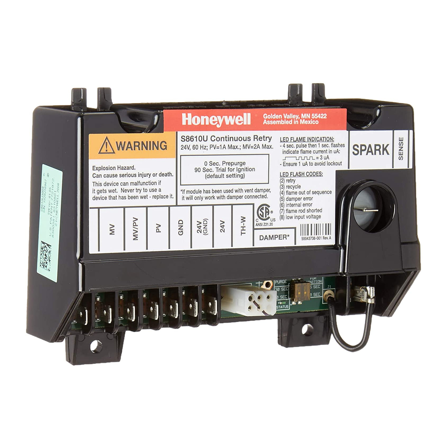
SPARK
TH-W (OPT.)
REMOTE
MV
24V (OPT.)
SENSE
MV/PV
SENSE
PV
JUMPER
BRN/GND
WIRE
24V GND
P1 VENT DAMPER
CONNECTOR
M29890
Fig. 1. Typical wiring connections.
69-2042-01
Table 1. Typical Wiring Connections.
Connector
Size or
Label
Type
Description
MV
1/4 inch
Main Valve connection
MV/PV
1/4 inch
Common terminal for gas valves
PV
1/4 inch
Pilot Valve connection
BRN GND
1/4 inch
Burner Ground
24V GND
1/4 inch
Return path to transformer
24V
1/4 inch
Optional—
24 Vac power connection for Vent
Damper
TH-W
1/4 inch
Connector for "Call for Heat" signal
from thermostat
P1
6-pin
Connector for Vent Damper
keyed plug
connection (used to control a
connected damper in atmospheric
appliances)
METER (μA)
Ammeter
Connection for ammeter probes for
probes
measuring flame current in μAmp DC.
SENSE
Wire with
Connects to the REMOTE SENSE
JUMPER
3/16 inch
connector for installations with a single
WIRE
quick
spark rod (local flame sensing)
connect
NOTE: For installations with remote
flame sensing (separate spark and
sensor rods), this jumper wire is
clipped as close to the circuit board as
possible and the wire is discarded.
REMOTE
3/16 inch
Flame Sensor connector
SENSE
For single rod installations, connect
the SENSE JUMPER WIRE to this
terminal connector.
For dual rod installations, connect the
flame sense wire from the burner/
igniter to this terminal connector.
SPARK
1/4 inch
High voltage sparking electrode
69-2042—01
2
SETTINGS AND ADJUSTMENTS
DIP Switch (S1) Settings
When replacing an existing ignition control with the S8610U,
refer to 69-1955 for the correct DIP switch settings.
IMPORTANT
Do not power the ignition control prior to setting
the DIP switches.
The following timing parameters may be set with this 2-position
DIP switch.
Prepurge
To select Prepurge, set SW1 according to Table 2.
Trial for Ignition (TFI)
To select the Trial for Ignition timing, set SW2 according to
Table 2.
Table 2. DIP Switch (S1) Settings.
Prepurge
Trial For Ignition
SW1
SW2
None
90 seconds
OFF
OFF
30 seconds
90 seconds
ON
OFF
None
15 seconds
OFF
ON
30 seconds
15 seconds
ON
ON
69-2042—01
3
S1 DIP SWITCH
M29894
Fig. 2. DIP Switch (S1) Location.
S1
ON
1
2
M23587
Fig. 3. DIP Switch (S1) - shown with factory default
settings (OFF) for SW1 and SW2.
69-2042—01
4
LED STATUS AND
TROUBLESHOOTING
The ignition control module has one LED used for flame
sensing and system status.
M29896
STATUS LED
Fig. 4. Location of LED.
69-2042—01
5
Advertisement
Table of Contents

Related Manuals for Honeywell S8610U


Summary of Contents for Honeywell S8610U
- Page 1 BRN GND 1/4 inch Burner Ground the DIP switches. The following service procedure provides a quick overview for the S8610U series control. For more information, refer to form 24V GND 1/4 inch Return path to transformer 69-1955. The following timing parameters may be set with this 2-position 1/4 inch Optional—...
- Page 2 - A single flash code number signifies that the LED flashes X times at 2 Hz, remains off for two seconds, and then repeats the sequence. customer.honeywell.com ® U.S. Registered Trademark © 2010 Honeywell International Inc. 69-2042—01 M.S. Rev. 09-10 Printed in U.S.A.
Need help?
Do you have a question about the S8610U and is the answer not in the manual?
Questions and answers
I get 5 quick flashes from control board, damper error this furnace has no damper. works for a day then quirte s. this is my 2nd control and same results?
5 quick flashes on the Honeywell S8610U control board indicate a "Damper Error." If there is no damper in the system, this error could occur due to the absence of a damper jumper on the control or a potential issue with the control module itself. You may need to verify if the jumper is in place (if required) or consider replacing the control module if it is malfunctioning.
This answer is automatically generated