Table of Contents
Advertisement
Quick Links
ENG
USE AND MAINTENANCE MANUAL
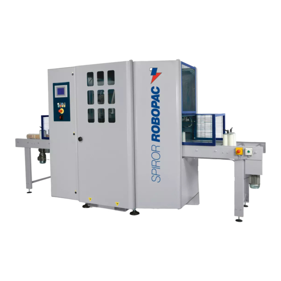
Automatic rotating ring wrapping machine with single (HP) or double (DR) plastic
film reel
SPIROR HP - DR
Translation of the original instructions
3709303158.0
Code:
0917
Edition:
____________ SERIAL NUMBER ____________
ATTENTION
Read and understand these instructions before using the machine.
Keep this handbook for further consultation.
ROBOPAC S.p.A.
Advertisement
Table of Contents

Related Manuals for Robopac SPIROR HP


Summary of Contents for Robopac SPIROR HP
- Page 1 USE AND MAINTENANCE MANUAL Automatic rotating ring wrapping machine with single (HP) or double (DR) plastic film reel SPIROR HP - DR Translation of the original instructions 3709303158.0 Code: 0917 Edition: ____________ SERIAL NUMBER ____________ ATTENTION Read and understand these instructions before using the machine.
-
Page 2: Table Of Contents
SAFETY DEVICE DESCRIPTIONS 3.4. DESCRIPTION OF THE ELECTRICAL DEVICES 3.5. PNEUMATIC DEVICE DESCRIPTION 3.6. ACCESSORIES AVAILABLE UPON REQUEST 3.7. TECHNICAL SPECIFICATIONS (Spiror HP - Spiror DR) 3.7.1. PRODUCT SIZE 3.7.2. FILM SPECIFICATIONS 3.7.3. MACHINE DIMENSIONS 3.8. SURROUNDING AREAS 3.9. NOISE LEVEL 3.10. - Page 3 SPIROR HP - DR INFORMATION ON ADJUSTMENTS 5.1. RECOMMENDATIONS FOR ADJUSTMENTS 5.2. PRESSURE PLATEN PRESSURE ADJUSTMENT 5.3. FILM WRAPPING TENSION - ADJUSTMENT 5.4. GUIDE UNITS ADJUSTMENT 5.4.1. PNEUMATIC GUIDES ON ONE SIDE 5.4.2. MANUAL SELF-CENTRING GUIDES ABOUT THE USE 6.1.
- Page 4 FILM CUTTING BLADE REPLACEMENT 9.3. REPLACE ROTATING RING BELT 9.4. FUSE REPLACEMENT 9.5. LIST OF ESSENTIAL SPARE PARTS 9.6. MACHINE DISPOSAL AND SCRAPING 10. ENCLOSED DOCUMENTATION 10.1. WARRANTY CONDITIONS 10.2. PNEUMATIC CIRCUIT DIAGRAM SPIROR HP 10.3. PNEUMATIC CIRCUIT DIAGRAM SPIROR DR English 4/95...
-
Page 5: General Information
SPIROR HP - DR 1. GENERAL INFORMATION 1.1. PURPOSE OF THE MANUAL ― The manual is an integral part of the machine and is aimed to provide the operator the instructions for use in order to prevent and reduce the risks that arise from man-machine interface. -
Page 6: Terms And Definitions
SPIROR HP - DR Machine model. Machine’s serial number. Year of manufacture. Power supply voltage. Power supply frequency. Power supply phases. Electrical power consumption. Total installed power. Air consumption. Max. air supply pressure. Machine weight. Manufacturer’s name. 1.3. TERMS AND DEFINITIONS Some recurring terms found within the manual are described in order to provide a more complete image of their meanings. -
Page 7: Modes Of Requesting For Assistance
SPIROR HP - DR 1.4. MODES OF REQUESTING FOR ASSISTANCE The distribution network ROBOPAC is at your service for any problem that requires technical support, to order spare parts, and for whatever new type of need that can help develop your business. -
Page 8: Safety Information
SPIROR HP - DR 2. SAFETY INFORMATION 2.1. GENERAL SAFETY PRECAUTIONS ― Carefully read the “Directions for use”, paying particular attention to the “Residual risks”. ― Pay attention to the safety warnings. ― Use the machine only for the use for which it is designed. -
Page 9: Safety Warnings For Use And Operation
SPIROR HP - DR ― The electrical connections must be carried out EXCLUSIVELY by operators with particular expertise in the field of intervention. ― The operator must test the machine and check, through a general test, that the machine can be commissioned without any risk for the operator. -
Page 10: Safety Warnings On Residual Risks
SPIROR HP - DR ‒ Any type and density of liquids in fragile containers. ‒ Inflammable material. ‒ Explosive material. ‒ Any type of cans with pressurised gas. ‒ Loose and volatile powders. ‒ Any material or product not intended that could in some way result hazardous to the operator and cause damage to the machine. - Page 11 SPIROR HP - DR ‒ Limb cutting risk Do not use the machine with the guard door open (see figure). ‒ Other risks Danger of crushing of arms and legs if entering the machine from infeed or outfeed through the net protections.
-
Page 12: Safety Warnings For Regulations And Maintenance
SPIROR HP - DR 2.6. SAFETY WARNINGS FOR REGULATIONS AND MAINTENANCE ― Keep the machinery in maximum efficiency condition and perform all the scheduled maintenance operations provided for by the manufacturer. Proper maintenance will provide the best performance, a longer life span and constant compliance with safety requirements. -
Page 13: Information And Safety Signals
SPIROR HP - DR 2.8. INFORMATION AND SAFETY SIGNALS The figure indicates the position of the safety and information signs affixed to the machine. For each sign is specified the relative description. Electrical hazard warning sign: do not enter area to avoid hazards of electrical shocks or electrocution. - Page 14 SPIROR HP - DR Important Check that the plates are clearly readable, and, if necessary, replace them with new ones that shall be positioned in the same places as previously. English 14/95...
-
Page 15: Technical Information
SPIROR HP - DR 3. TECHNICAL INFORMATION 3.1. MACHINE GENERAL DESCRIPTION The machine is a rotating ring machine for spiral wrapping of long shaped products that are infed longitudinally to machine’s axis. Readily available reel of stretch film are used for wrapping. - Page 16 SPIROR HP - DR SPIROR HP SPIROR HP 300 SPIROR HP 400 - 600 English 16/95...
- Page 17 SPIROR HP - DR SPIROR HP 900 SPIROR DR SPIROR DR 400 - 600 (Optional) English 17/95...
- Page 18 SPIROR HP - DR SPIROR DR 400 - 600 SPIROR DR 900 (Optional) SPIROR DR 900 English 18/95...
-
Page 19: Description Of The Operation Cycle
SPIROR HP - DR 3.2. DESCRIPTION OF THE OPERATION CYCLE Wrapping cycles performable Product wrapping can be: "Total" wrapping The product is completely spiral wrapped with a series of extra revolutions on head and tail. "Head - tail" wrapping the product is only wrapped on head and tail. -
Page 20: Total" Wrapping
SPIROR HP - DR 3.2.1."TOTAL" WRAPPING With the product on the feed conveyor, press the “Start” button on the control panel to start the work cycle. Phase 1 ‒ The conveyor starts and moves the product towards the rotating ring. - Page 21 SPIROR HP - DR Phase 2 ‒ When the “head and tail revolution” count is completed, the conveyor restarts and product length wrapping begins. The product moves forward and engages photocell (B2), the outfeed pressure platen lowers on the product while the machine continues to wrap product.
- Page 22 SPIROR HP - DR Phase 4 ‒ After the counting of the “head and tail round” the rotating ring stops while the gripper blocks the film and the arm with the blade makes the cut. ‒ The outfeed conveyor restarts.
-
Page 23: Head - Tail" Wrapping
SPIROR HP - DR 3.2.2."HEAD - TAIL" WRAPPING With the product on the feed conveyor, press the “Start” button on the control panel to start the work cycle. Phase 1 ‒ The conveyor starts and moves the product towards the rotating ring. - Page 24 SPIROR HP - DR Phase 2 ‒ Infeed/outfeed conveyors starts. ‒ The product moves forward and engages photocell (B2). ‒ The outfeed pressure platen lowers on the product. Phase 3 ‒ The product moves forward disengaging photocell (B1), the infeed pressure platen lifts and the ring starts rotation.
- Page 25 SPIROR HP - DR Phase 4 ‒ After the counting of the “head and tail round” the rotating ring stops while the gripper blocks the film and the arm with the blade makes the cut. ‒ The outfeed conveyor restarts.
-
Page 26: Complete" Wrapping And "Central Bands
SPIROR HP - DR 3.2.3."COMPLETE" WRAPPING AND "CENTRAL BANDS" With the product on the feed conveyor, press the “Start” button on the control panel to start the work cycle. Phase 1 ‒ The conveyor starts and moves the product towards the rotating ring. - Page 27 SPIROR HP - DR Phase 2 ‒ Once the "reinforcing revolutions" count has been completed, the conveyor restarts and the product is wrapped longitudinally. ‒ The product moves forward and engages photocell (B2), the outfeed pressure platen lowers on the product while the machine continues to wrap product.
- Page 28 SPIROR HP - DR Phase 4 ‒ The product moves forward disengaging photocell (B1), the infeed pressure platen lifts, the “tail positioning” timer starts. ‒ After timer count has been completed, the outlet conveyor stops and the "reinforcing revolutions" count is started.
-
Page 29: Head-Tail" And "Central Belts" Wrapping
SPIROR HP - DR 3.2.4."HEAD-TAIL" AND "CENTRAL BELTS" WRAPPING With the product on the feed conveyor, press the “Start” button on the control panel to start the work cycle. Phase 1 ‒ The conveyor starts and moves the product towards the rotating ring. - Page 30 SPIROR HP - DR Phase 2 ‒ Infeed/outfeed conveyors starts. ‒ The product moves forward and engages photocell (B2). ‒ The outfeed pressure platen lowers on the product. Phase 3 ‒ The "central bands" timer starts counting; at count completed, the conveyor stops, the rotating ring starts and counts the "reinforcing revolutions"...
- Page 31 SPIROR HP - DR Phase 4 ‒ The product moves forward disengaging photocell (B1), the infeed pressure platen lifts and the ring starts rotation. ‒ After one revolution, conveyors turn on and the “tail positioning” timer begins counting. ‒ After the timer count has finished, the outfeed carrier stops, the “head and tail...
-
Page 32: Safety Device Descriptions
SPIROR HP - DR 3.3. SAFETY DEVICE DESCRIPTIONS Danger - Warning The safety devices must be periodically checked to ensure that they are working properly. The machine is equipped with safety devices designed to guarantee the greatest possible degree of safety and protection for the operator. -
Page 33: Description Of The Electrical Devices
SPIROR HP - DR Interlocking mobile protection; when protections are opened, machine stops. Bi-stable solenoid valves: block all the pneumatic activated movements when there is an electric voltage cut-off, whether it is caused by a blackout or by pressing the emergency button. -
Page 34: Pneumatic Device Description
SPIROR HP - DR Electric motor it starts the rotation of the cutting unit. Important For further details see the electrical diagram. 3.5. PNEUMATIC DEVICE DESCRIPTION The figure shows the positioning of the devices on board of the machine. to eliminate pneumatic pressure inside the machine. -
Page 35: Accessories Available Upon Request
You can also request belt conveyors in lengths 1500/2500/3500 mm. The conveyors can have a double function for product accumulation and further support. 3.7. TECHNICAL SPECIFICATIONS (Spiror HP - Spiror DR) The table below shows the technical specifications of the machine (Spiror HP). Description Units Value measur‑... -
Page 36: Product Size
SPIROR HP - DR Allowed pressure (max) Average air Nl/min consumption The table below shows the technical specifications of the machine (Spiror DR). Description Units Value measur‑ ement Machine Spiror DR 400 Spiror DR 600 Spiror DR 900 Supply voltage... - Page 37 SPIROR HP - DR Important The workable products must not cross the outlined area. SPIROR HP 300 SPIROR HP 400 English 37/95...
- Page 38 SPIROR HP - DR SPIROR HP 600 SPIROR HP 900 English 38/95...
- Page 39 SPIROR HP - DR SPIROR DR 400 SPIROR DR 600 English 39/95...
-
Page 40: Film Specifications
SPIROR HP - DR SPIROR DR 900 3.7.2.FILM SPECIFICATIONS Description Units of Value measurement (D) External diameter (d) Internal diameter (L) Width 125 - 250 Film thickness μm 17 ÷ 50 English 40/95... -
Page 41: Machine Dimensions
SPIROR HP - DR 3.7.3.MACHINE DIMENSIONS Spiror Spiror Spiror Spiror Spiror Spiror Spiror HP 300 HP 400 HP 600 HP 900 DR 400 DR 600 DR 900 2630 1830 1830 1311 1311 1511 1711 1311 1511 1711 English 41/95... -
Page 42: Surrounding Areas
SPIROR HP - DR 3.8. SURROUNDING AREAS Operator's working area. (∗) Product outfeed area (∗) Product infeed area Sorrounding area. (∗) These areas must be suitably sized to the product being processed. 3.9. NOISE LEVEL While working, the machine reaches the noise levels shown in the table. - Page 43 SPIROR HP - DR Operator's working area. (∗) Product outfeed area (∗) Product infeed area Sorrounding area. Compressed air connection point. Electric power point. (∗) These areas must be suitably sized to the product being processed. English 43/95...
-
Page 44: Information On Handling And Installation Operations
SPIROR HP - DR 4. INFORMATION ON HANDLING AND INSTALLATION OPERATIONS 4.1. RECOMMENDATIONS FOR HANDLING AND LOADING Important Accomplish handling and loading according to the instructions supplied by the manufacturer to be found on the machine and in the operating instructions. The person authorized to accomplish these operations must, if necessary, organise a "safety plan"... -
Page 45: Transport And Handling
SPIROR HP - DR Spiror Spiror Spiror Spiror Spiror Spiror Spiror HP 300 HP 400 HP 600 HP 900 DR 400 DR 600 DR 900 2000 2000 2000 2000 2000 2000 2000 1700 1700 1700 1900 1700 1700 1900 2020... -
Page 46: Unpack
SPIROR HP - DR 4.5.1.UNPACK Take off the cover. Remove the fasteners from all components (plastic strip or wooden dolly blocks). Check to see that all the material is there, and that it is not damaged in any way. Important You are advised to keep the packaging material. -
Page 47: Assembly Of The Product Infeed Units (L = 1500 / 2500)
SPIROR HP - DR 4.5.3.ASSEMBLY OF THE PRODUCT INFEED UNITS (L = 1500 / 2500) With machine equipped with belt infeed units, remove the safety protection panel (A). Assemble the vertical guide units, if available (optional). Operation to be carried out only with roller infeed units. -
Page 48: Assembly Of Safety Protections
SPIROR HP - DR Connect the power supply wires of the photocells by screwing in connectors. Connect wires to terminals of electric motors. Important If the rotation sense of the rollers is incorrect, invert the phases on the terminal box of the motor. -
Page 49: Pneumatic Connections
SPIROR HP - DR 4.7. PNEUMATIC CONNECTIONS Proceed as indicated. Insert a flexible tube on the end of the rubber fitting and fasten it with a metallic screw clamp (A). Check that the valve (B) is in the "OPEN" position. -
Page 50: Information On Adjustments
SPIROR HP - DR 5. INFORMATION ON ADJUSTMENTS 5.1. RECOMMENDATIONS FOR ADJUSTMENTS ‒ Before performing any operation, the authorised operator must make sure that he/she understood the "Instructions for use". ‒ Pay attention to the SAFETY WARNINGS, do not use the machine for UNSPECIFIED PURPOSES and assess the possible RESIDUAL RISKS. -
Page 51: Film Wrapping Tension - Adjustment
SPIROR HP - DR 5.3. FILM WRAPPING TENSION - ADJUSTMENT Loosen nut (A) and rotate flange (B); by turning clockwise the roller’s braking effect increases therefore wrapping tension. Adjustment is very sensitive, therefore turn the flange of just a few revolutions to obtain the desired effect. -
Page 52: About The Use
SPIROR HP - DR ABOUT THE USE 6.1. RECOMMENDATIONS FOR OPERATION AND USE ‒ Before performing any operation, the operator must make sure that he/she understood the "Instructions for use". ‒ When using the machine for the first time, the operator must read the manual and identify the controls and simulate some operations, especially the start-up and shutdown. -
Page 53: Using The Panel
SPIROR HP - DR The blue buttons are the ones that can be pressed (functional buttons), while the gray ones are inactive and only for display. 6.3.1.USING THE PANEL Switching on the machine the introduction page is displayed. It contains. -
Page 54: Main Page
SPIROR HP - DR ‒ Choose the recipe (type of processing operation desired) by touching one of the keys and confirm by touching key (B) (to set the recipe see “Cycle parameters setting”). The machine is ready to run in automatic mode all the cycle parameters displayed on the main screen. -
Page 55: Operator And Password Change Key
SPIROR HP - DR 6.3.3.OPERATOR AND PASSWORD CHANGE KEY Some settings can only be accessed by the machine Manager after entering the password (editable), in order to prevent unauthorized personnel from changing the password. Caution - Warning The factory responsible should assign... -
Page 56: Default Password Reset
SPIROR HP - DR If correct, confirm by tapping the key (F) and confirm again in the pop UP window by tapping the key (G). 6.3.4.DEFAULT PASSWORD RESET If you need to restore the default password in case you have forgotten the... -
Page 57: General Parameters Settings
SPIROR HP - DR 6.3.5.GENERAL PARAMETERS SETTINGS Press the key (C) from the main screen to open the “General parameters” screen. ‒ Press the key (1) to open the “Production counters” screen. ‒ Press the key (2) to open the “H.M.I. - Page 58 SPIROR HP - DR ‒ Press the key (3) to open the “Login password” window (See “Operator change“). ‒ Tap the key (4) to open the password change window (See “Password change “). ‒ Tap the key (5) to open the “product loading and unloading”...
-
Page 59: Software Settings And Displays
SPIROR HP - DR 6.3.6.SOFTWARE SETTINGS AND DISPLAYS ‒ Tap the key (C) from the main screen to open the general parameters screen. ‒ Tap the key (2) to open the “H.M.I Permissions” screen. English 59/95... - Page 60 SPIROR HP - DR 2.1) Set the light intensity of the display. 2.2) See the software version information. 2.3) To set the date and time,. English 60/95...
- Page 61 SPIROR HP - DR 2.4) Display information on machine status for assistance purposes. 2.5) Display a summary of machine last alarms tripped. 2.6) Enable / disable the sound by pressing the keys. ‒ Change the various parameters, confirm with "ESC" push-button (A).
-
Page 62: Date And Time Setting
SPIROR HP - DR 6.3.7.DATE AND TIME SETTING For this operation proceed in the following way. Display the main page (see “Operating terminal description” - “Main screen“). Tap the key (C) to open the general parameters screen. Touch the key (3) and... -
Page 63: Modification Mode Regarding The Settings
SPIROR HP - DR Rotation of the reel change / wheel. Incoming product pressure unit ascent/descent. Outgoing product pressure unit ascent/descent. The product infeed/outfeed pulling unit forward/backward. Clamping unit exit/retraction. Upward/downward of the welder/rubber on the stopper. Exit/return rotating cut-off. -
Page 64: Written Editings And Values
SPIROR HP - DR 6.4.1.WRITTEN EDITINGS AND VALUES The keypad is displayed each time the editable or programmable functions are enabled. Digit the requested value or name and confirm by pressing the "Enter" (1) key. Touch the "Esc" (2) key to disable the editing mode. -
Page 65: Copy Recipes" Function
SPIROR HP - DR 6.4.3.“COPY RECIPES” FUNCTION For this operation proceed in the following way: Display the main page (See "Main screen"). Press key (A) to view the list of recipes. Press the key (B) to open the “Copy Recipes” screen. -
Page 66: Cycle Parameter Setting (Recipe Composition)
SPIROR HP - DR 6.5. CYCLE PARAMETER SETTING (RECIPE COMPOSITION) For this operation proceed in the following way. Display the main page (see “Operating terminal description” - “Main screen“). Tap the key (C) to open the general parameters screen. Touch the key (3) and access via password, as machine manager (see “Operating terminal description”... - Page 67 SPIROR HP - DR Press the keys "+" or "-" to increase or decrease the value of the parameter. The graphic bar represents the value set for admitted values (see “Setting modification procedure”). Touch the key (Z) to return to the previously displayed page.
- Page 68 SPIROR HP - DR The parameters of the wrapping cycle are the following: Winding number (variable from 1 to Allows to set the additional number of rpm that need to be carried out at the beginning of the wrapping cycle (top of product).
- Page 69 SPIROR HP - DR Product winding start time (head). This is the time that determines the winding start position relative to the beginning of the product. Rotating ring and carriers speed function. ‒ Rotating ring speed function. To increase or decrease rotating ring speed;...
- Page 70 SPIROR HP - DR Product winding end time (tail). This is the time that determines the winding end position relative to the end of the product. Important To rename the recipe, you must touch key (A). Upon viewing the keypad, follow the instructions in section "Modifying...
-
Page 71: Wrapping Cycle Reset
SPIROR HP - DR 6.6. WRAPPING CYCLE RESET If the machine is stopped or turned off during winding of a product using the START button, winding can be resumed from where it was interrupted by restarting the cycle without other operations. -
Page 72: Putting The Rotating Ring In Phase
SPIROR HP - DR ― All safety devices must be integral and efficient. ― The machine must be cleaned and in order. ― Compressed air supply must be open and pressure adjusted to 6 bar. ― The film reel must be sufficiently full to guarantee operations (See "Coil replacement"). - Page 73 SPIROR HP - DR Open the door (D) to access the reel. Press the button and take out flange (E). Insert the reel on mandrill, put flange back on and repress the button. Important The adhesive side of the film must always face the product to be wrapped.
- Page 74 SPIROR HP - DR For models HP 400 - HP 600 - HP 900 Manually open the clamp and insert the film end between the jaws. Close the protection. Press the “Reset” button. For model HP 300 Close the protection.
-
Page 75: Insert The Film In The Clamp
SPIROR HP - DR For models DR 400 - DR 600 - DR 900 Close the protection. Press the “Reset” button. Open the protection. Tie-up the films' edges of the reels. Press the "reset" button followed again by the “film insertion” button (F). -
Page 76: Cycle Start
SPIROR HP - DR Open protection (B). Manually unroll a metre of film and let it pass under and resting on the (C) gripper bar. Close protection (B) holding the film tight with your right hand. With your left hand push the Reset button (E). -
Page 77: Types Of Stopping And Starting
SPIROR HP - DR 6.11. TYPES OF STOPPING AND STARTING During operation there can be voluntary or unforeseen conditions that stop the machine. These are the possibilities: ― temporary stop (voluntary). ― electric black-out stop. ― production end stop. ―... -
Page 78: Production End Stop
SPIROR HP - DR 6.11.3. PRODUCTION END STOP This situation verifies when the work shift or machine use is over or when the machine remains inactive or not attended to for a certain lapse of time. Turn the main switch (IG) to position "0". -
Page 79: Maintenance Information
SPIROR HP - DR 7. MAINTENANCE INFORMATION 7.1. MAINTENANCE INSTRUCTIONS ― Before performing any operation, the authorised operator must make sure that he/she understood the "Instructions for use". ― Pay attention to the SAFETY WARNINGS, do not use the machine for UNSPECIFIED PURPOSES and assess the possible RESIDUAL RISKS. - Page 80 SPIROR HP - DR Every 2000 Rotating ring General Check for wear hours belt inspection and, if necessary, replace Contact the Servicing Department. Every 2000 Rotating ring General Tension See "Rotating hours belt inspection adjustment Ring Belt - Adjustment". Every 2000...
-
Page 81: Lubrication Point Diagram
SPIROR HP - DR 7.3. LUBRICATION POINT DIAGRAM Lubricate the illustrated parts at the time and with the methods indicated. English 81/95... -
Page 82: Lubricants Table
SPIROR HP - DR Smear with grease Inject grease. Keep to the recommended lubrication frequency to get top machine performances and a longer operating life. Use lubricants (oils or grease) recommended by the manufacturer or with similar chemical- physical features. -
Page 83: Draining The Condensate
SPIROR HP - DR Mineral oil +32°C/+50°C -460 CST/40°C Worm gear motor MELLANA OIL 460 IP SPARTAN EP 460 ESSO BLASIA 460 AGIP MOBILGEAR 634 MOBIL OMALA EP 460 SHELL ENERGOL GR-XP 460 BP Grease TELESIA COMPOUND B IP Gear and worm gear motor... -
Page 84: Rotating Ring Belt - Adjustment
SPIROR HP - DR 7.7. ROTATING RING BELT - ADJUSTMENT Loosen nut (A). Adjust the tension of the belt by operating on the (B) nuts. Once adjustment has been performed, tighten nut (A). 7.8. PRODUCT INFEED UNIT CHAIN - ADJUSTMENT Loosen nut (A). -
Page 85: Machine Cleaning
SPIROR HP - DR 7.9. MACHINE CLEANING General cleaning of the machine is fundamental to guarantee efficiency in the long run. All the machine must be kept free from dust, dirt and foreign bodies. The chromed shafts must be cleaned with a cloth and slightly lubricated with a cloth soaked in Vaseline oil. -
Page 86: Troubleshooting
SPIROR HP - DR 8. TROUBLESHOOTING 8.1. SOME SUGGESTIONS ON OPERATION The following is some trouble shooting that might occur during operation and its solution. Problem Remedy Film is too loose during the wrapping Increase the braking effect of the operation. - Page 87 SPIROR HP - DR E10 PROTECTION COVER OPEN ALARM Cause: - Protection cover open. Remedy: - Close the cover and press the Reset button. Cause: - Limit switch malfunction. Remedy: - replace power switch. E15 WARNING “DOOR VIOLATION CHECK ALARM”...
- Page 88 SPIROR HP - DR E62 “GRIPPER NOT IN POSITION” ALARM Cause: - Clamp cylinder magnetic sensors not properly working. Remedy: - Check and replace the sensor if necessary. E63 "CLAMP CLOSED" ALARM Cause: - Clamp cylinder magnetic sensors not properly working.
-
Page 89: Spare Parts Replacement Information
SPIROR HP - DR 9. SPARE PARTS REPLACEMENT INFORMATION 9.1. RECOMMENDATIONS FOR REPLACING PARTS ‒ Carry out the interventions with all the safety devices enabled and wear the DPI provided. ‒ DO NOT carry out any intervention that is not described in the manual but contact an Assistance Service authorised by the manufacturer. -
Page 90: Replace Rotating Ring Belt
SPIROR HP - DR 9.3. REPLACE ROTATING RING BELT Slacken the belt (A). Remove the belt from its housing. Insert the new belt. tighten the belt (See "Rotating Ring Belt - Adjustment"). 9.4. FUSE REPLACEMENT Note Work that must be performed mandatorily by a specialised operator. -
Page 91: Machine Disposal And Scraping
SPIROR HP - DR 9.6. MACHINE DISPOSAL AND SCRAPING Important These operations must be performed by specialised personnel in accordance with the standards in force on workplace safety. Do not scatter non biodegradable products, lubricant oil and non-iron components (rubber, PVC, resins, etc.) in the environment.). -
Page 92: Enclosed Documentation
To utilise the warranty, the user must immediately notify the company that a defect exists, always referring to the machine serial number. ROBOPAC S.p.A., in its final judgement, will decide whether to replace the defective part or request it to be shipped for tests and/or repairs. -
Page 93: Pneumatic Circuit Diagram Spiror Hp
SPIROR HP - DR 10.2. PNEUMATIC CIRCUIT DIAGRAM SPIROR HP Air treatment unit. Solenoid valve. Presser drive pneumatic cylinder. Adjust / Pressure units thrust manometer. Open/close clamp pneumatic cylinder. Pneumatic cylinder forward / clamp backward. Self-centring guides pneumatic cylinder (optional). -
Page 94: Pneumatic Circuit Diagram Spiror Dr
SPIROR HP - DR 10.3. PNEUMATIC CIRCUIT DIAGRAM SPIROR DR Air treatment unit. Solenoid valve. Presser drive pneumatic cylinder. Adjust / Pressure units thrust manometer. Open/close clamp pneumatic cylinder. Pneumatic cylinder forward / clamp backward. Self-centring guides pneumatic cylinder (optional). - Page 95 EC DECLARATION OF CONFORMITY (Annex IIA DIR. 2006/42/EC) Robopac S.p.A. Via Fabrizio da Montebello, 81 - 47892 Gualdicciolo Republic of San Marino DECLARES THAT THE MACHINE ROBOPAC MACHINERY Robopac S.p.A. Via Fabrizio da Montebello, 81 47892 – Gualdicciolo Repubblica di San Marino http://www.robopac.com/...
Need help?
Do you have a question about the SPIROR HP and is the answer not in the manual?
Questions and answers