Table of Contents
Advertisement
Quick Links
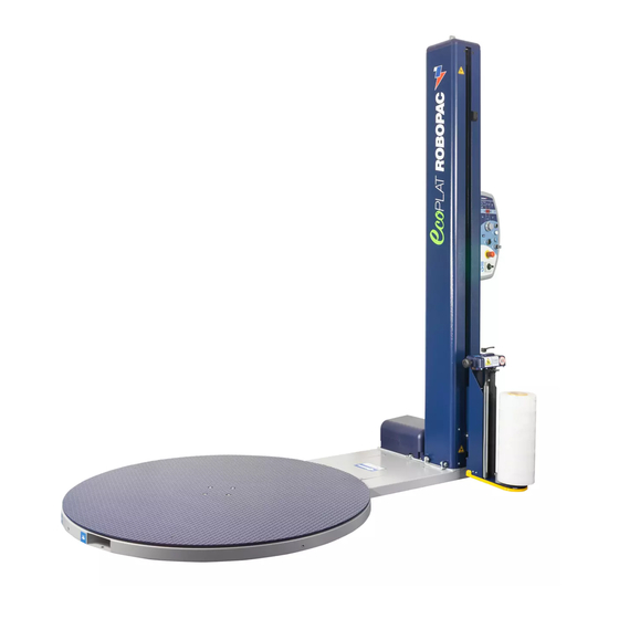
ECOPLAT PLUS BASE
ECOPLAT PLUS FRD
ECOPLAT PLUS FRD USA
N. matricola • Serial number • Serienummer
N. d'identification • Matricula n.
Cod.: 3709304595
ROBOPAC S.p.a
Via Fabrizio da Montebello, 81
47892 Repubblica di San Marino
Phone (+378) 0549 910511
Fax (+378) 0549 908549
Ed.: 19.02
Translation of original instructions
ENG
Advertisement
Table of Contents


Need help?
Do you have a question about the ECOPLAT PLUS BASE and is the answer not in the manual?
Questions and answers