
Related Manuals for COMFORT-AIRE RADS Series


Summary of Contents for COMFORT-AIRE RADS Series
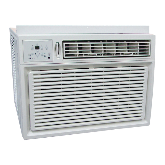
- Page 1 Owner’s Manual RADS Series Window Type Room Air Conditioner RADS-183R RADS-253R www.marsdelivers.com...
-
Page 3: Table Of Contents
Table of Contents IMPORTANT SAFETY INSTRUCTIONS .........04 1.Warning .....................................04 2.Caution .....................................05 3.Operation of Current Device ............................07 INSTALLATION INSTRUCTIONS ...........08 1.Installation Instructions(for 5000 to 12000Btu/h) ....................09 2.Installation Instructions(for 15000 to 28500Btu/h) .....................14 A.Window Mounting .................................15 B.Thru-The-Wall Installation ................................20 C.Masonry Construction ..............................21 NORMAL SOUNDS ...............22 AIR CONDITIONER FEATURES... -
Page 4: Important Safety Instructions
IMPORTANT SAFETY INSTRUCTIONS READ THIS MANUAL Inside you will nd many helpful hints on how to use and maintain your air conditioner properly. Just a little preventive care on your part can save you a great deal of time and money over the life of your air conditioner. -
Page 5: Caution
CAUTION When the air lter is to be removed, do not touch the metal parts of the unit. It may cause an injury. Do not put a pet or house plant where it will be exposed to direct air ow. This could injure the pet or plant. - Page 6 NOTE: The power supply cord with this air conditioner contains a current detection device designed to reduce the risk of re. Please refer to the section Operation of Current Device for details.In the event that the power supply cord is damaged, it cannot be repaired-it must be replaced with acord from the Product Manufacturer.
-
Page 7: Operation Of Current Device
Operation of Current Device (Applicable to the unit adopts current detection device only ) The power supply cord contains a current device that senses damage to the power cord. To test your power supply cord do the following: 1.Plug in the Air Conditioner. 2.The power supply cord will have TWO buttons on the plug head. -
Page 8: Installation Instructions
INSTALLATION INSTRUCTIONS NOTE: The unit you purchased may be look like one of the followings: NOTE: All the illustrations in this manual are for explanation purpose only. The air conditioner you have may be slightly di erent. The actual shape shall prevail. ... -
Page 9: Installation Instructions(For 5000 To 12000Btu/H)
Installation Instructions (for 5000 to 12000Btu/h) BEFORE YOU BEGIN Read these instructions completely and carefully. 6000~8000Btu/h 10000~12000Btu/h 5000~6000Btu/h Model MPORTANT-Save these instructions for local inspector’s use. 14 (356mm) 15-1/2 (394mm) 13 (330mm) IMPORTANT-Observe all governing codes Table 1 and ordianaces. Note to Installer- Be sure to leave these CAUTION instructions with the Consumer. - Page 10 C: Align the hole in the top rail with those in the PREPARE THE WINDOW top of the unit as shown in Fig.B Lower sash must open su ciently to allow a clear Fig.B vertical opening of 13 inches (330mm). Side louvers and the rear of the AC must have clear air space to allow enough air ow through the condenser, for heat removal.
- Page 11 B. Slide the free end " I" section of the panel SECURE THE ACCORDION PANELS directly into the cabinet as shown in Fig. 2. Slide the panel down. Be sure to leave enough space A.Keep a rm grip on the air conditioner, to slip the top and bottom of the frame into the carefully place the unit into the window rails on the cabinet.
- Page 12 INSTALL R1 HARDWARE (only applicable to ≥15000Btu/h Energy star models ) In order to minimize air leaks and ensure optimal insulation, it is necessary to install the included Fig.7A Fig.7B R1 hardware to the side curtain. Follow the instructions below. DRIVE LOCKING SCREWS Step 1.
- Page 13 Step 3. Slide the R1 insulation panel into the side If AC is Blocked by Storm Window curtain, the side with pattern should facing the indoor side.(Fig.13) Add wood as shown in Fig.15, or remove storm window before air conditioner is installed.
-
Page 14: Installation Instructions(For 15000 To 28500Btu/H)
Preliminary Instructions Installation Instructions (for 15000 to 28500Btu/h) Window Sash Seal Safety Lock and 3 /4 (or1/2 ) Long Hex Head Screw BEFORE YOU BEGIN Top Angle Foam Gasket Read these instructions completely and Washer Head Locking screw carefully. IMPORTANT-Save these instructions for Frame Assembly (Left) -
Page 15: A.window Mounting
3. Check your storm windows-- if your storm A. Window Mounting window frame does not allow the clearance required, correct by adding a piece of wood Remove Air Conditioner from Cabinet as shown in Fig.E,or by removing storm window NOTE: Remove any packaging material from while room air conditioner is being installed. - Page 16 10. Your unit may come with internal packaging. Air Conditioner Plastic Cabinet This packaging must be removed prior to installing Frame View the air conditioner back into the cabinet.(see Fig .7). Locking Screw "Ⅰ" Section Shipping Packaging Hole Window Filler Panel Fig.10 Plastic tie...
- Page 17 1 2 Long Screws Left And Locknuts 3 4 (or1 )Long Hex-head Screw Locknut Sill Angle Right Bracket Flat Head Bolt Fig.13 Fig.13B 2 Each Required For Each Support Bracket Install Support Bracket Fig.15B 1. Hold each support bracket ush against outside 3.
- Page 18 4. Attach the top angle to window frame: Use a 3. Attach the Lock Frames to the winow sill 3/32" drill bit to drill one hole through the hole using two 3/ 4 " (19mm) screws(Fig.18C) in the middle of top angle into the window frame, (on some models) and drive one 3/ 4 "...
- Page 19 Install Chassis into Cabinet and Install Front to Unit 1. Lift air conditioner and carefully slide into cabinet leaving 6 inches protruding. 2. DO NOT push on controls or nned coils. 3. Be sure chassis is rmly seated towards rear of cabinet.
-
Page 20: B.thru-The-Wall Installation
WIDTH " X"= inside model width plus twice the B. Thru-The-Wall Installation thickness of framing material used. HEIGHT '' Y " = inside model height plus twice the NOTE: Consult local building codes prior to thickness of framing material used. installation or a quali ed carpenter. -
Page 21: C.masonry Construction
5. Screw or nail cabinet wooden frame using shims Prepare and Install Cabinet if frame is oversized to eliminate distortion. See 1. Slide chass is from cabinet. Refer back to Fig.8.Remember to maintain proper slope as Step one of Window Mounting. described in Step 3. -
Page 22: Normal Sounds
NORMAL SOUNDS Pinging or Switching Vibration Droplets of water hitting condenser during High Pitched Chatter normal operation may cause “pinging or Unit may vibrate and make noise swishing” sounds. This noise can be reduce by because of poor wall or window High e ciency compressors “construction or incorrect ”installation. -
Page 23: Air Conditioner Features
AIR CONDITIONER FEATURES To begin operating the air conditioner, WARNING follow these steps: 1. Set the thermostat to the highest number To reduce the risk of re, electric shock, or (coldest or cooler setting). injury to persons, read the IMPORTANT 2. -
Page 24: Mechanical Control Operating Instructions
Fresh Air Vent Control (on 15~28.5K models): Fig. A Fig. B Fig. C (VENT CLOSED) (VENT OPEN) (VENT & EXHAUST OPEN) The Fresh Air Vent allows the air conditioner to: 1. Recirculate inside air - Vent Closed (See Fig.A) 2. Draw fresh air into the room- Vent Open (see Fig.B) 3. -
Page 25: Electronic Control Operating Instructions
ELECTRONIC CONTROL OPERATING INSTRUCTIONS NOTE: Di erent models have di erent control buttons and indicator lights. Not all the control buttons and indicator lights describing below are available for the unit you purchased. Please check the control panel of the unit you purchased. The unit can be controlled by the unit control alone or with the remote. TEMP/TIMER Auto Auto... - Page 26 FOLLOW ME FEATURE: SLEEP FEATURE: (on some models) Press Sleep button to initiate the sleep mode. Light flashes or In this mode the selected temperature will illuminates Follow ° increase (cooling) or decrease (heating) by 2 ° (or 2) C 30 minutes after the mode is selected. This feature can be activated from the remote The temperature will then increase (cooling) or control ONLY.
- Page 27 • Turning the unit ON or OFF at any time or a To operate on Auto feature: djusting the timer setting to 0.0 will cancel the • When you set the air conditioner in AUTO mode, it will automatically select cooling, heating(cooling Auto Start/Stop timed program.
-
Page 28: Care And Cleaning
CARE AND CLEANING The air lter should be checked at least once a CAUTION month to see if cleaning is necessary. Trapped particles in the lter can build up and cause an Clean your air conditioner occasionally to accumulation of frost on the cooling coils. keep it looking new. -
Page 29: Troubleshooting Tips
TROUBLESHOOTING TIPS Before calling for service, review this list. It may save your time and expense. This list includes common occurrences that are not the result of defective workman-ship or materials in this appliance. Problem Solution Air conditioner Wall plug disconnected. Push plug rmly into wall outlet. does not start House fuse blown or circuit breaker tripped. - Page 30 Problem Solution Water dripping Improper installation. Tilt air conditioner slightly to the outside to allow water drainage. INSIDE when unit Refer to installation instructions - check with installer. is cooling. Water dripping Unit removing large quantity of moisture from humid room. This is normal during OUTSIDE when excessively humid days.
- Page 31 Comfort-Aire shall have the right to allow a credit in the amount of the current suggested retail price of the product instead LIMITED ONE (1) YEAR EXPRESS WARRANTY of providing replacement.
- Page 32 Owner’s Manual - RADS Series 1900 Wellworth Ave., Jackson, MI 49203 • Ph. 517-787-2100 • www.marsdelivers.com...
Need help?
Do you have a question about the RADS Series and is the answer not in the manual?
Questions and answers