
Subscribe to Our Youtube Channel
Related Manuals for Uflex UC 69-I


Summary of Contents for Uflex UC 69-I
- Page 1 Installation and Maintenance Manual HYDRAULIC CYLINDERS FOR INBOARD ENGINES UC 69-I UC 168-I UC 116-I UC 215-I UC 293-I PARTNER (Dr. No. 31851/b 29/05/2020)
- Page 2 2013/53/EU. "Established in 1989 UFLEX USA is a leader in steering and control systems for the marine industry. With full manufacturing capabilities in Sarasota, Florida, UFLEX USA can support all sectors of the marine industry regardless of volume and/or product requirements.
-
Page 3: Table Of Contents
Installation and Maintenance Manual TABLE OF CONTENTS MANUAL USE AND SYMBOLS USED........................4 INTRODUCTION..........................5 WARRANTY..........................5 SECTION 1 - PRODUCT DESCRIPTION HYDRAULIC STEERING SYSTEM OPERATION..................7 WARNINGS FOR THE CORRECT PRODUCT USE ..............7 CYLINDER DESCRIPTION......................8 TECHNICAL FEATURES..........................8 CYLINDER CHOICE............................9 SECTION 2 - TRANSPORT GENERAL WARNINGS..........................10 PACKAGING CONTENTS........................10 SECTION 3 - INSTALLATION... -
Page 4: Manual Use And Symbols Used
Installation and Maintenance Manual MANUAL USE AND SYMBOLS USED THE INSTALLATION AND MAINTENANCE MANUAL is the document accompanying the product from its sale to its replacement and discharge. The manual is an important part of the product itself. It is necessary to read carefully the manual, before ANY ACTIVITY involving the product, handling and unloading included. -
Page 5: Introduction
1. Two Year Limited Warranty. UFLEX USA, Inc. warrants that all products manufactured by UFLEX USA, Inc. or ULTRAFLEX S.p.A. and sold by UFLEX USA to the retail purchaser ("Purchaser") that for two (2) years after the date of manufacture to be free from defects due to material or workmanship, subject to the exclusions below. - Page 6 If we are unable to resolve the problem UFLEX will issue a Return Goods Authorization number and we require that the product in question be returned to UFLEX with all its parts in its original packaging. The product should be returned freight prepaid to:...
-
Page 7: Section 1 - Product Description
UC 69-I, UC 116-I, UC 168-I, UC 215-I and UC 293-I cylinders must not be installed on race boats. WARNING Cylinder UC 69-I can be installed on inboard engines up to 150 hp and only with single cylinder and single helm. WARNING... -
Page 8: Cylinder Description
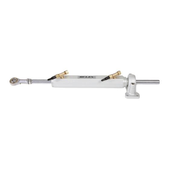
Installation and Maintenance Manual 1.3 Cylinder description The hydraulic cylinders for inboard engine UC 69-I, UC 116-I, UC 168-I, UC 215-I and UC 293-I models have been designed and manufactured to be used as a component in the hydraulic steering systems, as described in the previous paragraph. -
Page 9: Cylinder Choice
150 mm 30° 130 mm [5.12"] 420 Nm 210 Nm 6" 30° 133 mm [5.22"] 429 Nm 215 Nm UC 69-I 130 mm 35° 106 mm [4.18"] 343 Nm 172 Nm 5" 36° 102 mm [4.03"] 331 Nm 166 Nm 180 mm 30°... -
Page 10: Section 2 - Transport
Installation and Maintenance Manual 2 TRANSPORT 2.1 General warnings The product weight with its packaging is about 9kg (19 pounds) and so it can be handled manually. WARNING The staff in charge of handling must operate with protective gloves and safety shoes. 2.2 Packaging contents Before using the equipment check that the product has not been damaged during transport. -
Page 11: Section 3 - Installation
Installation and Maintenance Manual 3 INSTALLATION 3.1 Necessary tools Torque Open end Open end Open end Open end Open end Open end wrench wrench wrench wrench wrench wrench wrench 13 mm 3/4" 10 mm 17 mm 22 mm 15/16" 3.2 Cylinder installation DANGER An arm shorter than the one indicated could move the helm instead of the cylinder up to the end stroke by causing the breaking of the steering guide and the following loss of boat control. - Page 12 10 Nm using a 10 mm wrench (for bolt and nut M6 UC 69-I) or of 25 Nm with a 13 mm wrench (for bolt and nut M8 UC 116-I, 168-I, 215-I, 293-I).
-
Page 13: Hose Installation
W rench to tighten the W rench to tighten the Ball joint hole diameter space allowed (A) the safety lock nut (4) safety lock nut (4) ball joint (3) UC 69-I 19 mm [3/4"] 50 Nm 17 mm 17 mm 10 mm UC 116-I 22 mm [7/8"]... -
Page 14: Type Of Installation
Connect hoses as shown in the following pictures: The UC 69-I (only single station and single helm), UC 116-I, UC 168-I, UC 215-I and UC 293-I hydraulic cylinders for inboard engines can be installed with different configurations according to the number and the type of engines used with a single or dual steering system. - Page 15 Installation and Maintenance Manual DUAL STATION / SINGLE CYLINDER: DUAL STATION / SINGLE CYLINDER WITH DUAL HELM: 1. main steering 4. T fittings with bleed 1. main steering 4. T fittings with bleed station valves station valves 2. a d d i t i o n a l 5.
-
Page 16: Filling And Purging
- Mobil DTE 11M NOTICE UFLEX will not be able to ensure the compatibility of the above mentioned oils with OIL15 if the oil manufacturers vary their formulation. Under no circumstances UFLEX is to be held responsible for any damages or performance deterioration. -
Page 17: Single Steering Station/ Single Cylinder
Installation and Maintenance Manual 3.5.1 Single steering station/ single cylinder - Unscrew the two bleed valves and manually push the cylinder body to one side until it stops as shown in picture 1. - Position the oil bottle as explained in the picture. - Close the bleed valve on the cylinder end stroke side and put a purged oil tank near the other bleed valve (as shown in picture 2). -
Page 18: Dual Steering Station/Single Cylinder
Installation and Maintenance Manual 3.5.2 Dual steering station/ single cylinder bleed - Manually unscrew the two bleed valves on the cylinder "T" fittings and push the valves cylinder up to the end of stroke. vent plug - Position the oil bottle near the (upper) main steering station according to what is previously described. -
Page 19: Dual Steering Station/Dual Cylinder
Installation and Maintenance Manual 3.5.4 Dual steering station/dual cylinder - Manually unscrew the two bleed valves bleed on the cylinder "T" fittings and push the valves cylinders to one side up to the end of stroke. - Position the oil bottle near the main steering station (upper) according to what is described in paragraph 3.5.1. -
Page 20: Section 4 - Safety Warnings
4.1 Safety warnings during use and installation RESPECT STRICTLY the following safety rules: UFLEX declines all responsibility in case the user does not follow these rules and it is not responsible for negligence during the use of the system. DANGER DO NOT PUT HANDS BETWEEN THE MOVING PARTS. -
Page 21: Section 5 - Maintenance
WARNING Whenever the following checks need the removal and/or disassembly of the steering system components, such work must be carried by specialized staff. UFLEX offers general information only and is not responsible for any consequences resulting from incorrect disassembly. PROBLEM... - Page 22 • Wrong oil has been used. • Drain the filling and bleeding system. stiff and hard to turn, even when the boat is not moving. WARNING UFLEX is not responsible for damage caused fluids that recommended in this manual and so the warranty is cancelled.
-
Page 23: Section 6 - Dismantling
Installation and Maintenance Manual 6 DISMANTLING 6.1 Dismantling When for any reason, the steering system is put out of service, it is necessary to follow some rules in order to respect the environment. Sheaths, pipelines, plastic or non-metallic components must be disassembled and disposed of separately. The steering system CONTAINS POLLUTING OILS which must be disposed of according to the rules in force in the country. - Page 24 UFLEX USA Sarasota, FL 34243 - 6442 Parkland Drive...
- Page 25 All inboard cylinders can use standard KIT OB only if used with UFLEX UP Series hydraulic pumps whose pressure relief valve (max pressure) is set at 70bar (1000PSI) while they must use KIT OB SVS if used with SVS Series pumps or Master Drive systems.
Need help?
Do you have a question about the UC 69-I and is the answer not in the manual?
Questions and answers