Pilz PZE 9P Operating Manual
Hide thumbs
Also See for PZE 9P:
- Operating instructions manual (16 pages) ,
- Operating instructions manual (12 pages)
Table of Contents
Advertisement
Quick Links
Advertisement
Table of Contents

Related Manuals for Pilz PZE 9P


Summary of Contents for Pilz PZE 9P
- Page 1 PZE 9P Safety relays Operating Manual-1003288-EN-13...
- Page 2 Preface This document is the original document. All rights to this documentation are reserved by Pilz GmbH & Co. KG. Copies may be made for the user's internal purposes. Suggestions and comments for improving this documenta- tion will be gratefully received.
-
Page 3: Table Of Contents
........................Faults – Interference ......................Dimensions in mm ......................... Technical details ........................Safety characteristic data ......................Supplementary data ......................Service life graph ........................Remove plug-in terminals ..................... Order reference ........................EC declaration of conformity ....................Operating Manual PZE 9P 1003288-EN-13... -
Page 4: Introduction
PZE 9P Introduction Validity of documentation This documentation is valid for the product PZE 9P. It is valid until new documentation is published. This operating manual explains the function and operation, describes the installation and provides guidelines on how to connect the product. -
Page 5: Safety
Safety Intended use The contact expansion module PZE 9P meets the requirements of EN 60947-5-1 and EN 60204- 1. It is an expansion module for increasing the number of contacts available on a base unit. Base units are all... -
Page 6: Use Of Qualified Personnel
Note for overvoltage category III: If voltages higher than low voltage (>50 VAC or >120 VDC) are present on the unit, connected control elements and sensors must have a rated insulation voltage of at least 250 V. Operating Manual PZE 9P 1003288-EN-13... -
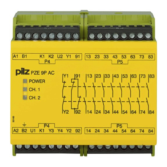
Page 7: Unit Features
Block diagram/terminal configuration Type: 24 V AC/DC : 24 VAC/DC; Order no. 777140, 787140 *Safe separation from non-marked area, except for safety contact 13-14, in accordance with EN 60947-1, 6 kV, basic insulation between all safety contacts. Operating Manual PZE 9P 1003288-EN-13... -
Page 8: Type: 24 - 240 V Ac/Dc
EN 60947-1, 6 kV, basic insulation between all safety contacts. Function description The contact expansion module PZE 9P is an add-on device without delay-on de-energisa- tion. It is used to expand a safety circuit. The contact expansion module is driven by a base unit (e. -
Page 9: Wiring
B1 and B2: The power supply must meet the regulations for extra low voltages with pro- tective electrical separation (SELV, PELV). Preparing for operation Supply voltage 24 - 240 V AC/DC 24 VAC/DC Order no.: 777148, 787148 L1/L+ N/L- Order no.: 777140, 787140 Operating Manual PZE 9P 1003288-EN-13... -
Page 10: Operation
SIL CL 3/PL e at least 1x per month for SIL CL 2/PL d at least 1x per year Operating Manual PZE 9P | 10 1003288-EN-13... -
Page 11: Status Indicators
Open circuit, short circuit or earth fault ( e.g. in the input circuit) Dimensions in mm 75 (2.95") (3.54") 87 (3.42") Operating Manual PZE 9P | 11 1003288-EN-13... -
Page 12: Technical Details
UB AC 10 Ohm 10 Ohm Relay outputs 777140 787140 Number of output contacts Safety contacts (N/O), instant- aneous Auxiliary contacts (N/C) Max. short circuit current IK 1 kA 1 kA Operating Manual PZE 9P | 12 1003288-EN-13... - Page 13 240 V AC G. P. 240 V AC G. P. With current Voltage 24 V DC G. P. Resistive 24 V DC G. P. Resistive With current Pilot Duty B300, R300 B300, R300 Operating Manual PZE 9P | 13 1003288-EN-13...
- Page 14 6,3 A 6,3 A Conv. therm. current with 6 con- tacts 5,8 A 5,8 A Conv. therm. current with 7 con- tacts 5,4 A 5,4 A Conv. therm. current with 8 con- tacts Operating Manual PZE 9P | 14 1003288-EN-13...
- Page 15 93 % r. h. at 40 °C 93 % r. h. at 40 °C Condensation during operation Not permitted Not permitted EN 60947-5-1, EN 61000-6-2, EN EN 60947-5-1, EN 61000-6-2, EN 61326-3-1 61326-3-1 Operating Manual PZE 9P | 15 1003288-EN-13...
- Page 16 Conductor cross section with spring-loaded terminals: Flexible with/without crimp connector – 0,2 - 1,5 mm², 24 - 16 AWG Spring-loaded terminals: Terminal points per connection – Stripping length with spring-loaded terminals – 8 mm Operating Manual PZE 9P | 16 1003288-EN-13...
- Page 17 Residual ripple DC 160 % 160 % Duty cycle 100 % 100 % Inputs 777148 787148 Number Voltage at Input circuit DC 24 V 24 V Current at Input circuit DC 40 mA 40 mA Operating Manual PZE 9P | 17 1003288-EN-13...
- Page 18 500 VA DC1 at 24 V 24 V Min. current 0,01 A 0,01 A Max. current Max. power 50 W 50 W Utilisation category In accordance with the standard EN 60947-5-1 EN 60947-5-1 Operating Manual PZE 9P | 18 1003288-EN-13...
- Page 19 Max. melting integral 240 A²s 240 A²s Blow-out fuse, quick Blow-out fuse, slow Blow-out fuse, gG Circuit breaker 24 V AC/DC, characteristic B/C Contact material AgSnO2 + 0,2 µm Au AgSnO2 + 0,2 µm Au Operating Manual PZE 9P | 19 1003288-EN-13...
- Page 20 30 ms 30 ms With automatic start max. 40 ms 40 ms With automatic start after power on typ. 300 ms 300 ms With automatic start after power on max. 350 ms 350 ms Operating Manual PZE 9P | 20 1003288-EN-13...
- Page 21 Rated impulse withstand voltage 6 kV 6 kV Protection type Housing IP40 IP40 Terminals IP20 IP20 Mounting area (e.g. control cab- inet) IP54 IP54 Mechanical data 777148 787148 Mounting position Mechanical life 10,000,000 cycles 10,000,000 cycles Operating Manual PZE 9P | 21 1003288-EN-13...
- Page 22 8 mm Dimensions Height 87 mm 87 mm Width 90 mm 90 mm Depth 121 mm 121 mm Weight 455 g 455 g Where standards are undated, the 2020-07 latest editions shall apply. Operating Manual PZE 9P | 22 1003288-EN-13...
-
Page 23: Safety Characteristic Data
A safety function's SIL/PL values are not identical to the SIL/PL values of the units that are used and may be different. We recommend that you use the PAScal software tool to calculate the safety function's SIL/PL values. Operating Manual PZE 9P | 23 1003288-EN-13... -
Page 24: Supplementary Data
To increase the service life, sufficient spark suppression must be provided on all output contacts. With capacitive loads, any power surges that occur must be noted. With DC con- tactors, use flywheel diodes for spark suppression. Operating Manual PZE 9P | 24 1003288-EN-13... -
Page 25: Remove Plug-In Terminals
European Parliament and of the Council. The complete EC Declaration of Conformity is available on the Internet at www.pilz.com/downloads. Authorised representative: Norbert Fröhlich, Pilz GmbH & Co. KG, Felix-Wankel-Str. 2, 73760 Ostfildern, Germany Operating Manual PZE 9P... - Page 26 We are represented internationally. Please refer to our homepage www.pilz.com for further details or contact our headquarters. Headquarters: Pilz GmbH & Co. KG, Felix-Wankel-Straße 2, 73760 Ostfildern, Germany Telephone: +49 711 3409-0, Telefax: +49 711 3409-133, E-Mail: info@pilz.com, Internet: www.pilz.com...
Need help?
Do you have a question about the PZE 9P and is the answer not in the manual?
Questions and answers