Table of Contents
Advertisement
Advertisement
Table of Contents

Related Manuals for Pilz PZE 9


Summary of Contents for Pilz PZE 9
- Page 1 PZE 9 Safety relays Operating Manual 1001635-EN-05...
- Page 2 Preface This document is a translation of the original document. All rights to this documentation are reserved by Pilz GmbH & Co. KG. Copies may be made for internal purposes. Suggestions and comments for improving this documentation will be gratefully received.
-
Page 3: Table Of Contents
Type: DC Types: AC Function description Installation Wiring Preparing for operation Operation Status indicators Faults – Interference Dimensions in mm Technical details Safety characteristic data Supplementary data Service life graph Order reference EC declaration of conformity Operating Manual PZE 9 1001635-EN-05... -
Page 4: Introduction
PZE 9 Introduction Validity of documentation This documentation is valid for the product PZE 9. It is valid until new documentation is published. This operating manual explains the function and operation, describes the installation and provides guidelines on how to connect the product. -
Page 5: Safety
Safety Intended use The contact expansion module PZE 9 meets the requirements of EN 60947-5-1, EN 60204-1 and VDE 0113-1. It is used to increase the number of contacts available on a base unit. Base units are all Safety relays with feedback loop Programmable safety systems with feedback loop The category that can be achieved in accordance with EN ISO 13849-1 depends on the... -
Page 6: Use Of Qualified Personnel
Note for overvoltage category III: If voltages higher than low voltage (>50 VAC or >120 VDC) are present on the unit, connected control elements and sensors must have a rated insulation voltage of at least 250 V. Operating Manual PZE 9 1001635-EN-05... -
Page 7: Unit Features
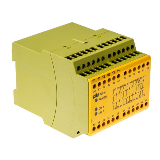
The output relays de-energise and the safety contacts open. Block diagram/terminal configuration Type: DC : 24 DC; Order no. 774150 *Insulation between the non-marked area and the relay contacts: Basic insulation (over- voltage category III), Protective separation (overvoltage category II) Operating Manual PZE 9 1001635-EN-05... -
Page 8: Types: Ac
(overvoltage category III), protective separation (overvoltage category II) Function description The contact expansion module PZE 9 is an add-on device without delay-on de-energisa- tion. It is used to expand a safety circuit. The contact expansion module is driven by a base unit (e. -
Page 9: Installation
The power supply must comply with the regulations for extra low voltages with protect- ive electrical separation (SELV, PELV) in accordance with VDE 0100, Part 410. Ensure the EMC requirements of IEC 60204-1 are met. Operating Manual PZE 9 1001635-EN-05... -
Page 10: Preparing For Operation
The safety function should be checked after initial commissioning and each time the plant/machine is changed. The safety functions may only be checked by qualified personnel. Status indicators LEDs indicate the status and errors during operation: LED on POWER Supply voltage is present. Operating Manual PZE 9 1001635-EN-05... -
Page 11: Faults - Interference
Open circuit, short circuit or earth fault ( e.g. in the input circuit) Dimensions in mm 75 (2.95") 90 (3.54") 87 (3.42") Operating Manual PZE 9 1001635-EN-05... -
Page 12: Technical Details
Number of output con- tacts Safety contacts (N/O), instantaneous Auxiliary contacts (N/C) 1 Max. short circuit current 1 kA 1 kA 1 kA Utilisation category In accordance with the standard EN 60947-4-1 EN 60947-4-1 EN 60947-4-1 Operating Manual PZE 9 1001635-EN-05... - Page 13 240 V AC G. P. With current Voltage 24 V DC G. P. Resistive 24 V DC G. P. Resistive 24 V DC G. P. Resistive With current Pilot Duty B300, R300 B300, R300 B300, R300 Operating Manual PZE 9 1001635-EN-05...
- Page 14 Conv. therm. current with 6 contacts 5,2 A 5,2 A 5,2 A Conv. therm. current with 7 contacts 4,8 A 4,8 A 4,8 A Conv. therm. current with 8 contacts 4,5 A 4,5 A 4,5 A Operating Manual PZE 9 1001635-EN-05...
- Page 15 93 % r. h. at 40 °C Condensation during op- eration Not permitted Not permitted Not permitted EN 60947-5-1, EN EN 60947-5-1, EN EN 60947-5-1, EN 61000-6-2, EN 61326-3-1 61000-6-2, EN 61326-3-1 61000-6-2, EN 61326-3-1 Operating Manual PZE 9 1001635-EN-05...
- Page 16 TWIN crimp 0,2 - 2,5 mm², 24 - 14 0,2 - 2,5 mm², 24 - 14 0,2 - 2,5 mm², 24 - 14 connectors Torque setting with screw terminals 0,6 Nm 0,6 Nm 0,6 Nm Operating Manual PZE 9 1001635-EN-05...
- Page 17 Duty cycle 100 % 100 % 100 % Inputs 774143 774148 774150 Number Voltage at Input circuit DC 24 V 24 V 24 V Current at Input circuit DC 40 mA 40 mA 40 mA Operating Manual PZE 9 1001635-EN-05...
- Page 18 Max. current Max. power 2000 VA 2000 VA 2000 VA DC1 at 24 V 24 V 24 V Min. current 0,01 A 0,01 A 0,01 A Max. current Max. power 200 W 200 W 200 W Operating Manual PZE 9 1001635-EN-05...
- Page 19 Max. melting integral 240 A²s 240 A²s 240 A²s Blow-out fuse, quick 10 A 10 A 10 A Blow-out fuse, slow Blow-out fuse, gG 10 A 10 A 10 A Circuit breaker 24V AC/DC, characteristic Operating Manual PZE 9 1001635-EN-05...
- Page 20 5 contacts – – 6,3 A Conv. therm. current with 6 contacts – – 5,8 A Conv. therm. current with 7 contacts – – 5,4 A Conv. therm. current with 8 contacts – – Operating Manual PZE 9 1001635-EN-05...
- Page 21 With automatic start max. 40 ms 40 ms 40 ms With automatic start after power on typ. 50 ms 50 ms 30 ms With automatic start after power on max. 70 ms 70 ms 40 ms Operating Manual PZE 9 1001635-EN-05...
- Page 22 ABS UL 94 V0 ABS UL 94 V0 ABS UL 94 V0 PPO UL 94 V0 PPO UL 94 V0 PPO UL 94 V0 Connection type Screw terminal Screw terminal Screw terminal Mounting type Fixed Fixed Fixed Operating Manual PZE 9 1001635-EN-05...
-
Page 23: Safety Characteristic Data
A safety function's SIL/PL values are not identical to the SIL/PL values of the units that are used and may be different. We recommend that you use the PAScal software tool to calculate the safety function's SIL/PL values. Operating Manual PZE 9 1001635-EN-05... -
Page 24: Supplementary Data
Prever una extinción de chispas suficiente en todos los contactos de salida para prolongar la vida útil. En caso de cargas capacitivas, controlar las puntas de tensión que puedan crearse. Utilizar diodos volantes para la extinción de chispas de contactores DC. Operating Manual PZE 9 1001635-EN-05... -
Page 25: Order Reference
European Parliament and of the Council. The complete EC Declaration of Conformity is available on the Internet at www.pilz.com/downloads. Representative: Norbert Fröhlich, Pilz GmbH & Co. KG, Felix-Wankel-Str. 2, 73760 Ost- fildern, Germany Operating Manual PZE 9... - Page 26 Back cover Support Technical support is available from Pilz round the clock. Americas Australia Scandinavia Brazil +61 3 95446300 +45 74436332 +55 11 97569-2804 Spain Canada Europe +34 938497433 +1 888-315-PILZ (315-7459) Austria Switzerland Mexico +43 1 7986263-0 +41 62 88979-30...
Need help?
Do you have a question about the PZE 9 and is the answer not in the manual?
Questions and answers