Table of Contents
Advertisement
Quick Links
Advertisement
Table of Contents

Related Manuals for Winget 2B1500


Summary of Contents for Winget 2B1500
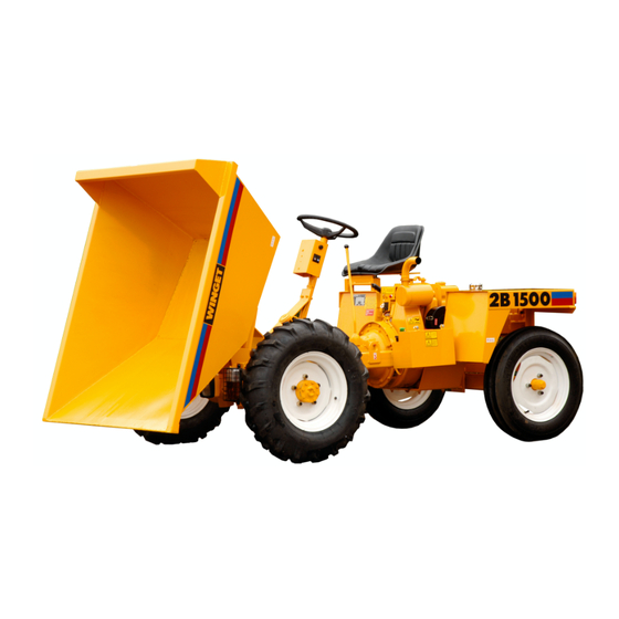
- Page 1 DUMPER 2B1500 HYDRAULIC STEERING OPERATORS HANDBOOK & PARTS From Serial No: 1214 Issued April 2019 WINGET LIMITED, P.O. Box 41, Edgefold Industrial Estate, Plodder Lane, Bolton, BL4 0LR, England Tel: +44 (0) 1204 854650 parts@winget.co.uk service@winget.co.uk www.winget.co.uk...
- Page 3 The contents of this Handbook, although correct at the time of publication, may be subject to alteration by the Manufacturers without prior notice. Winget Limited operate a policy of continuos product development. Therefore, some illustrations or text within this publication may differ from your machine.
-
Page 4: Table Of Contents
Operator’s book template INTRODUCTION CONTENTS Section Page Section Page SERVICE INTRODUCTION Service Safe Working Contents Service schedule chart Introduction to the Handbook Engine TR1 Machine identification Lubrication oil and filter Warranty Terms and Conditions Fuel system Air cleaner SAFE WORKING Gearbox Front axle Machine modification... -
Page 5: Introduction
The contents of this Handbook, although correct at the time of publication may be subject to alteration by the Manufactures without notice. Winget Limited operate a policy of continuous product development. Therefore, some illustrations or text within this publication may differ from your machine. -
Page 6: Warranty Terms And Conditions
No claim will be considered if other than genuine Winget Limited parts, which must be obtained from Winget Limited via an authorised Distributor, are used to effect a repair, or if lubricants other than those recommended by Winget Limited are used. -
Page 7: Safe Working
SAFE WORKING Safety is the responsibility of the persons working with this machine. Think “safety” at all times. Read and remember the contents of this Handbook The safe working recommendations for specific tasks are found with the instructions for the relevant operation in this Handbook. MACHINE MODIFICATION Any modifications to the machine will affect its working parameters and safety factors. - Page 8 SAFE WORKING ALWAYS be aware of local and national regulations governing the use of the machine. NEVER commence work with the machine until the “Daily (or every ten hours)” service checks have been made. (See Service Section for details) ALWAYS check wheel nut tightness daily NEVER carry passengers Ensure that the seat is securely fixed to the machine.
-
Page 9: Skips And Loading
SAFE WORKING SKIPS AND LOADING NEVER exceed the rated payload. The weights of all loads above skip water level must be checked. NEVER remain on the machine when loading the skip with excavators or loaders. Stop the engine, apply the parking brake, dismount, and stand well clear. -
Page 10: Hydraulics
SAFE WORKING NEVER park on a gradient. If this is unavoidable, ALWAYS chock the wheels. NEVER attempt to turn on a gradient. NEVER tow up, down or across a gradient. HYDRAULICS ALWAYS "Dump" residual pressure from the system before leaving the machine or before carrying out any maintenance or adjustments. - Page 11 SAFE WORKING ALWAYS disconnect battery cables and remove battery before using an external charger, carrying out welding repairs or to prevent unauthorised usage when unattended or during a repair. NEVER allow unqualified personnel to attempt to repair, remove or replace any part of the machine, or anyone to remove large or heavy components without adequate lifting tackle.
- Page 12 SAFE WORKING DECALS Attached to the dumper are several pictorial warning decals Ensure that all warning decals fitted to the mixer are legible. If any should become detached, they must be replaced immediately. For detailed information on how to safely use the items described by the decals, see the "Safe working, Operation and Servicing"...
- Page 13 SAFE WORKING This decal indicates the maximum loads that the dumper towbar can carry and pull. These surfaces may be hot. Forks and buckets are not to be used to When loaded, always REVERSE down push or lift the dumper. gradients.
- Page 14 SAFE WORKING...
-
Page 15: Operation
OPERATION CONTROLS AND SERVICE POINTS 1 Steering wheel 8 Skip control, tip/return (Hydraulic tipping) 2 Brake 9 Hydraulic oil filler cap 3 Accelerator 10 Fuel filler cap 4 Clutch 11 Skip release lever (Manual tipping) 5 Seat 12 Gear lever 6 Brake oil reservoir 13 Battery 7 Parking brake... - Page 16 OPERATION ELECTRICAL CONTROLS 20 Key start switch, (electric starting only) 21 Warning light: battery charging (electric starting only) 22 Switch: direction indicators 23 Warning light: direction indicators 24 Switch: hazard warning lights 25 Switch: side and head lights 27 Horn...
-
Page 17: Running-In A New Engine
OPERATION DRIVING THE DUMPER DRIVING THE DUMPER DRIVING THE DUMPER Running-in a new engine Safety warnings While a gradual 'running-in' of a new Read also the "Safe Working" Section engine necessary, before operating the dumper. EXTREMELY IMPORTANT that following instructions should be followed very closely during the first fifty hours of ALWAYS wear correctly fitting operation. -
Page 18: Lister-Petter Tr 1 Engine
OPERATION DRIVING THE DUMPER Lister Petter TR1 engines Description A Dipstick B Lubricating oil filler C Engine control D Decompressor levers E Fuel tank F Cold start oil cups Automatic Exess Fuel Device The engine is fitted with an automatic excess fuel device... - Page 19 OPERATION DRIVING THE DUMPER Hand starting TR1 engines Ensure the parking brake is in the raised "ON" position. Ensure gear lever is in the neutral position. Always use the correct starting handle which has been designed for the engine. Ensure there are no burrs on the handle. Before attempting to use the handle, clean and lightly oil that part of it which fits onto the engine.
- Page 20 OPERATION OPERATION DRIVING THE DUMPER DRIVING THE DUMPER Key Starting TR1 engines Ensure the parking brake is in the raised "ON" position. Ensure the gear lever is in the neutral position. Fully depress and hold down both clutch and accelerator pedals. Check that the decompressor lever, (if fitted) is away (N) from the flywheel.
-
Page 21: Engaging The Gear Lever
OPERATION DRIVING THE DUMPER Gradients Stopping the dumper IMPORTANT: Read the notes in "Safe IMPORTANT: Never make unnecessary 'crash' stops when Working" also remember the travelling at speed, especially in following: forward direction. Slippery or loose surface conditions Release accelerator and brake to a can adversely affect safe machine halt progressively. -
Page 22: Skip Operation
OPERATION DRIVING THE DUMPER Skip operation Skip Operation & Steering Loading Do not attempt to steer the dumper at the Never remain on the dumper when same time as operating the skip. using excavators or loaders to load the skip. Stop the engine, apply the The hydraulic system does not provide parking brake, dismount, and stand well priority flow to the steering system,... -
Page 23: Towing With The Dumper
OPERATION DRIVING THE DUMPER Towing with the dumper Dumpers are not designed as towing vehicles, however, trailers may be towed providing that: 1 The combined weight of the trailer and load does exceed specified maximum dumper drawbar pull and dumper drawbar load (see specifications"). -
Page 24: Service Safe Working
SERVICE SAFE WORKING Read the safety notes in "Safe Working", Section 1 of this book. Also note the following: Safe handling of oils, filters and filter elements Do not allow oils to come into regular contact with skin. This can lead to serious skin diseases. -
Page 25: Air Cleaner
SERVICE SERVICE SERVICE SCHEDULE IMPORTANT: The engine will require additional services or adjustments in addition to those listed below (See the appropriate Engine Operator's handbook or Workshop Manual). Warning lights and indicators REQUIRE IMMEDIATE ACTION SERVICE OPERATION REFERENCE PAGE Every 10 operating hours, or daily, the above and the following Engine oil level Engine... -
Page 26: Gearbox
SERVICE SERVICE SERVICE SCHEDULE SERVICE OPERATION REFERENCE PAGE Every 125 operating hours, the above and the following Air cleaner element Engine Every 250 operating hours, the above and the following Engine oil & filter Engine Fuel filter Engine Every 500 operating hours, the above and the following Air cleaner element Engine... - Page 27 SERVICE ENGINE Lister-Petter TR1 The engine will require additional services and adjustments in addition to those quoted in this handbook. Please refer also to the relevant Engine Operator's Handbook or Workshop Manual. Engine lubrication oil Every 10 operating hours, or daily For engine oil grades and oil change periods when operating in temperatures...
- Page 28 SERVICE ENGINE Stop the engine, allow the oil to settle for 2 minutes. then check the Every 250 hours level on the dipstick (B). Add more oil if necessary. Oil filter For correct grade of engine oil, see Change oil filter element as follows: "Specifications".
- Page 29 SERVICE ENGINE Every 250 Hours Fuel filter Change the fuel filter element if the fuel Being used is not perfectly clean (see below) Every 500 Hours Fuel filter Change fuel filter element as follows:- Disconnect the fuel pipe from below the tank. Remove retaining plug ( R ).
- Page 30 SERVICE ENGINE Every 10 operating hours, or daily Every 10 operating hours, or daily Fuel tank Air cleaner: check/clean/replace Fill the fuel tank at the end of each day to reduce overnight condensation within the Check clean replace tank. element (X) under very dusty conditions. Access the element by unclipping the Never metal cover.
- Page 31 SERVICE ENGINE Every 1000 operating hours Safe handling of oils Change gearbox oil Do not allow oils to come Clean the areas surrounding the dipstick into regular contact with (V) and drain plugs (X). skin. This can lead to Place a suitable container beneath the serious skin diseases.
-
Page 32: Front Axle
SERVICE FRONT AXLE Every 10 operating hours, or daily Check for leaks Check for oil leaks around joints and seals. Every 50 operating hours, or weekly Tighten securing nuts Tighten axle arm/main case joint securing nuts and half shaft nuts. Axle oil level Do not check the oil level until the machine has stood for 2 minutes. -
Page 33: Wheels And Tyres
3.10 SERVICE WHEELS & TYRES Every 10 operating hours, or daily Wheel nuts Tighten wheel nuts whenever necessary, every ten hours or daily. After a wheel change, the nuts should be checked several times a day until they maintain their correct setting. For wheel nut tightening torque, see "Specifications". -
Page 34: Battery
SERVICE 3.11 BATTERY Every 50 hours Safe handling of batteries Check battery electrolyte level The battery contains a The battery is situated beneath a cover sulphuric acid electrolyte on the left-hand side of the dumper. which can cause severe Ensure that the electrical connections burns and produce are clean and tight, and coat the explosive gases. -
Page 35: Steering Valve
3.12 SERVICE SERVICE 3.12 STEERING VALVE Every 50 operating hours, or weekly Steering Valve Retention Check the screws retaining the steering valve and bracket, ensuring they are tight. Check the valve for signs of leaks or damaged hoses. -
Page 36: Greasing
SERVICE 3.13 GREASING Every 50 operating hours, or weekly Always use lubricants of the Location of grease points grade specified. A Tipping rams (2 on each ram) Always lubricate and service B Skip pivots (2) BEFORE work commences, and WITHIN the periods C Propeller shaft (3) specified. -
Page 37: Hydraulic System
3.14 SERVICE HYDRAULIC SYSTEM Description of hydraulic system Hydraulic System Safety The hydraulic system provides power for (see also "Safe Working" section) skip tipping and the power steering. Do not allow oils to come into The main components consist of: regular contact with... - Page 38 SERVICE 3.15...
- Page 39 3.16 SERVICE HYDRAULIC SYSTEM HYDRAULIC SYSTEM Every 10 operating hours, or daily Check hydraulic oil level Hydraulic System Checks Do not check oil level before closing the If the hydraulic system fails to operate tipping rams, and the engine has been completely, or does so extremely slowly, stopped for 2 minutes.
- Page 40 3.17 SERVICE HYDRAULIC SYSTEM First 100 operating hours Every 1000 operating hours Clean / change hydraulic oil filter Clean / change hydraulic oil filter Before cleaning filter, stop the Clean or change the hydraulic oil filter, engine and dump hydraulic using the procedure described in the pressure.
-
Page 41: Technical Information
Operator’s book template TECHNICAL INFORMATION DIMENSIONS Earth skip ft in 2.85 9’ 4" Overall length Overall width 1.64 5’ 5” Overall height 1.37 4’ 6” Skip discharge height 0.130 0’ 5” Skip loading height 1.17 3’ 10” Ground clearance 0.28 0’... -
Page 42: Specifications
TECHNICAL INFORMATION SPECIFICATIONS ENGINE Lister-Petter TR1: Single cylinder, direct injection, naturally aspirated, flywheel fan air cooled diesel. Rotation: Anti-clockwise when looking on the flywheel. TR1: Power output: 6.7 kW (9.0) bhp) @ 1800 ev/min. ELECTRICS (Where fitted) 12 volt negative earth. FUEL System: Single element fuel pumps. -
Page 43: Road Speeds
TECHNICAL INFORMATION SPECIFICATIONS ROAD SPEEDS with engine at 1800 rev/min 1st Gear 2nd Gear 3rd Gear Reverse km/h (mph) km/h (mph) km/h (mph) km/h (mph) (2.6) (5.75) 15.7 (9.8) (2.6) LUBRICANTS AND FLUIDS Total oils (factory fill) Capacities Engine Lub. Oil Rubia H 10W/40 2.7 litres Note: For engine oils used in temperatures above 30 deg. -
Page 44: Main Electrical Circuit
TECHNICAL INFORMATION MAIN ELECTRICAL CIRCUIT (without road lights) TECHNICAL INFORMATION... -
Page 45: Road Lights Electrical Circuit
TECHNICAL INFORMATION ROAD LIGHTS ELECTRICAL CIRCUIT... - Page 47 2B1500 DUMPERS PARTS...
- Page 49 Contents CHASSIS & SKIPS AXLES & STEERING TRANSMISSIONS BRAKES ENGINES ELECTRICS HYDRAULICS DECALS &TOOLS...
- Page 51 2B1500 DUMPER...
- Page 53 Chassis, Panels & Skips A - 1 CHASSIS A - 1B BATTERY TRAY A - 1D SEAT "KAB" (To ISO 6683) A - 1E R.O.P.S. FRAME SKIPS A - 2 Gravity tip A - 3 Hydraulic tip...
- Page 54 A - 1 2B1500 Dumper...
- Page 55 A - 1 CHASSIS & FITTINGS Item Part no Serial no Description 1 40286A01 CHASSIS 2 20355A04 BRACKET, starting handle support 3 11S04E SCREW 4 267S06 WASHER, flat 5 17S05 WASHER, spring 6 7S04 7 11S04E SCREW, set 8 10519A01 SPRING, seat mounting 9 V2004220 WASHER, special...
- Page 56 A - 1B 2B1500 Dumper...
- Page 57 A - 1B BATTERY TRAY Item Part no Serial no Description 10 513358600 COVER, battery 11 V2004055 CLAMP, battery 12 11S04C SCREW,set 13 7S04 14 17S05 WASHER, spring 15 267S06 WASHER, flat 16 61S02 17 267S04 WASHER, flat 18 V2004120 ROD, clamp 19 513358500 TRAY, battery.
- Page 58 A - 1D 2B1500 Dumper...
- Page 59 A - 1D SEAT, “KAB P2N”, with "XH2" suspension unit Item Part no Serial no Description This seat and belt must be used with R.O.P.S. kits (see pages A-1E and A-1F) 1 V2005013 SEAT, assembly c/w with seat belt 2 V2000954 SEAT, 'KAB P2N' 3 V602750 BRACKET, anchorage...
- Page 60 A - 1E 2B1500 Dumper...
- Page 61 A - 1E R.O.P.S. FRAME Item Part no Serial no Description …… V602747 # R.O.P.S. KIT, includes items 1 to 12 below plus KAB XH2/P2N seat assembly with seat belt to ISO 6683. (See page A-1D) 1 V2004946 FRAME, R.O.P.S. 2 11S04G SCREW, set 3 11S04E...
- Page 62 A - 2 2B1500 Dumper...
- Page 63 A - 2 SKIP, gravity tip Item Part no Serial no Description gravity tip SKIP, 1 40295A04 2 10S06 WASHER, flat 3 44S05G PIN, split 4 10892A01 ARM, radius BRACKET, mount, R.H. (illustrated) 5 10893A01 …… BRACKET, mount, L.H. (not illustrated) 10893A02 7 11S05E SCREW, set...
- Page 64 A - 3 2B1500 Dumper DSK-6...
- Page 65 A - 3 SKIP, hydraulic tip Item Part no Serial no Description hydraulic tip SKIP, 1 40295A05 2 10470A10 PIN, pivot, skip 3 11S04C SCREW, set 4 267S06 WASHER, flat 5 59S03 NUT, nylon insert 6 30126A08 BRACKET, pivot, R.H. (illustrated) BRACKET, pivot, L.H.
- Page 67 2B1500 DUMPER...
- Page 69 Axles & Wheels B - 1 WHEELS & TYRES B - 2 DRIVE AXLE, Newage & fittings DRIVE AXLE, Newage, 215 series B - 2A Input pinion & differential B - 2B Planet carrier & axle casing B - 2C Hub &...
- Page 70 B - 1 2B1500 Dumper...
- Page 71 B - 1 WHEELS & TYRES Item Part no Serial no Description Check rim & tyre size before ordering. FRONT 1 24S57 WHEEL, front, L.H., assembly 1 24S58 WHEEL, front, R.H., assembly 2 30192A03 RIM, wheel, 5.5 x 16 3 22S09 TYRE, 7.50 x 16 4 23S03 TUBE, 7.50 x 16...
- Page 72 B - 2 2B1500 Dumper...
- Page 73 B - 2 FRONT DRIVE AXLE ( Newage 215) & FIXINGS Item Part no Serial no Description 2B1500 AXLE, 215 1 30156A13 (See page B-2A for Input pinion & differential) (See page B-2B for planet carrier & axle casing) (See page B-2C for hub & axle shaft)
- Page 74 B - 2A 2B1500 Dumper DAX - 33...
- Page 75 B - 2A INPUT PINION & DIFFERENTIAL Newage 215 series drive axle Item Part no Serial no Description 1 30082A0401 PINION, input cartridge 2 30082A0402 FLANGE, input drive, c/w seal shield 3 30082A0403 PINION, spiral bevel 4 30082A0282 SHIM, 0.25mm ….
- Page 76 B - 2B 2B1500 Dumper V601139 / issue 02 0297...
- Page 77 B - 2B PLANET CARRIER & AXLE CASING Newage 215 series drive axle Item Part no Description Serial no 21 30156A0802 CARRIER, planet 22 30156A0803 GEAR, planet 23 30156A0804 PIN, planet 24 30156A0805 SPACER 25 30082A0265 CIRCLIP 26 30082A0289 BEARING, needle 27 30082A0249 WASHER, thrust 28 30156A0162...
- Page 78 B - 2C 2B1500 Dumper DAX - 41...
- Page 79 B - 2C HUB & AXLE SHAFT Newage 215 series drive axle Item Part no Serial no Description 29 30082A0407 30 30156A0122 STUD, wheel 31 30082A0408 BEARING 32 30082A0409 BEARING 33 30082A0222 SPACER 34 30347A0201 LOCKWASHER 35 30156A0112 DOWEL, spring 36 30082A0410 SEAL, oil 37 8S04B...
- Page 80 B - 2D 2B1500 Dumper DAX - 41...
- Page 81 B - 2D BRAKES Newage 215 series drive axle Item Part no Serial no Description 60 30156A0108 KIT, 'O' ring seals, brake piston *61 30156A0908 DISC, brake, sintered 62 30156A0107 PISTON, brake *63 30156A0909 PLATE, brake, fixed *64 30156A0910 SPACER, brake 65 30082A0419 VALVE, brake bleeding *30156A0911...
- Page 82 B - 3 2B1500 Dumper...
- Page 83 B - 3 STEERING AXLE & STEERING RAM Item Part no Description Serial no 1 V2005330 RAM, steering see page H5 2 V2005342 PIN, retaining 3 267S08 WASHER, flat 4 44S16J PIN, split 5 115S03 BANJO,bolt 5A 100S02 SEAL, bonded 6 114S06D BANJO, body, straight male 7 V2006336...
- Page 84 B - 3 2B1500 Dumper DAX-9A...
- Page 85 B - 3 STEERING AXLE & STEERING RAM Item Part no Serial no Description 35 V602666 BEARING, hub, outer 36 V602668 SEAL, oil, hub bearing 38 V602667 BEARING, hub, inner 39 V602677 STUD, wheel 40 V603755 NUT, slotted, 40mm across flats 42 44S04E PIN, split ISSUE 1 0114...
- Page 87 2B1500 4B2000 DUMPER DUMPERS...
- Page 89 Transmission GEARBOX, Newage C - 1 Used with Newage 215 axle C - 2 FLYWHEEL & CLUTCH C - 3 CLUTCH PEDAL C - 4 PROPELLER SHAFT...
- Page 90 C - 1 2B1500 Dumper...
- Page 91 C - 1 GEARBOX (Used with Newage 215 axles) Item Part no Serial no Description - 30101A04 GEARBOX, (40M2S322), assembly, 1 30101A0201 KNOB, gear lever 2 95S03 NUT, locking 3 20097A05 LEVER, gear 4 30101A0203 CAP, gear lever 5 30101A0204 GAITER, gear lever 6 30101A0205 SPRING, gear lever...
- Page 92 C - 1 2B1500 Dumper...
- Page 93 C - 1 GEARBOX (Used with Newage 215 axles) Item Part no Serial no Description 40 30101A0234 PAD, gear lever 41 28S01C BOLT 42 30101A0235 COVER, top 43 30097A0185 SPRING, detent 44 30097A0199 BALL, detent 45 30101A0237 SHAFT, selector 46 30101A0238 BEARING, needle (part of item 47) 47 30101A0239 SHAFT, primary, assy (with item46)
- Page 94 C - 1 2B1500 Dumper...
- Page 95 C - 1 GEARBOX (Used with Newage 215 axles) Item Part no Serial no Description 83 30218A0203 COUPLING 84 107S03 85 6S01B BOLT 86 66S03A SCREW, set, Imperial, UNC 86 11S04C SCREW, set, Metric 87 41S05 WASHER, spring, Imperial 87 17S05 WASHER, spring, Metric Confirm threads in Engine Adaptor Ring to identify correct set screws 91 67S01...
- Page 96 C - 2 2B1500 Dumper DTR-2B...
- Page 97 C - 2 FLYWHEEL & CLUTCH Item Part no Serial no Description 1 10579A01 BEARING, release 2 28S02D SCREW 3 41S04 WASHER, spring 3A 10531A02 WASHER, locking, 60mm long, Lister-Petter TR1 engines 3B 10531A03 WASHER, locking, 70mm long, Lister-Petter TR1 engines 4 10597A01 COVER 5 10579A0101...
- Page 98 C - 3 2B1500 Dumper DCO-11...
- Page 99 C - 3 CLUTCH PEDAL Item Part no Serial no Description 1 20096A07 PEDAL, clutch 2 10S08 WASHER, flat 3 44S05E PIN, split 4 10481A03 ROD, clutch 5 10S03 WASHER, flat 6 44S03C PIN, split 7 C174J CLEVIS 8 95S03 9 10650A18 PIN, clevis 10 44S02C...
- Page 100 C - 4 2B1500 Dumper...
- Page 101 C - 4 PROPELLER SHAFT Item Part no Serial no Description 1 20088A01 PROPELLER SHAFT ….. 176S01 CAP, grease nipple (not illustrated) 2 6S03C BOLT, gearbox end, 1 1/2“ long 2A 6S03A BOLT, axle end, 1 1/8“ long 3 107S14 NUT, 3/8"...
- Page 103 2B1500 DUMPER...
- Page 105 Brakes D - 1 HANDBRAKE, CABLE & CALIPER D - 2 CALIPER D - 3 BRAKE PEDAL D - 4 BRAKE HOSES & FITTINGS...
- Page 106 D - 1 2B1500 Dumper...
- Page 107 D - 1 HANDBRAKE, (Newage axles only) Item Part no Serial no Description 1 20208A01 LEVER, handbrake assembly 1A 20208A0101 BUTTON, handbrake 1B 20208A0102 SPRING, handbrake 2 11S04C SCREW 3 17S05 WASHER, spring 4 7S04 5 267S06 WASHER, flat 6 10S03 WASHER, flat 7 44S02B PIN, split...
- Page 108 D - 2 2B1500 Dumper DCO-15...
- Page 109 D - 2 CALIPER, parking brake Item Part no Serial no Description ALLOY CALIPERS 1A 10578A01 CALIPER, one pair, assembly 1 11116 SCREW, with hole for pin, item 12 2 28S02P SCREW 3 10578A0101 SPRING, centring TENSION WASHER (obsolete) use item 3 above 6 9S02 7 10578A0104 8 230S01...
- Page 110 D - 3 2B1500 Dumper DCO - 11A...
- Page 111 D - 3 BRAKE PEDAL Item Part no Serial no Description 13 20232A02 PEDAL, brake 14 8S04C BOLT 15 267S06 WASHER, flat 16 17S05 WASHER, spring 17 131S01 NIPPLE, grease, threaded 17A 176S01 CAP, grease nipple 19 C173B SPRING ISSUE 1 0114...
- Page 112 D - 4 2B1500 Dumper...
- Page 113 D - 4 BRAKE HOSES & FITTINGS Item Part no Serial no Description 1 20102A02 MASTER CYL. M10 rod, Girling 1A 10570A01 REPAIR KIT, m/cyl. Girling 2 7S04 NUT, 10mm 3 V2004648 CLEVIS, 10mm 4 10650A18 PIN, clevis 5 10S03 WASHER, flat 6 44S02C PIN, split...
- Page 115 2B1500 DUMPER...
- Page 117 Engine & Controls E - 1 LISTER-PETTER TR1 ENGINE E - 2 ACCELERATOR PEDAL & LINKAGE...
- Page 118 E - 1 2B1500 Dumper...
- Page 119 E - 1 ENGINE, LISTER PETTER TR1 Item Part no Serial no Description 1 V2000759 Engine, TR1, hand start (hydraulic pump drive) 1 V2000760 Engine, TR1, electric start (hydraulic pump drive) 2 20354A03 HANDLE, starting 6 8S05J BOLT 7 267S07 WASHER, flat 8 59S04 NUT, nylon insert...
- Page 120 E - 2 2B1500 Dumper...
- Page 121 E - 2 ACCELERATOR PEDAL & LINKAGE Item Part no Serial no Description 1 20231A03 PEDAL, accelerator 2 8S04C BOLT 3 17S05 WASHER 5 10362A17 6 C160B BALL END 7 2S02 8 41S03 WASHER, spring 9 C173D SPRING, return 10 267S04 WASHER, flat 11 44S02C PIN, split...
- Page 123 2B1500 DUMPER...
- Page 125 Electrics CHARGING & STARTING CIRCUIT F - 1 Lister Petter TR1 electric start engine F - 2 MAIN ELECTRICAL CIRCUIT. F - 3 ROAD LIGHTS. F - 4 CONSOLE, road lights.
- Page 126 F - 1 2B1500 Dumper...
- Page 127 F - 1 CHARGING & STARTING CIRCUIT Lister Petter TR1 electric start engine Item Part no Serial no Description Lister Petter TR1 Engines fitted with ‘Nicsa’ charging system 1 EL36608142 + STATOR, flywheel alternator 1A EL36608143 + ROTOR, flywheel alternator 2 V2004189 SWITCH, key start 9 EL36608144...
- Page 128 F - 2 2B1500 Dumper DEL - 27...
- Page 129 F - 2 MAIN ELECTRICAL CIRCUIT Item Part no Serial no Description 1 109S08 BATTERY 2 10989A06 CABLE, positive 3 V2004204 INSULATOR, battery positive terminal 4 V2004214 ISOLATOR, battery negative terminal 5 V2003510 CABLE, earth 6 20313A06 PANEL, instrument 7 V602634 LIGHT, battery charging 8 V602635 LENS...
- Page 130 F - 3 2B1500 Dumper DEL - 26...
- Page 131 F - 3 ROAD LIGHTS Item Part no Serial no Description 1 10973A03 BRACKET, front lights (hyd. tipping earth skips) 2 11S05F SCREW, set 3 267S07 WASHER, flat 4 17S06 WASHER, spring 5 7S05 6 10973A04 BRACKET, front lights (gravity tip earth skips) 7 11S03E SCREW, set 8 17S04...
- Page 132 F - 3 2B1500 Dumper DEL - 26...
- Page 133 F - 3 ROAD LIGHTS Item Part no Serial no Description 53 ———— BRACKET 54 11S03C SCREW, set 55 17S04 WASHER, spring 56 7S03 60 11S03B SCREW, set (console earth terminal) 61 267S05 WASHER, flat 62 17S04 WASHER, spring 63 7S03 70 V2003651 LIGHT, R.H.
- Page 134 F - 4 2B1500 Dumper DEL - 25...
- Page 135 F - 4 CONSOLE, road lights Item Part no Serial no Description 1 30267A04 CONSOLE 2 20318A01 BACKPLATE, console 3 11S01AA SCREW, set 4 17S02 WASHER, spring 5 7S01 6 153S05 CLAMP, (discard bracket) assembly 7 7S03 8 17S04 WASHER, spring 11 V2003644 SWITCH, lights 12 V2003646...
- Page 137 2B1500 DUMPER...
- Page 139 Hydraulics H - 1 HYD PUMP, TANK & STEER VALVE, HYD TIP H - 1A HYD PUMP, TANK & STEER VALVE, GRA TIP H - 1AA DIRECT DRIVE HYDRAULIC PUMP H - 2 SKIP TIPPING HYDRAULIC CIRCUIT H - 3 CONTROL VALVE.
- Page 140 H - 1 2B1500 Dumper...
- Page 141 H - 1 HYDRAULIC PUMP, TANK & STEER VALVE, HYD TIP Item Part no Serial no Description TANK, hydraulic 1 30286A08 2 11S04C SCREW 3 17S05 WASHER 4 7S04 5 901S02 /1232 FILTER, suction 5A V2005355 1233/ FILTER, suction 5B V2005356 1233/ GASKET 5C V2006399...
- Page 142 H - 1A 2B1500 Dumper DHY - 47...
- Page 143 H - 1A HYDRAULIC PUMP, TANK & STEER VALVE GRAVITY TIP Item Part no Serial no Description TANK, hydraulic 1 30286A08 2 11S04C SCREW 3 17S05 WASHER 4 7S04 5 901S02 /1232 FILTER 5A V2005355 1233/ FILTER, suction 5B V2005356 1233/ GASKET 5C V2006399...
- Page 144 H - 1A 2B1500 Dumper DHY - 47...
- Page 145 H - 1A HYDRAULIC PUMP, TANK & STEER VALVE GRAVITY TIP Item Part no Serial no Description Item 50 refer to TR Engine Parts Manual 50 —- STUD 51 17S05 WASHER, spring 52 7S03 53 8S03C BOLT 54 17S05 WASHER, spring ISSUE 2 0518...
- Page 146 H - 1AA 2B1500 Dumper...
- Page 147 H - 1AA DIRECT DRIVE HYDRAULIC PUMP Item Part no Serial no Description 1 V2006390 STUD 2 V2006381 EXTENSION SHAFT, pump drive 3 417732500 SEAL, oil 4 10977A06 HYDRAULIC PUMP A/C, assembly 5 8S02C BOLT 6 267S04 WASHER, flat 7 17S03 WASHER, spring 8 7S02 10 V2006385...
- Page 148 H - 2 2B1500 Dumper...
- Page 149 H - 2 SKIP TIPPING HYDRAULIC CIRCUIT Item Part no Serial no Description 1 30287A06 RAM (see page H-4) 2 31S02GG HOSE 3 10464A02 FITTING, double tee bracket 4 7S03 4A 17S04 WASHER, spring 5 11S03E SCREW, set 6 31S02YY HOSE 10 176S01 CAP, grease nipple...
- Page 150 H - 3 2B1500 Dumper...
- Page 151 H - 3 CONTROL VALVE, Item Part no Serial no Description 1 V2004106 VALVE, control, assembly 2 V602630 LEVER, knob & nut, assembly 3 7S04 4 V602629 KIT, control valve repair 5 V603565 END CAP, lever 6 V603605 VALVE, relief 7 V603606 END CAP, spring base 10 100S03...
- Page 152 H - 4 2B1500 Dumper...
- Page 153 H - 4 RAM, (METRIC) tipping, hydraulic skip Item Part no Serial no Description 1A 30287A06 RAM, hyd, assembly, metric rod & cy 1 30287A0601 CYLINDER, ram (metric) 2 30287A0602 ROD, piston (metric) 3 30287A0603 NUT, gland ring 4 30287A0604 PISTON, one piece 5 30287A0605 Spacer, rod, not illustrated...
- Page 154 H - 5 2B1500 Dumper...
- Page 155 H - 5 RAM, steering Item Part no Serial no Description 1 V2005330 RAM, assembly steering 2 V603576 RETAINER, cylinder 3 V603577 CYLINDER 4 V603578 5 V603579 SCREW, grub 6 V603580 PISTON 7 V603013 BUSH 10 V603574 KIT, seals ISSUE 1 0114...
- Page 156 H - 6 2B1500 Dumper...
- Page 157 H - 6 STEER COLUMN & VALVE Item Part no Serial no Description 2 V2002872 COLUMN, steering 4 17S08 WASHER, spring 4A 267S09 WASHER, flat 5 V2004152 WHEEL, steering c/w spinner 6 68S05C SCREW, socket cap 7 8S04C BOLT 8 17S05 WASHER, spring 9 CSE182 SPACER...
- Page 159 2B1500 4B2000 DUMPER DUMPERS...
- Page 161 Miscellaneous J - 1 to J - 3 DECALS & PLATES...
- Page 162 J - 1 2B1500 Dumper...
- Page 163 J - 1 DECALS & PLATES Item Part no Serial no Description — V601779 KIT, decals, 2B1500 1 kit Each kit contains all decals required for one dumper 1 V2003100 DECAL, Hydraulic oil 2 V2003101 DECAL, Diesel fuel 3 V2003038...
- Page 164 J - 2 2B1500 Dumper...
- Page 165 J - 2 DECALS & PLATES Item Part no Serial no Description 1 V2003153 DECAL, 2B1500 3 DM197 DECAL, Lubrication oils 7 V2003142 DECAL, Warning - wheel nuts 9 10540A02 DECAL, 35psi tyre pressure 15 10848A01 DECAL, Brake fluid 17 V2004472 DECAL, Max.
- Page 166 J - 3 2B1500 Dumper...
- Page 167 J - 3 DECALS & PLATES Item Part no Serial no Description 1 V2004227 DECAL, Battery isolator 2 V2004229 DECAL, Operators handbook 3 V2004245 DECAL, No buckets, No forks 4 V2004244 DECAL, Towbar loadings 5 V2004282 DECAL, Hot surfaces 6 V2004307 DECAL, Electrical hazard 7 V2004288 DECAL, Starting handle...
- Page 169 CALIFORNIA CALIFORNIA CALIFORNIA CALIFORNIA Proposition 65 Warning Diesel engine exhaust and some of its constituents are known to the State of California to cause cancer, birth defects, and other reproductive harm...
Need help?
Do you have a question about the 2B1500 and is the answer not in the manual?
Questions and answers