Table of Contents
Advertisement
Advertisement
Table of Contents

Subscribe to Our Youtube Channel
Related Manuals for Winget 4B2000


Summary of Contents for Winget 4B2000
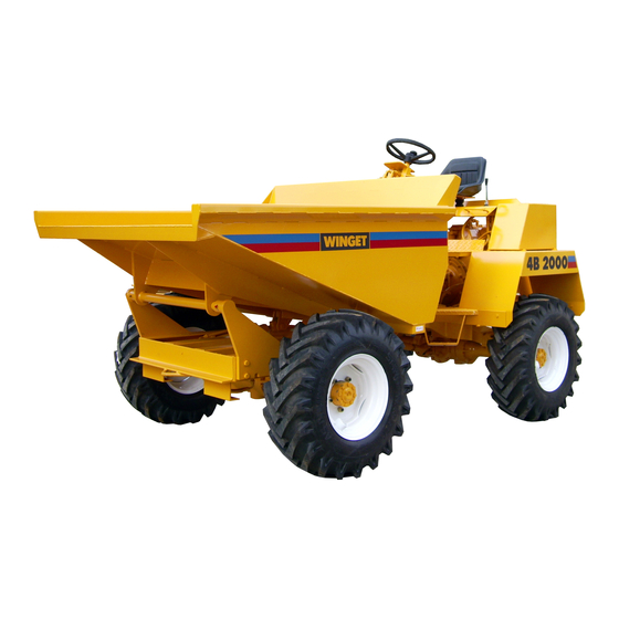
- Page 1 DUMPER 4B2000 OPERATORS HANDBOOK Manual MANS524 March 2013 WINGET LIMITED, P.O. Box 41, Edgefold Industrial Estate, Plodder Lane, Bolton, BL4 0LR, England Tel: +44 (0) 1204 854650 Fax: +44 (0) 1204 854663 E mail: parts@winget.co.uk, service@winget.co.uk www.winget.co.uk...
- Page 2 The contents of this Handbook, although correct at the time of publication, may be subject to alteration by the Manufacturers without notice. Winget Limited operate a policy of continuous product development. Therefore, some illustrations or text within this publication may differ from your machine.
- Page 3 INTRODUCTION CONTENTS Section Page Section Page INTRODUCTION SERVICE Contents Safe working Introduction to the Handbook Service schedule chart Machine identification Engine Warranty Terms & Conditions Fuel System Air Cleaner Gearbox 3.10 Transfer box 3.11 SAFE WORKING Propeller shafts 3.12 Machine modification Battery 3.13 Training...
- Page 4 INTRODUCTION THE HANDBOOK WARNING The Operator must read all the Handbook and fully understand its contents before attempting to operate the machine. THE HANDBOOK MUST NOT BE REMOVED FROM THE MACHINE. The Handbook should be kept clean and in good condition. Additional copies of the Handbook can be obtained from your Distributor.
- Page 5 No claim will be considered if other than genuine Winget Limited parts, which must be obtained from Winget Limited via an authorised Distributor, are used to effect a repair, or if lubricants other than those recommended by Winget Limited are used.
-
Page 6: Machine Modification
SAFE WORKING Safety is the responsibility of all persons working with this machine. Think “safety” at all times. Read and remember the contents of this handbook. The safe working recommendations for specific tasks are found with the instructions for the relevant operation in this Handbook. MACHINE MODIFICATION WARNING Any modifications to the machine will affect its working parameters and safety factors. - Page 7 SAFE WORKING ALWAYS be aware of local and national regulations governing the use of the machine. NEVER commence work with the machine until the “Daily (or every ten hours)” service checks have been made. (See Service Section for details) ALWAYS check wheel nut tightness daily. NEVER carry passengers.
-
Page 8: Skips And Loading
SAFE WORKING SKIPS AND LOADING WARNING NEVER exceed the rated payload. The weights of all loads above skip water level must be checked. NEVER remain on the machine when loading the skip with excavators or loaders. Stop the engine, apply the parking brake, dismount, and stand well clear. -
Page 9: Hydraulics
SAFE WORKING HYDRAULICS WARNING ALWAYS “Dump” residual pressure from the system before leaving the machine or before carrying out any maintenance or adjustments. If maintenance work requires the skip to be in the raised position, then it must be raised and supported before dumping the pressure. Dump pressure by switching off the engine, then moving the hydraulic control lever several times in each direction. - Page 10 SAFE WORKING ALWAYS obtain advice before mixing oils; some are incompatible. If in doubt drain and refill. NEVER allow oils and fuels to come into regular contact with skin. This can lead to serious skin diseases including, medical evidence suggests, skin cancer.
- Page 11 SAFE WORKING DECALS Attached to the dumper are several pictorial warning decals Ensure that all decals fitted to the dumper are legible. If any should become detached, they must be replaced immediately For detailed information on how to safely use the items described by the decals, see the “Safe working, Operation and Servicing”...
- Page 12 SAFE WORKING CE (EC machines only) Beware of electrical hazards Always reverse down gradients when These surfaces may be hot. loaded The figures shown on these decals are Forks and buckets are not to be used to the maximum loads for the skips onto push or lift the dumper.
- Page 13 SAFE WORKING...
- Page 14 OPERATION CONTROLS AND SERVICE POINTS 1 Hydraulic oil filler cap 7 Foot Brake 2 Skip control, tip/return 8 Accelerator 3 Clutch 9 Parking brake 4 Gear lever 10 Fuel filler cap 5 Steering wheel 11 Key start switch (where fitted) 6 Seat 12 Engine starting handle (stowage)
- Page 15 OPERATION ROAD LIGHTS SWITCH PANEL 20 Horn 21 Switch: Side and head lights 22 Switch: Hazard warning lights 23 Flasher unit 24 Fuse box 25 Switch: Direction indicators 26 Warning light: Direction indicators...
-
Page 16: Running-In A New Engine
OPERATION DRIVING THE DUMPER Running-in a new engine Safety warnings While a gradual ‘running-in’ of a new Read also the “Safe Working” Section engine necessary, before operating the dumper. EXTREMELY IMPORTANT that following instructions should be followed very closely during the first fifty hours of WARNING ALWAYS wear correctly fitting operation. - Page 17 OPERATION DRIVING THE DUMPER Petter PH2 engines (UP TO 1988) To start Petter PH2 engines: Ensure the parking brake is in the raised “ON” position. Ensure gear lever is in the neutral position. WARNING If a starting handle is to be used, see that the shaft is greased.
- Page 18 OPERATION DRIVING THE DUMPER Lister ST2 engines (UP TO 1988) To hand start Lister ST2 engines: Ensure the parking brake is in the raised “ON” position. Ensure gear lever is in the neutral position. Move decompressor lever over towards the flywheel (F). Pull the control lever outwards and allow it to rotate anticlockwise so that it abuts against the top stop and is in a vertical...
- Page 19 OPERATION DRIVING THE DUMPER To key (Electric) start Lister ST2 engines: Ensure the parking brake is in the raised “ON” position. Ensure gear lever is in the neutral position. Depress and hold down the accelerator. Pull the control lever outwards and allow it to rotate anticlockwise so that it abuts against the top stop and is in a vertical position (G).
- Page 20 OPERATION DRIVING THE DUMPER TS/TR2 engines Description A Dipstick B Lubricating oil filler C Engine control D Decompressor levers F Cold start oil cup G Fuel lift pump Automatic Exess Fuel Device The engine is fitted with an automatic excess fuel device which...
- Page 21 OPERATION DRIVING THE DUMPER Hand starting TS/TR2 engines Ensure the parking brake is in the raised “ON” position. Ensure gear lever is in the neutral position. Always use the correct starting handle which has been designed for the engine. Ensure there are no burrs on the handle. Before attempting to use the handle, clean and lightly oil that part of it which fits onto the engine.
- Page 22 OPERATION DRIVING THE DUMPER Key Starting TS/TR2 engines Ensure the parking brake is in the raised “ON” position. Ensure the gear lever is in the neutral position. Fully depress and hold down both clutch and accelerator pedals. Check that the decompressor lever, (if fitted) is away (N) from the flywheel.
-
Page 23: Gradients
2.10 OPERATION DRIVING THE DUMPER Gradients Stopping the dumper IMPORTANT: Never make unnecessary IMPORTANT: Read the notes in “Safe ‘crash’ stops when travelling at speed, Working” also remember especially in forward direction. following: Slippery or loose surface conditions can Release accelerator and brake to a halt adversely affect safe... -
Page 24: Skip Operation
OPERATION 2.11 DRIVING THE DUMPER Skip operation Rotating skip (hydraulic rotation) Loading The skip is operated by a joystick control Never remain on the dumper when using valve; the lever of which is moved through excavators or loaders to load the skip. a gate. -
Page 25: Towing
2.12 OPERATION DRIVING THE DUMPER Towing with the dumper Dumpers are not designed as towing vehicles, however, trailers may be towed providing that: 1 The combined weight of the trailer and its load does not exceed the specified maximum dumper payload. (see"specifications") 2 Trailers may be towed in first gear on level dry ground, provided a purpose... - Page 26 SERVICE SAFE WORKING WARNING Read the safety notes in “Safe Working”, Section 1 of this book. Also note the following: Safe handling of oils, filters and filter elements WARNING Do not allow oils to come into regular contact with skin. This can lead to serious skin diseases.
- Page 27 SERVICE SERVICE SCHEDULE IMPORTANT: The engine will require additional services or adjustments in addition to those listed below (See the appropriate Engine Operator’s handbook or Workshop Manual). Warning lights and indicators WARNING REQUIRE IMMEDIATE ACTION. SERVICE OPERATION REFERENCE PAGE Every 10 operating hours, or daily, the above and the following Engine oil level Engine...
- Page 28 SERVICE SERVICE SCHEDULE SERVICE OPERATION REFERENCE PAGE Every 125 operating hours, the above and the following Air cleaner element Engine Every 250 operating hours, the above and the following Engine oil and filter Engine Fuel filter Engine Every 300 operating hours, the above and the following Hydraulic oil filter Hydraulic system...
-
Page 29: Engine
SERVICE ENGINE IMPORTANT Engines fitted in dumpers To service the following engines, Lister ST2 and Petter PH2 Up to 1985: Lister ST2 Petter PH2 1985 to 1989: Lister-Petter PH2 Please refer to relevent Engine Operator’s Handbook or Workshop Manual. 1985 to 1989: Lister-Petter TS2 Note: from 1989 the TS2 has been offered as an Lister-Petter TS/TR2 option... - Page 30 SERVICE ENGINE Every 250 hours Engine oil Drain and refill the oil sump as follows: If possible run the engine immediately before draining the oil. Place a suitable container under the drain plug. Remove the drain plug (D) and drain oil. Clean and coat the threads of the drain plug with an appropriate sealant.
- Page 31 SERVICE ENGINE Every 10 operating hours, or daily Fuel tank Fill the fuel tank at the end of each day to reduce overnight condensation within the tank. WARNING Never mix gasoline or any other fuel mixes with diesel fuel because of increased fire or explosion risks.
- Page 32 SERVICE ENGINE Every 250 hours Fuel filter element/cartridge Change the fuel filter element/cartridge if the fuel being used is not perfectly clean (see below). Every 500 hours Filter Element, or Cartridge Agglomerator Change Fuel Filter Element as follows: Remove the retaining bolt (E).
-
Page 33: Fuel System
SERVICE ENGINE Priming the fuel system Prime the system as follows: Fill the fuel tank Move the engine control lever to the RUN position. Release the bleed screw (O) on the filter head, then operate the priming lever (P) on the lift pump until a full air free flow is obtained Retighten bleed screw (O) Vent each injector pump in turn by... -
Page 34: Air Cleaner
SERVICE ENGINE Every 10 operating hours, or daily Air cleaner: clean/replace Clean or replace the outer element (A) under very dusty conditions as described below: Every 125 operating hours Air cleaner: clean/replace Clean or replace the outer element (A) under moderately dusty conditions as described below: Access the elements by unhooking the retaining clips and removing the cover. -
Page 35: Gearbox
3.10 SERVICE GEARBOX Safe handling of oils Every 1000 operating hours WARNING Do not allow oils to come into Change gearbox oil regular contact with skin. This Clean the areas surrounding the dipstick can lead to serious skin (V) and drain plugs (X). diseases. -
Page 36: Transfer Box
SERVICE 3.11 TRANSFER BOX Every 50 operating hours, or weekly Check transfer gearbox oil level Clean the area surrounding the filler/level plug (Y) before removing it. Check and top-up through the filler/level plug hole (Y) until the oil is level with the bottom of that hole. -
Page 37: Propeller Shafts
3.12 SERVICE PROPELLER SHAFT Propeller shaft Installation ALWAYS ensure that the larger yoke (X) of the propeller shaft is fitted to the transfer box, NOT the smaller yoke (Y). -
Page 38: Battery
SERVICE 3.13 BATTERY Safe handling of batteries Every 50 hours WARNING The battery contains a Check battery electrolyte level sulphuric acid electrolyte The battery is situated beneath a cover which can cause severe burns on the left-hand side of the dumper. and produce explosive gases. -
Page 39: Hydraulic System
It is illegal to dispose of waste oil into drains or water Note: Hydraulically rotated skips courses or to bury it. Hydraulically rotated skips on the 4B2000 utilise a load sensing steer valve and a separate priority valve. Dumping hydraulic pressure... - Page 40 SERVICE 3.14A HYDRAULIC SYSTEM Dumpers with hydraulically rotated skips The tank, filter, pump and steering circuit operate in basically the same manner as for the conventional forward tipping skip. (see the previous and following pages), with the addition of a load sensing steer valve and a separate flow priority valve.
- Page 41 SERVICE 3.15 HYDRAULIC SYSTEM...
- Page 42 3.16 SERVICE HYDRAULIC SYSTEM Hydraulic System Checks Every 10 operating hours, or daily If the hydraulic system fails to operate completely, or does so extremely slowly, Check hydraulic oil level carry out the following procedures. Do not check oil level before closing Check that the hydraulic tank is full of oil the tipping rams, and the engine has to the correct level.
- Page 43 SERVICE 3.17 HYDRAULIC SYSTEM Provided that the oil does not become Every 300 operating hours contaminated it can be used to refill the Change filter element tank after the strainer has been cleaned and replaced. Change the filter element, using the Wash the strainer in white spirit and procedure described in the previous “First check it for any damage.
- Page 44 3.18 SERVICE HYDRAULIC SYSTEM Every 1000 operating hours Change hydraulic oil engine operate hydraulics to warm the oil. Fully close the tipping rams. Switch off the engine and dump hydraulic pressure. Clean the area surrounding the hydraulic tank strainer and filler cap. Place a suitable container on the ground beneath the strainer to catch oil.
-
Page 45: Greasing
SERVICE 3.19 GREASING Every 50 operating hours, or weekly WARNING Always use lubricants of the grade specified. Always lubricate and service BEFORE work commences, and WITHIN the periods specified. Grease points Clean nipples BEFORE and AFTER greasing. Apply the grease gun until clean grease appears. -
Page 46: Braking Systems
3.20 SERVICE BRAKING SYSTEM Salisbury axles Brake System F Lock both bleed screws and top up The service brakes consist of calipers reservoir to the correct level. acting upon dry discs. G Apply normal working load on brake The brake system is designed to require pedal for two or three minutes and minimum maintenance,... - Page 47 SERVICE 3.21 BRAKING SYSTEM Newage axles Brake System The service brakes consist of totally Note: Always ensure that free play of 1 sealed oil immersed multi-discs fitted to 2 mm exists between the master within the front axle. (The rear axle only cylinder push rod and the piston when has brakes fitted as an option.) the brake pedal is released.
-
Page 48: Wheels & Tyres
3.22 SERVICE WHEELS & TYRES Every 10 operating hours, or daily Wheel nuts Tighten wheel nuts whenever necessary, every ten hours or daily. After a wheel change, the nuts should be checked several times a day until they maintain their correct setting. For wheel nut tightening torque, see “Specifications”. -
Page 49: Axles
SERVICE 3.23 AXLES Every 10 operating hours, or daily Check for leaks Check for oil leaks around joints and seals. Every 50 operating hours, or weekly Tighten securing nuts Tighten axle arm/main case joint securing nuts and half shaft nuts. Axle oil level Do not check the oil level until the machine has stood for 2 minutes. - Page 50 3.24 SERVICE...
- Page 51 TECHNICAL INFORMATION DIMENSIONS Machine Model Earth skip High discharge A Overall height 1.83 m 1.83 m B Skip loading height 1.33 m 1.55 m C Wheel base 1.79 m 1.79 m D Overall length 3.55 m 3.27 m E Ground clearance 0.20 m 0.20 m F Overall width...
-
Page 52: Dimensions
4.1A TECHNICAL INFORMATION DIMENSIONS Manual rotating Hydraulic rotating Machine Model skip skip A Overall height 1.83 m 1.83 m B Skip loading height 1.44 m 1.35 m C Wheel base 1.79 m 2.10 m D Overall length 3.71 m 3.67 m E Ground clearance 0.20 m 0.20 m... -
Page 53: Specifications
TECHNICAL INFORMATION SPECIFICATIONS ENGINES Petter PH2: up to 1985 “See relevent Engine Operator’s handbook”. Lister ST2: “See relevent Engine Operator’s handbook”. Lister-Petter PH2: 1985 to 1989 “See relevent Engine Operator’s handbook”. Lister-Petter TS2 1985 to 1989 Lister-Petter TR2: Twin cylinder, direct injection, naturally aspirated, 1989 to date flywheel fan air cooled diesel. -
Page 54: Adjustments
TECHNICAL INFORMATION SPECIFICATIONS ROAD SPEEDS 1st Gear 2nd Gear 3rd Gear Reverse Km/h (mph) km/h (mph) km/h (mph) km/h (mph) Petter PH2 3.6 (2.2) 8.4 (5.2) 16.1 (10.0) 4.0 (2.5) Lister ST2 and Lister-Petter TS/TR2 4.3 (2.7) 10.0 (6.2) 18.5 (11.5) 4.8 (3.0) LUBRICANTS AND FLUIDS Total oils (factory fill) Capacities... -
Page 55: Machine Weight
TECHNICAL INFORMATION SPECIFICATIONS CAPACITIES SKIP TYPE Standard High discharge Rotating 2000 kg 2000 kg 1630 kg (up to serial no.1092) Payload 2000 kg (from serial no.1093) 850 litres 760 litres 935 litres Water level 1100 litres 800 litres 992 litres Struck 1500 litres 1207 litres... -
Page 56: Electrical Circuit, Without Road Lights
TECHNICAL INFORMATION MAIN ELECTRICAL CIRCUIT (without road lights) Later dumpers with Lister-Petter ‘NISCA’ charging system... - Page 57 TECHNICAL INFORMATION ROAD LIGHTS ELECTRICAL CIRCUIT 4B2000 dumpers from serial number 0863...
- Page 58 4B2000 4B2000 4B2000 4B2000 Contents DUMPERS DUMPERS DUMPERS DUMPERS CHASSIS & SKIPS AXLES & STEERING TRANSMISSIONS BRAKES ENGINES ELECTRICS HYDRAULICS DECALS NUMERICAL INDEX...
- Page 59 Chassis, Panels & Skips CHASSIS A - 1 Non hydraulic rotating skip CHASSIS, front A - 1A Hydraulic rotating skip A - 2 BATTERY CARRIER SKIPS A - 3 Earth & concrete A - 4 Rotating, manually operated A - 4A Rotating, hydraulically operated A - 5 High discharge...
- Page 60 A - 1 4B2000 Dumper...
- Page 61 A - 1 CHASSIS Item Part no Serial no Description CHASSIS, front (to fit Salisbury axle) 1 40100A33 1 40100A32 CHASSIS, front (to fit Newage axle) 2 40101A05 CHASSIS, rear (to fit Salisbury axle) 2 40101A06 CHASSIS, rear (to fit Newage axle) 5 10375A07 BOLT 6 10609A02...
- Page 62 A - 1A 4B2000 Dumper...
- Page 63 A - 1A CHASSIS, Hydraulic rotating skip Item Part no Serial no Description 1 V2004770 CHASSIS, front, rotating skip 2 10640A03 RING, bearing 3 11S05E SCREW, set 4 267S07 WASHER, flat 5 61S05 NUT, “Binx”, self-locking 6 54S08J PIN, roll 10 V2004145 FRAME, rotating 11 11S05E...
- Page 64 A - 2 4B2000 Dumper...
- Page 65 A - 2 BATTERY CARRIER Item Part no Serial no Description 5 30080A03 CARRIER, battery 5A 30080A0303 BAR, locking 6 11S04C SCREW, set 7 59S03 NUT, 'Nyloc' self-locking 8 40SA17 TIE BAR 9 9S01 10 267S04 WASHER, flat 11 10559A01 CLAMP, battery 15 10742A05 COVER, battery...
- Page 66 A - 3 4B2000 Dumper...
- Page 67 A - 3 SKIP, earth & concrete Item Part no Serial no Description 1 40089A04 SKIP, concrete, 0.96 m 1 40275A02 SKIP, earth, 0.85 m 2 30126A10 BRACKET, R.H., skip support 2A 30126A11 BRACKET, L.H., skip support 4 8S06G BOLT 5 267S09 WASHER, flat 6 59S11...
- Page 68 A - 4 4B2000 Dumper...
- Page 69 A - 4 SKIP, Manual rotating Item Part no Serial no Description 40312A01 SKIP, 508mm mouth, asembly ..…. ..…. 40312A02 SKIP, 1067mm mouth, asembly 1 40217A01 SKIP, 508mm mouth 1 40217A02 SKIP, 1067mm mouth 2 40116A03 FRAME, skip 2A 131S01 NIPPLE, grease 2B 176S01 CAP, grease nipple...
- Page 70 A - 4A 4B2000 Dumper...
- Page 71 A - 4A SKIP, Hydraulic rotating Item Part no Serial no Description 1 V2004449 SKIP, rotating, hydraulically swivelled 5 10522A04 PIN, skip pivot 6 267S06 WASHER, flat 7 17S05 WASHER, spring 8 7S04 9 11S04C SCREW, set 10 10919A01 PIN, ram pivot 11 267S06 WASHER, flat 12 11S04C...
- Page 72 A - 5 4B2000 Dumper DSK-3...
- Page 73 A - 5 SKIP, high discharge Item Part no Serial no Description 1A 40313A01 SKIP, high discharge, assembly 1 40299A01 SKIP, high discharge 2 40252A02 FRAME 3 10932A01 PIN, skip pivot 3A 131S01 NIPPLE, grease 3B 176S01 CAP, grease nipple 4 11S04C SCREW, set 5 7S04...
- Page 74 A - 6 4B2000 Dumper...
- Page 75 A - 6 PANELS Item Part no Serial no Description 1 30184A02 PLATE, mounting 2 11S04C SCREW, set 3 7S04 4 17S05 WASHER, spring 5 30125A02 SUPPORT, steering column 6 11S04C SCREW, set 7 7S04 8 17S05 WASHER, spring 13 435375 GROMMET 14 40280A11 MUDWING, L.H.
- Page 76 A - 6 4B2000 Dumper...
- Page 77 A - 6 PANELS Item Part no Serial no Description 42 30148A06 FRAME, seat 43 10519A01 SPRING, rubber 44 7S04 44A 206S03C SCREW, counter sunk 45 17S05 WASHER,spring 46 C180B WASHER, flat 47 30025A09 / Jan-88 PLATE, seat support 47 30025A19 Jan-88 / PLATE, seat support 48 11S04C...
- Page 78 A - 10 4B2000 Dumper DCH-67...
- Page 79 A - 10 ROPS frame (Kit) Item Part no Serial no Description Machines with Lister-Petter TS2 & TR2 engines V602753 ROPS KIT, includes items 1 to 15 listed below. ……… Plus…… Seat assembly KAB XH2/P2N to ISO 6683 V2005013 (see page A - 11). TS/TR exhaust silencer kit V602755 (see page E - 3A) Machines with Lister-Petter PH2, P600 &...
- Page 80 A - 11 4B2000 Dumper...
- Page 81 V602754 (see page A - 10) V602755 (see page E - 3A) All 4B2000 dumpers which are fitted with a R.O.P.S. (Roll Over Protective Structure) including 'Export' models must be fitted with this seat assembly. Earlier versions of the KAB seating XL or XH suspension unit do not meet the requirements of the ISO 6683 (Seat Belt Pull Test) and should not be used in conjunction with a R.O.P.S.
- Page 82 Axles WHEELS & TYRES B - 1 STEERING COLUMN B - 2 AXLES, Salisbury Dry disc brakes B - 5 Non braked B - 6 Oil immersed brakes B - 7 AXLES, Newage Axle identification: Up to serial no. 1092 B - 7A Axle identification: From serial no.
- Page 83 B - 1 4B2000 Dumper AX-87...
- Page 84 B - 1 WHEELS & TYRES Item Part no Serial no Description Wheels suitable for all types of axle. - 24S25 WHEEL ASSEMBLY, L.H. - 24S26 WHEEL ASSEMBLY, R.H. 1 30192A03 RIM, 5.5 x 16 2 20S08 TYRE, 7.5 x 16 3 23S03 TUBE, 7.5 x 16 4 10668A01...
- Page 85 B - 2 4B2000 Dumper...
- Page 86 B - 2 STEERING COLUMN Item Part no Serial no Description 2 CSE1781 COLUMN, steering assembly 3 95S06 # NUT (5/8" UNF) # NUT (M16 x 1.5 pitch) …………. Check thread before ordering nut 4 267S09 WASHER, flat 4A 17S08 WASHER, spring 5 40064A01 WHEEL, steering, 400mm dia...
- Page 87 B - 5 4B2000 Dumper...
- Page 88 B - 5 DRIVE AXLE, Salisbury dry disc Item Part no Serial no Description - 30166A01 AXLE, assembly 30166A0101 BEARING 30166A0102 CARRIER & TUBE, assembly 30166A0103 BOLT, diff bearing cap 30166A0104 GEAR & PINION assembly 30166A0105 WASHER 30166A0106 NUT, pinion locking 30166A0107 NUT, drive gear locking 30166A0108...
- Page 89 B - 5 4B2000 Dumper...
- Page 90 B - 5 DRIVE AXLE, Salisbury dry disc Item Part no Serial no Description 30166A0145 WASHER, thrust 30166A0146 GASKET, pinion oil seal 30166A0147 SLINGER, pinion oil 30166A0148 COVER, gear carrier 30166A0149 COVER, gasket 30166A0150 SHIM, inner pinion bearing, 0.003" 30166A0151 SHIM, inner pinion bearing, 0.005"...
- Page 91 B - 6 4B2000 Dumper...
- Page 92 B - 6 DRIVE AXLE, Salisbury non braked Item Part no Serial no Description - 30171A01 AXLE, assembly 1 30166A0101 BEARING 2 30171A0101 CARRIER & TUBE, assembly 3 30166A0103 BOLT, diff bearing cap 4 30166A0104 GEAR, assembly 5 30166A0105 WASHER 6 30166A0106 NUT, pinion locking 7 30166A0107...
- Page 93 B - 6 4B2000 Dumper...
- Page 94 B - 6 DRIVE AXLE, Salisbury non braked Item Part no Serial no Description 44 30166A0144 WASHER, thrust 45 30166A0145 WASHER, thrust 46 30166A0146 GASKET, pinion oil seal 47 30166A0147 SLINGER, pinion oil 48 30166A0148 COVER, gear carrier 49 30166A0149 COVER, gasket 50 30166A0150 SHIM, inner pinion bearing, 0.003"...
- Page 95 B - 7 4B2000 Dumper...
- Page 96 B - 7 DRIVE AXLE, Salisbury oil immersed Item Part no Serial no Description - 30242A01 AXLE, assembly 30242A0101 STUD, nylon patch locking 30242A0102 WASHER, locking 30242A0103 30242A0104 CIRCLIP 30242A0105 WASHER, locking 30242A0106 STUD 30242A0107 BOLT 30242A0108 WASHER, locking 30242A0109 SCREW &...
- Page 97 B - 7 4B2000 Dumper...
- Page 98 B - 7 DRIVE AXLE, Salisbury oil immersed Item Part no Serial no Description 30166A0104 GEAR, assembly 30166A0105 WASHER 30166A0106 NUT, pinion locking 30166A0107 STRAP, ‘L’, drive gear 30166A0108 BOLT, drive gear 30166A0109 PLUG, level/filler 30166A0113 SHIM, diff bearing, 0.028" 30166A0114 SHIM, diff bearing, 0.030"...
- Page 99 B - 7 4B2000 Dumper...
- Page 100 B - 7 DRIVE AXLE, Salisbury oil immersed Item Part no Serial no Description 30166A0146 GASKET, pinion oil seal 30166A0147 SLINGER, oil, pinion 30242A0145 COVER, gear carrier 30166A0149 GASKET, carrier cover 30166A0150 SHIM, pinion bearing inner, 0.003" 30166A0151 SHIM, pinion bearing inner, 0.005" 30166A0152 SHIM, pinion bearing inner, 0.010"...
- Page 101 B - 7A 4B2000 Dumper...
- Page 102 B - 7A NEWAGE AXLES & fixings Up to serial no. 1092 Item Part no Serial no Description 1 ————— / 1092 AXLE, type 200RF, with brakes (see page B - 8) 2 6S05F / 1092 BOLT 3 10S04 / 1092 WASHER, flat 4 107S16 / 1092...
- Page 103 B - 7B 4B2000 Dumper...
- Page 104 B - 7B NEWAGE AXLES & fixings From serial no. 1093 Item Part no Serial no Description 1 30156A13 1093 / AXLE, 215B14W131, with brakes (see page B - 11) 2 8S06K 1093 / BOLT, (Front axle fixing) 2A 8S06G 1093 / BOLT, (Rear axle fixing) 3 267S09...
- Page 105 B - 8 4B2000 Dumper...
- Page 106 B - 8 DRIVE AXLE, Newage, braked Item Part no Axle serial no Description - 30156A05 * AXLE, assembly (stamped 200RF14S321 on axle casing) - 30156A05 + AXLE, assembly (stamped 200RFD14S321 on axle casing) - 30156A09 + AXLE, assembly (stamped 200RF14S3210 on axle casing) Note: Items marked * should only be used on axles marked 200RF14S321 on axle casing.
- Page 107 B - 8 4B2000 Dumper...
- Page 108 B - 8 DRIVE AXLE, Newage, braked Item Part no Axle serial no Description 19 30156A0115 / 1507133 * HUB 19 30156A0903 1507134 / + HUB 19A V600166 1507134 / + CIRCLIP 19B V600165 1507134 / + SPACER 20 30156A0116 HOUSING, oil seal 21 30082A0221 BEARING, hub inner...
- Page 109 B - 8 4B2000 Dumper...
- Page 110 B - 8 DRIVE AXLE, Newage, braked Item Part no Axle serial no Description 30156A0142 / 1504166 * COVER, differential 30156A0906 1504167/ + COVER, differential 30156A0150 / 1504166 * CASING, differential 30082A0302 1504167/ + CASING, differential 30156A0143 / 1504166 * WHEEL, differential 30082A0283 1504167/ + WHEEL, differential...
- Page 111 B - 9 4B2000 Dumper...
- Page 112 B - 9 DRIVE AXLE, Newage, non braked Item Part no Axle serial no Description - 30312A02 * AXLE, assembly (stamped 175RF14S321 on axle casing) - 30312A02 + AXLE, assembly (stamped 175RFD14S321 on axle casing) - 30312A04 + AXLE, assembly (stamped 175RF14S3210 on axle casing) Note: Items marked * should only be used on axles marked 175RF14S321 on axle casing.
- Page 113 B - 9 4B2000 Dumper...
- Page 114 B - 9 DRIVE AXLE, Newage, non braked Item Part no Axle serial no Description 30082A0306 PIN, spirol 30156A0142 / 1409968 * COVER, differential 30156A0906 1409969 / + COVER, differential 30082A0304 STUD 30082A0305 TAB, locking strip 21 7S04 30312A0202 / April 87 * PLANET CARRIER, 21 teeth spline 30312A0401 May 87 / 1423312 + PLANET CARRIER, 22 teeth spline...
- Page 115 B - 9 4B2000 Dumper...
- Page 116 B - 9 DRIVE AXLE, Newage, non braked Item Part no Axle serial no Description 30156A0124 ‘V’ RING ------------- NUT, wheel (see page B - 1) 30045A0219 30312A0204 CASE, axle 30312A0205 SCREW 30312A0206 WASHER 10305A01 BREATHER 30097A0163 PLUG 42S05 WASHER, fibre 100S04 SEAL, bonded 68S05G...
- Page 117 B - 10 4B2000 Dumper...
- Page 118 B - 10 INPUT PINION & DIFFERENTIAL Newage 212 series drive axle, (non braked) Item Part no Axle serial no Description 1 30082A0401 PINION, input cartridge 2 30082A0402 FLANGE, input drive, c/w seal shield 3 30082A0403 PINION, supplied with item 5 4 30082A0282 SHIM, 0.25mm ….
- Page 119 B - 10A 4B2000 Dumper...
- Page 120 B - 10A PLANET CARRIER & AXLE CASING Newage 212 series drive axle, (non braked) Item Part no Axle serial no Description 21 30312A0207 CARRIER, planet 22 30156A0803 GEAR, planet 23 30156A0804 PIN, planet 24 30156A0805 SPACER 25 30082A0265 CIRCLIP 26 30082A0289 BEARING, needle 27 30082A0249...
- Page 121 B - 10B 4B2000 Dumper...
- Page 122 B - 10B HUB & AXLE SHAFT Newage 212 series drive axle, (non braked) Item Part no Axle serial no Description 29 30082A0407 30 30156A0122 STUD, wheel 31 30082A0408 BEARING 32 30082A0409 BEARING 33 30082A0222 SPACER 34 30347A0201 LOCKWASHER 35 30156A0112 DOWEL, spring 36 30082A0410 SEAL, oil...
- Page 123 B - 11 4B2000 Dumper...
- Page 124 B - 11 INPUT PINION & DIFFERENTIAL Newage 215 series drive axle, (with brakes) Item Part no Description Axle serial no 1 30082A0401 PINION, input cartridge 2 30082A0402 FLANGE, input drive, c/w seal shield 3 30082A0403 PINION, supplied with item 5 4 30082A0282 SHIM, 0.25mm 30082A0280...
- Page 125 B - 11A 4B2000 Dumper...
- Page 126 B - 11A PLANET CARRIER & AXLE CASING Newage 215 series drive axle, (with brakes) Item Part no Description Axle serial no 21 30156A0802 CARRIER, planet 22 30156A0803 GEAR, planet 23 30156A0804 PIN, planet 24 30156A0805 SPACER 25 30082A0265 CIRCLIP 26 30082A0289 BEARING, needle 27 30082A0249...
- Page 127 B - 11B 4B2000 Dumper...
- Page 128 B - 11B HUB & AXLE SHAFT Newage 215 series drive axle, (with brakes) Item Part no Description Axle serial no 29 30082A0407 30 30156A0122 STUD, wheel 31 30082A0408 BEARING 32 30082A0409 BEARING 33 30082A0222 SPACER 34 30347A0201 LOCKWASHER 35 30156A0112 DOWEL, spring 36 30082A0410 SEAL, oil...
- Page 129 B - 11C 4B2000 Dumper...
- Page 130 B - 11C BRAKES Newage 215 series drive axle, (with brakes) Item Part no Description Axle serial no 60 30156A0108 KIT, 'O' ring seals, brake piston *61 30156A0908 DISC, brake, sintered 62 30156A0107 PISTON, brake *63 30156A0909 PLATE, brake, fixed *64 30156A0910 SPACER, brake 65 30082A0419...
- Page 131 Transmission C - 1 GEARBOX used with 'Newage' axles C - 2 GEARBOX used with 'Salisbury' axles C - 3 CLUTCH & FLYWHEEL C - 4 PEDAL & ROD, Clutch C - 5 TRANSFER BOX C - 6 PROPELLER SHAFTS...
- Page 132 C - 1 4B2000 Dumper...
- Page 133 C - 1 GEARBOX (with Newage axle) Item Part no Serial no Description $ From gearbox batch no. B1238. When replacing layshaft 30101A0223 on gearboxes prior to batch no B1238, layshaft assembly 30101A0268 should be ordered. This replaces the previous layshaft 30101A0223 and bush 30101A0244. (Gearbox oil capacity becomes 2 litres - previously .85 litres).
- Page 134 C - 1 4B2000 Dumper...
- Page 135 C - 1 GEARBOX (with Newage axle) Item Part no Serial no Description 19 28S01D BOLT 20 30039A0169 WASHER, 'Nyltite' 21 30101A0216 BEARING, layshaft 22 30101A0217 SPACER, bearing 23 30101A0218 PINION, reverse 24 30101A0219 GEAR, reverse speed 25 30101A0220 BUSH, reverse pinion 26 30101A0221 KEY, reverse pinion shaft 27 30101A0222...
- Page 136 C - 1 4B2000 Dumper...
- Page 137 C - 1 GEARBOX (with Newage axle) Item Part no Serial no Description 53 30101A0245 GEAR, 1st reduction 54 30101A0246 HOUSING, clutch 55 30097A0110 FORK, clutch release 56 30097A0111 NUT, WASHER & COTTER PIN 57 30097A0114 BUSH, cross shaft 58 6S01A BOLT, front cover 59 30101A0247 SEAL, oil (part of item 60)
- Page 138 C - 2 4B2000 Dumper...
- Page 139 C - 2 GEARBOX (with Salisbury axle) Item Part no Serial no Description $ From gearbox batch no. B1238. When replacing layshaft 30101A0223 on gearboxes prior to batch no B1238, layshaft assembly 30101A0268 should be ordered. This assembly consists of layshaft 30101A0266 and bearing 30101A0267, and replaces the previous assembly of layshaft 30101A0223 and bush 30101A0244.
- Page 140 C - 2 4B2000 Dumper Picture pasted onto microfiche copy...
- Page 141 C - 2 GEARBOX (with Salisbury axle) Item Part no Serial no Description 27 30101A0219 GEAR, reverse speed 28 30101A0220 BUSH, reverse pinion 29 30101A0221 KEY, reverse pinion shaft 30 30101A0222 SHAFT, reverse pinion 31 30101A0223 LAYSHAFT 31 30101A0266 LAYSHAFT 32 30101A0224 GEAR, 2nd speed, sliding 33 30101A0225...
- Page 142 C - 2 4B2000 Dumper Picture pasted onto microfiche copy...
- Page 143 C - 2 GEARBOX (with Salisbury axle) Item Part no Serial no Description 67 30101A0250 GASKET, top cover 68 30101A0219 GEAR, reverse speed 69 30190A0106 SHAFT, main 70 30101A0252 FORK, selector, 1st & reverse 71 9S01 NUT, clutch lever 72 30101A0253 STUD, clutch housing 73 30101A0254 PLUG...
- Page 144 C - 3 4B2000 Dumper...
- Page 145 C - 3 CLUTCH & FLYWHEEL Item Part no Serial no Description 1A 10948A02 (comprises of items marked #) 1 KIT, 8" clutch 1 10579A01 # BEARING, clutch release SCREW, set, not Petter P600/2 2 28S02D SCREW, set, Petter P600/2 2 11S03B 3 41S04 WASHER, spring, not Petter P600/2...
- Page 146 C - 4 4B2000 Dumper...
- Page 147 C - 4 PEDAL & ROD, CLUTCH Item Part no Serial no Description 1 20096A05 PEDAL, clutch 2 10563A02 LEVER, clutch 3 40SC23 ROD, clutch (UNF 3/8") 3 38SC50 ROD, clutch (BSF 3/8") 4 C174J CLEVIS (UNF 3/8") 4 C174A CLEVIS (BSF 3/8") 5 10650A17 PIN, clevis...
- Page 148 C - 5 4B2000 Dumper...
- Page 149 C - 5 TRANSFER BOX Item Part no Serial no Description 1A 40098A02 TRANSFER BOX, assembly 1 43596 CASE & COVER, assembly 3 43520 GASKET 4 10294A02 SPROCKET, 19T, top 5 10294A03 SPROCKET, 25T, bottom 6 80S03 CHAIN, roller, 3/4" pitch, simplex 7 81S02 LINK, chain connection 8 88S06...
- Page 150 C - 6 4B2000 Dumper DTR-89...
- Page 151 C - 6 PROPELLER SHAFTS Item Part no Serial no Description Machines with Salisbury axles 1 20086A01 PROPSHAFT, g/box to trans/box 2 20089A01 PROPSHAFT, trans/box to rear axle 2A V602297 YOKE 3 30096A01 PROPSHAFT, trans/box to front axle BOLT, obsolete use: 6S03A 4 10365A02 4 6S03A BOLT...
- Page 152 Brakes D - 1 HANDBRAKE D - 2 CALIPER, handbrake D - 3 BRAKE PEDAL CALIPER, Footbrake D - 4 Salisbury axle with dry disc brakes BRAKING SYSTEMS SALISBURY (front axle braking only), D - 5 with oil immersed brakes NEWAGE, front &...
- Page 153 D - 1 4B2000 Dumper...
- Page 154 D - 1 HANDBRAKE Item Part no Serial no Description 1 20208A01 LEVER, handbrake 1A 20208A0101 BUTTON 1B 20208A0102 SPRING 2 10S14 WASHER, flat 3 44S02B PIN, split 4 11S04C SCREW, set 5 17S05 WASHER, spring 6 7S04 7 10367A03 CABLE (includes items 9, 10, 11) 7A 176S01 COVER, grease nipple...
- Page 155 D - 2 4B2000 Dumper DCO-15...
- Page 156 D - 2 CALIPER, handbrake Item Part no Serial no Description 1A 10578A01 CALIPER, one pair, assembly 1 11116 SCREW, with hole for pin, item 12 2 28S02P SCREW TENSION WASHER (obsolete) ………….… 3 10578A0101 SPRING, centring 4 10578A0102 WASHER, tension 6 9S02 7 10578A0104 8 230S01...
- Page 157 D - 3 4B2000 Dumper DBR-39...
-
Page 158: Brake Pedal
D - 3 BRAKE PEDAL Item Part no Serial no Description Machines with single axle braking 1 20232A01 PEDAL, brake 2 43S02 BUSH 3 10454A01 / 0984 CLEVIS (oil immersed brakes) 3 V2004649 0985 / CLEVIS (oil immersed brakes) 3 10454A03 CLEVIS (dry disc brakes) 4 10650A18 PIN, clevis... - Page 159 D - 4 4B2000 Dumper...
- Page 160 D - 4 CALIPER, footbrake Salisbury axle with dry disc brakes Item Part no Serial no Description 1 20168A01 CALIPER, R.H., assembly 1 20168A02 CALIPER, L.H., assembly 3 20168A0101 PISTON & CYL. (includes item 11) 4 20168A0102 BLEED SCREW & BALL 4A 20168A0103 COVER, dust, bleed screw 5 20168A0104...
- Page 161 D - 5 4B2000 Dumper...
- Page 162 D - 5 BRAKING SYSTEM, front axle braking only Salisbury axle with OIMPD (oil immersed multi plate disc) Item Part no Serial no Description MASTER CYLINDER ……………...…….. (see page D-10) 2 29S07 HOSE, tank to master cylinder 3 110S01 NOZZLE 4 165S04 CLIP, pipe 5 10542A01...
- Page 163 D - 6 4B2000 Dumper...
- Page 164 D - 6 BRAKING SYSTEM, (Up to serial number 1092) Newage axles, front & rear braking Item Part no Serial no Description MASTER CYLINDER ……………. (see page D-10) 2 10516A02 / 1092 BRAKE HOSE, rear 3 10517A02 / 1092 BRAKE HOSE, front 4 V2000302 / 1092 PIPE, master cylinders to brake hoses...
- Page 165 D - 6A 4B2000 Dumper...
- Page 166 D - 6A BRAKING SYSTEM, (From serial number 1093) Newage axles, front & rear braking Item Part no Serial no Description MASTER CYLINDER ……………. (see page D-10) 5 29S07 HOSE, nylon, one metre long 6 318S01L 1093 / HOSE, axle beam to bulkhead fitting 7 320S01E 1093 / HOSE, m/cyl to front axle (HT/HD/RS)
- Page 167 D - 7 4B2000 Dumper...
- Page 168 D - 7 BRAKING SYSTEM, (Up to serial number 1092) Newage front axle braking only Item Part no Serial no Description MASTER CYLINDER …………..(see page D-10) 3 10517A02 / 1092 BRAKE HOSE 4 V200302 / 1092 PIPE, m/cyl. to brake hose 5 10577A0102 / 1092 PIPE, brake hose to front axle...
- Page 169 D - 7A 4B2000 Dumper...
- Page 170 D - 7A BRAKING SYSTEM, (From serial number 1093) Newage front axle braking only Item Part no Serial no Description MASTER CYLINDER …………..(see page D-10) 2 267S05 WASHER, flat 3 8S03C BOLT 4 59S12 NUT, self-locking, 'Nyloc' 5 320S01E 1093 / HOSE, master cylinder to front axle 6 29S07...
- Page 171 D - 8 4B2000 Dumper...
- Page 172 D - 8 BRAKING SYSTEM Salisbury front axle with dry disc brakes Item Part no Serial no Description 1 20102A03 MASTER CYLINDER (see page D-9) 2 DM89-2 PIPE, resevoir to master cylinder 3 10659A01 RESERVOIR 4 10659A0101 CAP, reservoir 5 10659A0102 CLIP, reservoir 6 82S03G SCREW...
- Page 173 D - 9 4B2000 Dumper DBR-38...
- Page 174 D - 9 MASTER CYLINDER Salisbury front axle with dry disc brakes Item Part no Serial no Description 1A 20102A03 MASTER CYLINDER, assembly 1 20102A0301 KIT, seals, clips & gaiter 7 20102A0307 WASHER 8 20102A0308 CLEVIS 10 20102A0310 NUT, locking 11 20102A0311 PLUG 12 8S03C...
- Page 175 D - 10 4B2000 Dumper DBR-37...
- Page 176 D - 10 MASTER CYLINDER, oil immersed brakes Item Part no Serial no Description Dumpers are fitted with either GIRLING or FRENOS IRUNA Master Cylinders. Be sure to quote the name marked on the Master Cylinder before ordering parts. GIRLING 1 20102A02 MASTER CYL.
- Page 177 Engines FUEL TANK and hoses E - 1 Petter PH2 & P600/2 and Lister ST engines FUEL TANK and hoses E - 1A Lister TS2 & TR2 engines AIR CLEANER E - 2 Petter PH2 & Lister ST engines AIR CLEANER E - 2A Lister TS2 &...
- Page 178 E - 1 4B2000 Dumper ELP-56...
- Page 179 E - 1 FUEL TANK & PIPES Petter PH2 & P600/2, and Lister ST engines Item Part no Serial no Description 1 29S15 HOSE (order by metre) 2 122S02 FITTING, adaptor 3 435364 WASHER 4 110S01A NOZZLE, push on 5 165S04 CLIP, hose 6 29S16 HOSE (order by metre)
- Page 180 E - 1A 4B2000 Dumper ELP-56...
- Page 181 E - 1A FUEL TANK & PIPES Lister TS2 & TR2 engines Item Part no Serial no Description 1 40281A15 TANK, fuel COLLAR, filler (welded to tank) 2 10561A02 3 10379A03 FILTER STRAINER 4 10378A03 CAP, tank 6 29S05A HOSE 7 10315A01 FITTING coupling 8 116S08...
- Page 182 E - 2 4B2000 Dumper...
- Page 183 E - 2 AIR CLEANER, Petter PH2 & Lister ST2 Item Part no Serial no Description Note: Air cleaner for Petter P600/2 is not illustrated. Consult “Engine Parts Manual”. - 10532A01 AIR CLEANER, assembly 1 10532A0101 ELEMENT 9 10533A01 CLAMP, band 10 10840A03 HOSE 11 97S12...
- Page 184 E - 2A 4B2000 Dumper...
- Page 185 E - 2A AIR CLEANER, Lister TS2 & TR2 engines Item Part no Serial no Description AIR CLEANER, (metal casing) assembly …………..……….. OBSOLETE: Order kit EL57041611 21 EL20233380 ELEMENT 22 V600487 WING NUT & SEAL 23 97S13 CLIP 25 17S04 WASHER, spring 26 7S03 27 V602685...
- Page 186 E - 3 4B2000 Dumper...
- Page 187 E - 3 SILENCER (not used with R.O.P.S. frame) Item Part no Serial no Description 1 30154A18 SILENCER, Petter P600/2 1 30154A09 SILENCER, Petter PH2 1 30154A13 SILENCER, Lister ST2 SILENCER, Lister TS2 & TR2 1 30154A17 SILENCER, Hatz (not illustrated) …..
- Page 188 E - 3A 4B2000 Dumper ELP-55...
- Page 189 E - 3A SILENCER, TS/TR2 engines (used with ROPS frame) Item Part no Serial no Description …. V602755 May-99 / KIT, silencer (consists of all items below) 1 30154A21 SILENCER 2 10293A03 GASKET 3 411411035 STUD 4 267S06 WASHER, flat 5 17S05 WASHER, spring 6 7S04...
- Page 190 E - 4 4B2000 Dumper...
- Page 191 E - 4 ENGINE STOP CONTROL Petter P6002, Petter PH2, Lister ST2 Item Part no Serial no Description BRACKET, Petter P600/2 1 11029A02 2 11S01AA SCREW, set 3 17S02 WASHER, spring 4 7S01 5 59S14 NUT, self-locking 6 267S04 WASHER, flat 7 11033A01 SCREW 8 V600191...
- Page 192 E - 4 4B2000 Dumper...
- Page 193 E - 4 ENGINE STOP CONTROL Lister TS2 & TR2 Item Part no Serial no Description 9 460239 CABLE, engine stop BRACKET, Lister TS2 & TR2 10 11029A01 11 460242 CLAMP, screw 12 67S04 WASHER, shakeproof 13 87S03 NUT, "Binx" LEVER, pivot, Lister TS2 &...
- Page 194 E - 5 4B2000 Dumper DCO-26...
- Page 195 E - 5 ACCELERATOR Item Part no Serial no Description 1 20231A02 PEDAL, accelerator 2 10S04 WASHER, flat 3 44S02C PIN, split 4 20166A02 ROD, accelerator, Petter PH2 4 10362A04 ROD, accelerator, Lister ST2 5 C163 BRACKET 6 C173D SPRING 7 10S01 WASHER, flat 8 44S01C...
- Page 196 E - 6 4B2000 Dumper...
- Page 197 ENGINES Item Part no Serial no Description For Petter P600/2 & PH2 and Lister ST2 engines NOTE: consult Winget Parts Department For Lister TR2 & TS2, see below………. 1 V2000762 ENGINE, TR2-07 (Electric start) 1 20350A02 ENGINE, TS2-07 (Electric start)
- Page 198 Electrics STARTING & CHARGING CIRCUITS F - 1 Lister ST2 F - 1A Lister TS2 & TR2 F - 2 Petter PH2 BATTERY, LEADS & F - 2A INSTRUMENT PANEL ROAD LIGHTING CIRCUIT F - 3 up to serial number 0862 F - 4 from serial number 0863...
- Page 199 F - 1 4B2000 Dumper...
- Page 200 F - 1 CHARGING & STARTING CIRCUIT Lister ST2 Item Part no Serial no Description 1 30231A05 WIRING HARNESS 2 109S08 BATTERY 3 10989A01 CABLE, positive 4 10990A01 CABLE, negative Items supplied with engine SWITCH, start STARTER, c/w solenoid LIGHT, warning, c/w excitor ALTERNATOR GUARD (alternative item - reference only.
- Page 201 F - 1A 4B2000 Dumper...
- Page 202 F - 1A CHARGING & STARTING CIRCUIT Lister TS2 & TR2 Item Part no Serial no Description NOTE: Up to February 1991, engines were fitted with ‘Syncro’ charging systems (see illustration A). From February 1991, engines were fitted with ‘Nicsa’ charging systems (see illustration B).
- Page 203 F - 2 4B2000 Dumper...
- Page 204 F - 2 CHARGING & STARTING CIRCUIT Petter PH2 Item Part no Serial no Description - 30231A03 WIRING HARNESS 1 109S08 BATTERY 2 10989A01 CABLE, positive 3 10990A01 CABLE, negative - 180S01 TIE, cable 12 10961A01 LEAD, extension 13 10961A0101 PLUG Items supplied with engine SWITCH, start...
- Page 205 F - 2A 4B2000 Dumper...
- Page 206 F - 2A BATTERY, LEADS & INSTRUMENT PANEL Lister TS2 & TR2 engines Item Part no Serial no Description 1 109S08 BATTERY 2 10989A01 CABLE, positive 2A V2004204 INSULATOR, battery positive 3 10990A02 CABLE, negative 20 20313A05 PANEL, instrument 21 11S04B SCREW, set 22 17S05 WASHER, spring...
- Page 207 F - 3 4B2000 Dumper...
- Page 208 F - 3 ROAD LIGHTING CIRCUIT up to serial number 0862 Item Part no Serial no Description - 20105A10 / 0862 WIRING LOOM 2 20013A0112 HEADLAMP 3 10216A01 GUARD, stone 4 10512A02 LIGHT, rear/stop/indicator 5 10462A02 LIGHT, side/indicator 5 82S03E SCREW 5 85S01 5 12S01...
- Page 209 F - 4 4B2000 Dumper...
- Page 210 F - 4 ROAD LIGHTING CIRCUIT from serial number 0863 Item Part no Serial no Description 1 20105A16 0863 / LOOM, wiring 2 143200900 CLIP, 'P', nylon 3 16S05B SCREW, set 4 267S02 WASHER, flat 5 17S10 WASHER, spring 6 7S09 7 V2003111 TIE, cable (200mm long) 7 V2003253...
- Page 211 F - 4 4B2000 Dumper...
- Page 212 ROAD LIGHTING CIRCUIT 5 - B - 2 Serial no Item Part no Description 48 V2004768 BRACKET, brake light switch. 49 11S03C SCREW, set 50 267S05 WASHER, flat 51 17S04 WASHER, spring 52 7S03 60 V2003176 FUSE BOX, obsolete use item 60A 60A V601177 FUSE BOX 60B V2003177...
- Page 213 Hydraulics MAIN HYDRAULIC CIRCUIT H - 1 Without hydraulic rotating skip MAIN HYDRAULIC CIRCUIT H - 1AA For hydraulic rotating skip TIPPING HYDRAULIC CIRCUIT H - 1AB For hydraulic rotating skip ROTATING HYDRAULIC CIRCUIT H - 1AC For hydraulic rotating skip H - 1A PUMPS with adaptors H - 1B...
- Page 214 H - 1 4B2000 Dumper...
- Page 215 H - 1 MAIN HYDRAULIC CIRCUIT, non hydraulic rotating skip Item Part no Serial no Description PUMP & FITTINGS (see ………….. H-1A & H-1B) VALVE, control ………….. (see Section Index) VALVE, steer ………….. (see page B - 2) RAM, steering …………..
- Page 216 H - 1 4B2000 Dumper...
- Page 217 H - 1 MAIN HYDRAULIC CIRCUIT, non hydraulic rotating skip Item Part no Serial no Description 30 460115 FITTING, extended 31 31S02V HOSE, check valve to Tee 32 35S02AE HOSE, control v. to bulkhead fittings 33 36S02B HOSE, control v. to steer v. 34 31S02E HOSE, steer v.
- Page 218 H - 1AA 4B2000 Dumper...
- Page 219 H - 1AA MAIN HYDRAULIC CIRCUIT, hydraulic rotating skip Item Part no Serial no Description PUMP & FITTINGS (see ………….. H-1A & H-1B) VALVE, control ………….. (see Section Index) VALVE, steer ………….. (see page B - 2) RAM, steering ………….. (see Section Index) 6 40282A04 TANK, hydraulic oil...
- Page 220 H - 1AA 4B2000 Dumper...
- Page 221 H - 1AA MAIN HYDRAULIC CIRCUIT, hydraulic rotating skip Item Part no Serial no Description 37 10979A02 VALVE, check 39 V2003111 TIE, cable, nylon 40 V2003253 TIE, cable, nylon 45 V2005153 VALVE, priority 46 68S05M SCREW, cap head 47 267S06 WASHER, flat 48 17S05 WASHER, spring...
- Page 222 H - 1AB 4B2000 Dumper...
- Page 223 H - 1AB TIPPING HYDRAULIC CIRCUIT hydraulic rotating skip Item Part no Serial no Description 1 30113A06 RAM, tipping (see page H - 9) 2 318S02F HOSE, front chassis, skip DOWN 3 321S02A HOSE, front chassis, skip UP 4 317S02B HOSE, rear chassis 5 122S03 ADAPTER...
- Page 224 H - 1AC 4B2000 Dumper...
- Page 225 H - 1AC ROTATING HYDRAULIC CIRCUIT hydraulic rotating skip Item Part no Serial no Description 1 30287A03 RAM, rotating (see page H - 10) 2 320S01C HOSE, ram to ram 3 32S01C HOSE, front chassis 4 154S01 FITTING, ‘Tee’ piece, m/m/f swivel 5 122S02 ADAPTER, m/m 6 318S01D...
- Page 226 H - 1A 4B2000 Dumper...
- Page 227 H - 1A PUMPS with adaptors Item Part no Serial no Description When ordering a hydraulic pump, state whether DOWTY', SUNDSTRAND' or 'ULTRA', as indicated on the pump casing or serial plate. Dumpers with Petter PH2 & P600/2 or Lister ST2 engines 1 10535A03 # PUMP, 'DOWTY', Petter P600/2 1 11041A06...
- Page 228 H - 1B 4B2000 Dumper...
- Page 229 H - 1B PUMPS with flange plate fittings Item Part no Serial no Description 40 10535A01 PUMP, 'DOWTY', Petter PH2 40 11041A04 PUMP, 'SUNDSTRAND', Petter PH2 40 10539A01 $ PUMP, 'DOWTY', Lister ST2 40 11041A01 $ PUMP, 'SUNDSTRAND', Lister ST2 $ Obsolete: use pump kit 10539A04 see previous page.
- Page 230 H - 1C 4B2000 Dumper...
- Page 231 H - 1C CONTROL VALVE (up to January 1988) Item Part no Serial no Description 1 30322A05 / Jan 88 CONTROL VALVE 2 30322A0502 SCREW, socket cap head 3 30322A0204 CAP, end 4 30322A0102 VALVE, relief 5 30322A0503 HANDLE, assembly 6 68S02B SCREW, socket cap head 7 10S05...
- Page 232 H - 2 4B2000 Dumper REPLACED BY CONTROL VALVE V2004606 DHY-14...
- Page 233 H - 2 CONTROL VALVE, (sectional) Item Part no Serial no Description 1 V2000003 JAN 88 / 0965 CONTROL VALVE, assembly 2 V600017 COVER, inlet "NOT USED" 5 100S06 SEAL, bonded 6 V2003124 COVER, end 7 V600178 KIT, seals 8 V600022 VALVE, relief 9 V600023 KIT, seals...
- Page 234 H - 3 4B2000 Dumper DHY-15...
- Page 235 H - 3 SECTION, control valve Item Part no Serial no Description SECTION, control valve c/w handle 1A V600025 JAN-88/ 0965 1 V600026 JAN-88/ 0965 SCREW, c/w washer 2 V600190 JAN-88/ 0965 CAP, end 3 V2003115 JAN-88/ 0965 SCREW, shoulder 4 V2003117 JAN-88/ 0965 SEAT, spring...
- Page 236 H - 4 4B2000 Dumper DHY 43 C...
- Page 237 H - 4 CONTROL VALVE, (monobloc) Item Part no Serial no Description 1 V2004606 0966 / CONTROL VALVE 2 V602630 LEVER, knob & nut, assembly 3 7S04 4 V602629 KIT, control valve repair 5 V603565 END CAP, lever 5A V603605 VALVE, relief 5B V603606 END CAP, spring base...
- Page 238 H - 4A 4B2000 Dumper...
- Page 239 H - 4A CONTROL VALVE, (Joystick) Item Part no Serial no Description 1 V2004535 CONTROL VALVE, "Joystick" 2 100S03 SEAL, bonded 3 122S03 ADAPTOR, male/male ELBOW, 90 , male/female 4 96S09 5 119S03 ADAPTOR, male/male 6 127S03 PLUG 7 93S01 FITTING, bulkhead 10 V2004852 BRACKET, valve mounting...
- Page 240 H - 5 4B2000 Dumper DHY-65...
- Page 241 H - 5 RAM, steering, up to serial no. 0981 Item Part no Serial no Description 1A 30121A03 / 0981 RAM, steering, assembly 1 20100A02 HEAD 2 95S09 NUT, locking 3 30121A0302 ROD, ram 5 30121A0105 RETAINER 7 30121A0303 SLEEVE 9 30121A0109 WASHER, backing 12 30121A0112...
- Page 242 H - 5A 4B2000 Dumper DHY-45...
- Page 243 H - 5A RAM, steering from serial no. 0982 Item Part no Serial no (date) Description 1A 30121A04 0982 / RAM, steering, assembly 2 30121A0405 CYLINDER 3 V2002566 ROD, piston 4 30121A0402 RETAINER 5 30121A0401 PISTON 6 57S04D2 / Oct-99 SCREW, grub 6A 54S04N Oct-99 /...
- Page 244 H - 6 4B2000 Dumper DHY-66...
- Page 245 H - 6 RAM, tipping, Earth skip up to serial no. 1033 Item Part no Serial no Description 1A 30161A08 / 1033 RAM, tipping, assembly 1A 30161A09 / 1033 RAM, tipping, assembly 1 30161A0802 ROD, ram 3 30161A0201 BUSH 5 30121A0105 7 30121A0107 SLEEVE 9 30121A0109...
- Page 246 H - 6A 4B2000 Dumper...
- Page 247 H - 6A RAM, tipping, Earth skip from serial no. 1034 Item Part no Serial no (date) Description 1 30161A10 1034 / RAM, tipping, assembly 1A 30161A0803 BUSH, ram pivot 2 30161A1005 CYLINDER, ram 3 30161A1004 ROD, piston 4 30121A0402 RETAINER (one piece) 5 30121A0401 PISTON (one piece)
- Page 248 H - 7 4B2000 Dumper DHY-63...
- Page 249 H - 7 RAM, tipping, High discharge skip Item Part no Serial no Description 1A 30302A01 RAM, assembly 1 30302A0101 CYLINDER 2 30302A0102 ROD, piston 3 30302A0103 RETAINER 4 30302A0104 NUT, ring 5 30302A0105 PISTON, front 6 30302A0106 PISTON, rear 7 30302A0107 NUT, locking 8 30302A0108...
- Page 250 H - 8 4B2000 Dumper DHY-62...
- Page 251 H - 8 RAM, tipping, Manual rotating skip Item Part no Serial no Description 1A 30113A05 RAM, assembly 1 30113A0501 CYLINDER 2 30113A0402 ROD, piston 3 30113A0403 RETAINER 4 30113A0404 PISTON 5 30113A0405 RESTRICTOR 6 30113A0406 KIT, seals V601140 / July '02...
- Page 252 H - 9 4B2000 Dumper DHY-62...
- Page 253 H - 9 RAM, tipping, Hydraulic rotating skip Item Part no Serial no Description 1 30113A06 RAM, tipping, assembly 3 30113A0402 ROD, ram 4 30113A0403 RETAINER 5 30113A0404 PISTON 8 30113A0601 CYLINDER, ram 9 30113A0406 KIT, seals 10 131S01 NIPPLE, grease 11 176S01 CAP, grease nipple V601140 / issue 02 0800...
- Page 254 H -10 4B2000 Dumper DHY-62...
- Page 255 H - 10 RAM, swivel, Hydraulic rotating skip Item Part no Serial no Description 1 30287A03 RAM, skip rotation, assembly 2 30287A0304 CYLINDER, ram 3 30287A0305 ROD, ram 4 30121A0402 5 30121A0401 PISTON 6 57S04D2 SCREW, grub 7 CSE204 KIT, seals 8 —- SEAL, piston 9 —-...
- Page 256 Decals & Plates DECALS & PLATES J - 1 to J - 4...
- Page 257 J - 1 4B2000 Dumper...
- Page 258 J - 1 DECALS & PLATES Item Part no Serial no Description V601769 KIT, decals, 4B2000 ……. The kit contains all current decals required for one machine. HYDRAULIC OIL, OBSOLETE: use 1A …………….. 1A V2003100 HYDRAULIC OIL DIESEL FUEL, OBSOLETE: use 2A ……………..
- Page 259 J - 2 4B2000 Dumper...
- Page 260 Description 3 DM196 LUBRICATION OIL 6 10540A01 40 psi tyre pressure 7 V2003142 WARNING - TIGHTEN WHEEL NUTS 8 V2003154 4B2000 9 10540A02 35 psi tyre pressure 10 10540A13 MAXIMUM PAYLOAD 2000kgs 13 V2003143 FLASHING BEACON 14 DM106 HANDBRAKE WARNING...
- Page 261 J - 3 4B2000 Dumper...
- Page 262 J - 3 DECALS & PLATES Item Part no Serial no Description 17 V2003665 SLING POINTS 20 V2004191 CRUSH ZONE 21 V2004307 ELECTRICAL HAZARD 22 V2004227 BATTERY ISOLATOR 23 V2004229 OPERATOR'S HANDBOOK 24 V2004235 NEGATIVE EARTH 25 V2004282 HOT SURFACE 26 V2004288 STARTING HANDLE 27 V2004642...
- Page 263 J - 4 4B2000 Dumper...
- Page 264 J - 4 DECALS & PLATES Item Part no Serial no Description 1 504694600 SAFETY WARNING 2 V2004608 PAYLOAD 2000KG Standard & high discharge skips, also rotating skips when the dumper is fitted with Newage 212/215 axles. 3 V2004790 PAYLOAD 1630KG Manual rotating skips when the dumper is fitted with Newage 175/200 axles.
- Page 265 Numerical Index...
- Page 266 Part no. Page no. Part no. Page no. Part no. Page no. 11116 D - 2 100S08 H - 1 10363A03 H - 1 43520 C - 5 100S08 H - 1AA 10363A03 H - 1AA 43596 C - 5 100S09 H - 1 10365A02...
- Page 267 Part no. Page no. Part no. Page no. Part no. Page no. 10532A0101 E - 2 10580A0102 C - 3 107S18 A - 1A 10533A01 E - 2 10580A02 C - 3 107S23 A - 1 10535A01 H - 1B 10582A01 D - 5 10833A04...
- Page 268 Part no. Page no. Part no. Page no. Part no. Page no. 10S05 H - 1C 119S13 H - 2 11S05F A - 5 10S06 A - 1A 119S15 H - 1A 11S05H F - 4 10S06 C - 5 11S01A F - 4 11S07K...
- Page 269 Part no. Page no. Part no. Page no. Part no. Page no. 131S01 H - 6A 17S02 E - 4 17S10 F - 4 131S01 H - 9 17S02 F - 4 17S11 A - 1A 131S01 H - 10 17S03 A - 3 180S01...
- Page 270 Part no. Page no. Part no. Page no. Part no. Page no. 20166A02 E - 5 230S01 D - 2 267S06 H - 1AA 20168A0101 D - 4 23S03 B - 1 267S06 H - 4A 20168A0102 D - 4 23S08 B - 1 267S07...
- Page 271 Part no. Page no. Part no. Page no. Part no. Page no. 30082A0222 B - 10B 30082A0282 B - 10 30082A0408 B - 10B 30082A0222 B - 11B 30082A0282 B - 11 30082A0408 B - 11B 30082A0231 B - 8 30082A0283 B - 8 30082A0409...
- Page 272 Part no. Page no. Part no. Page no. Part no. Page no. 30097A0185 C - 1 30101A0223 C - 1 30101A0243 C - 2 30097A0185 C - 2 30101A0223 C - 2 30101A0244 C - 1 30101A02 C - 1 30101A0224 C - 1 30101A0244...
- Page 273 Part no. Page no. Part no. Page no. Part no. Page no. 30101A0267 C - 2 30121A0401 H - 5A 30156A0112 B - 11B 30101A0268 C - 1 30121A0401 H - 6A 30156A0114 B - 8 30101A0279 C - 1 30121A0401 H - 10 30156A0115...
- Page 274 Part no. Page no. Part no. Page no. Part no. Page no. 30156A0140 B - 8 30156A0184 B - 9 30161A08 H - 6 30156A0140 B - 9 30156A0185 B - 9 30161A0801 H - 6 30156A0142 B - 8 30156A0186 B - 9 30161A0802...
- Page 275 Part no. Page no. Part no. Page no. Part no. Page no. 30166A0111 B - 5 30166A0124 B - 7 30166A0139 B - 5 30166A0111 B - 6 30166A0125 B - 5 30166A0139 B - 6 30166A0111 B - 7 30166A0125 B - 6 30166A0140...
- Page 276 Part no. Page no. Part no. Page no. Part no. Page no. 30166A0156 B - 5 30166A0177 B - 5 30190A0116 C - 2 30166A0156 B - 6 30166A0177 B - 6 30190A02 C - 2 30166A0156 B - 7 30166A0178 B - 5 30190A06...
- Page 277 Part no. Page no. Part no. Page no. Part no. Page no. 30242A0129 B - 7 30302A0106 H - 7 31S02P A - 5 30242A0130 B - 7 30302A0107 H - 7 31S02Q H - 1 30242A0131 B - 7 30302A0108 H - 7 31S02V...
- Page 278 Part no. Page no. Part no. Page no. Part no. Page no. 40279A04 A - 6 44S02C D - 3 61S05 A - 1A 40280A11 A - 6 44S02C D - 9 61S05 C - 5 40281A04 E - 1 44S02C E - 5 63S02A...
- Page 279 Part no. Page no. Part no. Page no. Part no. Page no. 7S01 E - 4 81S02 H - 3 90S02H C - 5 7S01 F - 4 82S03C F - 3 90S02H C - 5 7S02 A - 3 82S03E F - 3 93S01...
- Page 280 Part no. Page no. Part no. Page no. Part no. Page no. CSE 204 H - 6 V2003111 H - 1AA V2003641 F - 4 CSE1781 B - 2 V2003111 H - 1AC V2003642 F - 4 CSE1782 B - 2 V2003113 H - 3 V2003644...
- Page 281 Part no. Page no. Part no. Page no. Part no. Page no. V2004643 J - 4 V600159 H - 3 V602753 A - 10 V2004649 D - 3 V600165 B - 8 V602754 A - 10 V2004650 D - 3 V600166 B - 8 V602755...
- Page 282 CALIFORNIA CALIFORNIA CALIFORNIA CALIFORNIA Proposition 65 Warning Diesel engine exhaust and some of its constituents are known to the State of California to cause cancer, birth defects, and other reproductive harm...
Need help?
Do you have a question about the 4B2000 and is the answer not in the manual?
Questions and answers