
Related Manuals for Winget TD650


Summary of Contents for Winget TD650
- Page 1 OPERATORS HANDBOOK TD650 TRACKED DUMPER WINGET LIMITED PO BOX 41 EDGEFOLD INDUSTRIAL ESTATE PLODDER LANE BOLTON LANCS BL4 0LR Tel: ++ 44 (0) 1204 854650 parts@winget.co.uk service@winget.co.uk www.winget.co.uk ISSUE 12 2021...
-
Page 2: Table Of Contents
CONTENTS Introduction Declaration of Conformity Warranty Terms & Conditions Safe Working 11 Operation 13 Maintenance and Service 19 Technical Information 21 Parts Information Section... -
Page 3: Introduction
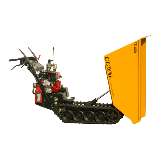
INTRODUCTION The WINGET TD650 Tracked Dumper is based on the HONDA HP500H Power Carrier donor unit and this Handbook must be read in conjunction with HONDA HP500H Owners Manual. The contents of this Handbook although correct at the time of publication, may be subject to alteration by the manufacturers without notice. -
Page 4: Declaration Of Conformity
DECLARATION CONFORMITY UKCA We: WINGET LIMITED Of Edgefold Industrial Estate, Plodder Lane, Bolton, Lancs, England BL4 0LR declare that the product type:- Machine Type:- 650Kg Tracked Dumper Model:- TD650 Serial Number:- 2156-2750 To which this declaration relates, with a net installed power of 3.6Kw and having been tested in accordance with the Conformity Assessment Procedure detailed in Schedule 9 of UKSI 2001/10701 and verified by;-... - Page 5 We also declare that the above equipment is also in accordance with the following Standards & Regulations:- EN ISO 12100:2010 EN ISO 13309:2010 ISO 3744:1995 UKSI 2018/764 Bolton 22.07.21 S. Hodge Place and date of issue ame and signature or equivalent marking of authorised person.
-
Page 6: Warranty Terms & Conditions
WARRANTY TERMS & CONDITIONS Winget Limited assures you that if any of the parts identified within the Parts section of this manual become defective due to faulty manufacture or materials within 12 months from the date of purchase, the part will be repaired or replaced under warranty free of charge by any authorised Winget Distributor. - Page 7 Winget Limited are used. The equipment must be serviced and maintained in accordance with the service schedules laid down in this handbook by Winget Limited. Evidence that these have been complied with may be required before Warranty claims are reimbursed.
- Page 8 If in doubt as to the suitability of this machine for a particular task refer to Winget Limited or Honda Power Equipment.
- Page 9 SAFE WORKING Never work under an unsupported or unpropped skip. Always ensure that any load is evenly distributed in the skip. Never carry loads or heap material in such a manner as to effect forward vision. Always take care when tipping non free running loads, be aware that wet concrete when carried in a skip can settle and stick in the skip when tipped thereby affecting the centre of gravity and stability.
- Page 10 SAFE WORKING Always avoid contact with the exhaust muffler, this can get very hot when the engine is running and remains so for some time afterwards. Always “dump” residual hydraulic pressure from the system before leaving the machine. Lower the skip; stop the engine, then move the hydraulic control lever several times in each direction.
- Page 11 SAFE WORKING suggests, skin cancer. ALWAYS wear protective gloves when handling oils and fuels whether topping up, draining or refilling. ALWAYS wash your hands if oils or fuels come into contact with the skin. Always store fuels in small quantities in the correct specially designed containers, which can be securely fastened.
-
Page 12: Safe Working
SAFE WORKING The following warning and advisory decals are applied to the dumper ‘CE’ Decal Wear Eye Protection Do Not Work Under Skip Hydraulic Control Safety Reminder Hydraulic Oil Keep Hands Clear Reads Ops Book Load Carrying Capacity Take Care With Non Free Running Loads... -
Page 13: Operation
OPERATION Never commence work until the daily service checks have been carried out. Only tip or Discharge the skip on level ground. The hydraulic system control valve and operating lever is mounted on top of the hydraulic tank on the left-hand side of the machine. The operating lever has three positions, forwards for ‘Dump’... - Page 14 OPERATION Allowing the skip to return onto the stops with force will damage the machine. Holding the lever to the rear until the skip is fully lowered will cause the relief valve located in the control valve to ‘blow off’ allowing the oil to return to tank.
-
Page 15: Maintenance And Service
MAINTENANCE AND SERVICE SERVICE SCHEDULE IMPORTANT; The Honda HP500H Power Carrier will require additional daily checks, services and adjustments in addition to those listed below, refer to the appropriate section of the HP500H Operators Handbook for details. Daily or every 10 operating hours check, or carry out the following:- Hydraulic oil level &... - Page 16 MAINTENANCE AND SERVICE CHANGING THE HYDRAULIC OIL AND CLEANING THE SUCTION STRAINER AND FILLER STRAINER/BREATHER Note:- the oil should only be changed when the engine is switched off, the skip is at rest on the stops and any residual hydraulic pressure remaining in the system has been ‘dumped’...
- Page 17 MAINTENANCE AND SERVICE strainer in solvent and examine for damage, as with the suction if punctured it should be replaced as it will no longer be effective. Refit in the reverse order taking care that the three small screws correctly enter the tank and are not cross-threaded. Wash the cap in solvent and dry off, ensure the vents in the cap are not blocked.
- Page 19 MAINTENANCE AND SERVICE PUMP; the hydraulic pump is driven directly from the crankshaft of the engine. FILTER; the suction strainer filter is located in the base of the tank as described above, hydraulic is drawn from the tank through the strainer to the pump.
- Page 20 MAINTENANCE AND SERVICE transmitting drive and has not broken. Check that the suction hose between the tank and pump is not damaged or deformed and restricting the flow of oil. Check that the system for leaks, loose hoses or fittings can allow air to be drawn into the system, causing the pump to cavitate and operate erratically.
-
Page 21: Technical Information
TECHNICAL INFORMATION DIMENSIONS Overall length 1.96m Overall width 0.68m Overall height 1 .13m Maximum height when skip tipped 1.340m Skip loading height 0.6m Skip discharge height 0.02m Unladen weight 264kg LUBRICANTS & CAPACITIES (Total Oils factory fill) Hydraulic Oil Azzola ZS46 Capacity 5 litres Grease Multis EP2... - Page 22 TECHNICAL INFORMATION MAXIMUM PAYLOAD CAPACITY On level ground 650kgs On gradients 350kgs MAXIMUM GRADIENT Maximum upward gradient (Laden) Maximum downward gradient (Laden) NOISE LEVELS Operators Ear 85LPA Directive 2000/14/EC & 99LWA 2001/1701 TRAVEL SPEED Forward travel 0-4.3 km/h Reverse travel 0-3.6 km/h VIBRATION AT HANDLEBARS Hand/Arm Vibration (EN1033)
- Page 23 PARTS INFORMATION TD650 PARTS SECTION...
- Page 24 TD650 Parts 1 - A - 1 SKIP & CHASSIS 1 - A - 1A HANDLEBAR SUPPORT RH 2 - A - 1 HYDRAULIC CIRCUIT 2 - A - 2 RAM TIPPING 3 - A -1 TANK & CONTROL VALVE 4 - A - 1 PUMP &...
- Page 25 1 - A - 1 TD650 Dumper...
- Page 26 SKIP & CHASSIS 1 - A - 1 Item Part no Serial no Description 1 V2005520 SKIP 2 V2005320 CHASSIS, subframe 3 V2005330 RAM, skip tipping 4 V2005341 PIN, ram rod 5 V2005342 PIN, ram body 6 267S09 WASHER, flat 7 44S16J PIN, split 10 V2005340...
- Page 27 1 - A - 1A TD650 Dumper...
- Page 28 HANDLEBAR SUPPORT RH 1 - A - 1A Item Part no Serial no Description 1 V2005765 /mid '07 Onwards SUPPORT, Handlebar R/H 2 153S01 "U" CLAMP 29mm 3 153S02 "U" CLAMP 32mm 4 267S05 WASHER, Flat 5 17S04 WASHER, Spring...
- Page 29 2 - A - 1 TD650 Dumper...
- Page 30 HYDRAULIC CIRCUIT 2 - A - 1 Item Part no Serial no Description 1 32S02J HOSE, pump to control valve 2 32S02J HOSE, suction, tank to pump 3 34S01N HOSE, control valve to ram lift 4 53S01J HOSE, control valve to ram lower 5 36S02UU HOSE, control valve return to tank 6 122S03...
- Page 31 2 - A - 2 TD650 Dumper...
- Page 32 RAM, skip tipping 2 - A - 2 Item Part no Serial no Description 1 V2005330 RAM, skip tipping assembly 2 V603576 GLAND, cylinder 3 V603577 CYLINDER, ram 4 V603578 ROD, piston 5 V603578 SCREW, grub 6 V603580 PISTON 7 V603013 BUSH 10 V603574 KIT, seals...
- Page 33 3 - A - 1 TD650 Dumper...
- Page 34 TANK & CONTROL VALVE 3 - A - 1 Item Part no Serial no Description 1 V2005357 1647/ VALVE, tip control, N.L.A. use item 1A ….. V603581 KIT, seals ….. V603582 VALVE, relief ….. V603583 HANDLE BODY ….. V603573 HANDLE, c/w nut & knob …..
- Page 35 4 - A - 1 TD650 Dumper...
- Page 36 PUMP & COUPLING 4 - A - 1 Item Part no Serial no Description 1 V2005363 1588/ PUMP, hydraulic, assembly "Rocquet" …… V603575 KIT, repair, c/w seals "Rocquet" 1 V2005363 /1589 PUMP, hydraulic, assembly "Albroco" …… V603669 KIT, repair, c/w seals "Albroco" ………………...
- Page 37 5- A - 1 TD650 Dumper...
- Page 38 DECAL, "WINGET", 310mm long 2 JPP1201 DECAL, "JOHNSON" 3 V2004744 DECAL, eye protection 4 V2005527 DECAL, "TD650" 5 V2005528 DECAL, load capacity TD650 6 V2004229 DECAL, read operator's handbook 7 V2003100 DECAL, hydraulic oil 8 V2005311 /2185 DECAL, noise LWA 101...
- Page 39 5- A - 2 TD650 Dumper...
- Page 40 DECALS 5 - A -2 Item Part no Serial no Description 1 V2003598 DECAL, British made 2 V2005448 DECAL, Do not track machine 3 V2005635 DECAL, Tracked Power Dumper 4 JD8090 DECAL, Honda Tracked Power Dumper (Supplied in sets one LH one RH) 5 V2006402 2186/ DECAL, UKCA Mark...
Need help?
Do you have a question about the TD650 and is the answer not in the manual?
Questions and answers