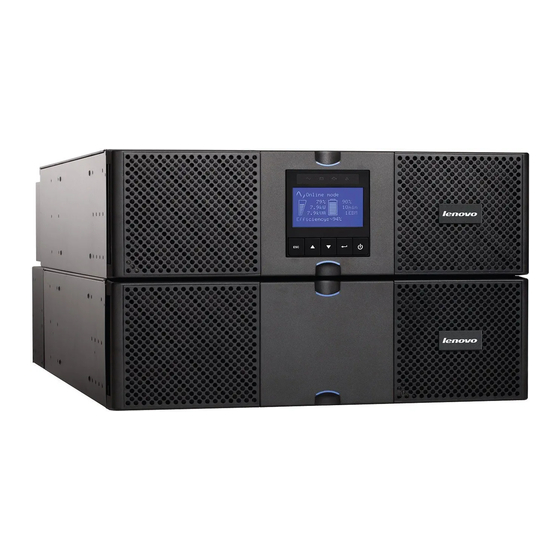
Lenovo 5594-5KX Replacing
Uninterruptible power supply (ups) front bezel including the lcd display
Hide thumbs
Also See for 5594-5KX:
- Installation and user manual (88 pages) ,
- Installation and user manual (76 pages)

Related Manuals for Lenovo 5594-5KX


Summary of Contents for Lenovo 5594-5KX
- Page 1 Replacing the Uninterruptible Power Supply (UPS) Front Bezel including the LCD Display Lenovo / IBM RT 5.0 kVA to RT 11.0 kVA UPS units Machine Types: 5594-5KX, 5594-6KX, 5594-8KX, 5594-9KX 5594-8PX, 5594-9PX...
- Page 2 In addition, be sure that you are familiar with the terms and conditions of the • Lenovo warranty for your server / hardware, which can be found at: https://support.lenovo.com/warrantylookup/warrantypolicy Check the warranty and maintenance agreement status for your server / •...
-
Page 3: Table Of Contents
Contents Contents Safety..........................i Safety statements..........................iv Guidelines for trained service technicians..................xi Inspecting for unsafe conditions......................xi Guidelines for servicing electrical equipment................xii Safety statements..........................xiii Product Safety...........................xxii Disclaimer........................xxiii Chapter 1 Replacing the Front Bezel Single Phase UPS Unit........1 Overview..............................1 Applicable UPS units..........................1 Attention!...............................1 Powering off the UPS unit........................2 Tools required............................3 Disassembling the LCD Display Bezel....................3 Assembling the LCD Display Bezel......................7... -
Page 4: Safety
Safety Safety These are the standard Safety instructions. Before installing this product, read the Safety Information. مقبل تركيب هظا المنتج ميجب مقراءة الملحاظات المانيه Antes de instalar este produto, leia as Informações de Segurança. Prije instalacije ovog produkta obavezno pročitajte Sigurnosne Upute. Pčed instalací... - Page 5 Safety Les sikkerhetsinformasjonen (Safety Information) før du installerer dette produktet. Przed zainstalowaniem tego produktu, należy zapoznać się z książką "Informacje dotyczące bezpieczeństwa" (Safety Information). Antes de instalar este produto, leia as Informações sobre Segurança. Pred inštaláciou tohto zariadenia si pečítaje Bezpečnostné predpisy. Pred namestitvijo tega proizvoda preberite Varnostne informacije.
-
Page 6: Safety Statements
Safety Safety statements These statements provide the caution and danger information that is used in this documentation. Important: Each caution and danger statement in this documentation is labelled with a number. This number is used to cross reference an English-language caution or danger statement with translated versions of the caution or danger statement in the Safety Information document. - Page 7 Safety Statement 1 Electrical current from power, telephone, and communication cables is hazardous. To avoid a shock hazard: Do not connect or disconnect any cables or perform installation, maintenance, or • reconfiguration of this product durinig an electrical storm. Connect all power cords to a properly wired and igrounded electrical outlet. •...
- Page 8 Safety Statement 2 CAUTION: When replacinig the lithium battery, use only Part Number 33F8354 or an equivalent type battery recommended by the manufacturer. If your system has a module containinig a lithium battery, replace it only with the same module type made by the same manufacturer.
- Page 9 Safety Statement 3 CAUTION: When laser products (such as CD-ROMs, DVD drives, fbre optic devices, or transmitters) are installed, note the followinig: Do not remove the covers. Removinig the covers of the laser product • could result in exposure to hazardous laser radiation. There are no serviceable parts inside the device.
- Page 10 Safety Statement 4 CAUTION: Use safe practices when liftinig. ≥ 18 kg (39.7 lb) ≥ 32 kg (70.5 lb) ≥ 55 kg (121.2 lb) Statement 5 CAUTION: The power control button on the device and the power switch on the power supply do not turn off the electrical current supplied to the device.
- Page 11 Safety Statement 8 CAUTION: Never remove the cover on a power supply or any part that has the followinig label attached. Hazardous voltaige, current, and enerigy levels are present inside any component that has this label attached. There are no serviceable parts inside these components. If you suspect a problem with one of these parts, contact a service technician.
- Page 12 Safety Statement 27 CAUTION: Hazardous movinig parts are nearby. Rack Safety Information, Statement 2 Always lower the levellinig pads on the rack cabinet. • Always install stabilizer brackets on the rack cabinet. • Always install servers and optional devices startinig from the bottom of the rack •...
-
Page 13: Guidelines For Trained Service Technicians
This section contains information for trained service technicians. Inspecting for unsafe conditions Use this information to help you identify potential unsafe conditions in a Lenovo product that you are working on. Each Lenovo product, as it was designed and manufactured, has required safety items to protect users and service technicians from injury. -
Page 14: Guidelines For Servicing Electrical Equipment
Safety Guidelines for servicing electrical equipment Observe these guidelines when you service electrical equipment. Check the area for electrical hazards such as moist foors, non-grounded power • extension cords, and missing safety grounds. Use only approved tools and test equipment. Some hand tools have handles that are •... -
Page 15: Safety Statements
Safety If an electrical accident occurs, use caution, turn off the power, and send another person • to get medical aid. Safety statements These statements provide the caution and danger information that is used in this documentation. Important: Each caution and danger statement in this documentation is labelled with a number. This number is used to cross reference an English-language caution or danger statement with translated versions of the caution or danger statement in the Safety Information document. - Page 16 Safety L001 DANGER Hazardous voltaige, current, or enerigy levels are present inside any component that has this label attached. Do not open any cover or barrier that contains this label. There are no serviceable parts inside these components. If you suspect a problem with one of these parts, contact a service technician.
- Page 17 Electrical voltaige and current from power, telephone, and communication cables are hazardous. To avoid a shock hazard: If Lenovo supplied a power cord(s), connect power to this unit only with the Lenovo- • provided power cord. Do not use the Lenovo-provided power cord for any other product.
- Page 18 Exchanige only with the Lenovo approved part. Recycle or discard the battery as instructed by local reigulations. In the United States, Lenovo has a process for the collection of this battery. For information, call 1-800-426-4333. Have the Lenovo part number for the battery unit available when you call.
- Page 19 Safety C009 CAUTION: 18 kg (39.7 lb) – 32 kg (70.5 lb) The weiight of this part or unit is between 18 and 32 kig (39.7 and 70.5 lb). It takes two persons to safely lift this part or unit. (C009) CAUTION: 32 kg (70.5 lb) –...
- Page 20 Safety CAUTION: ≥ 55 kg (121.2 lb) The weiight of this part or unit is more than 55 kig (121.2 lb). It takes specially trained persons, a liftinig device, or both to safely lift this part or unit. (C011) C022 CAUTION: This product miight be equipped with a hard-wired power cable.
- Page 21 Safety R001 Important: The followinig igeneral safety information should be used for all rack-mounted devices: DANGER Replacing the UPS Front Bezel including LCD...
- Page 22 Safety CAUTION: Do not install a unit in a rack where the internal rack ambient temperatures will • exceed the manufacturer’s recommended ambient temperature for all your rack- mounted devices. Do not install a unit in a rack where the air fow is compromised. Ensure that air fow •...
- Page 23 Safety Output power and ampere ratings Important: Make sure that the power receptacle is near the equipment and is easily accessible so that the uninterruptible power supply (UPS) can be disconnected quickly. To reduce the risk of fre, connect only to a circuit provided with branch circuit over-current protection with an ampere rating in accordance with the National Electrical Code (NEC), ANSI/NFPA 70 or your local electrical code.
-
Page 24: Product Safety
Safety Product Safety The UPS connection instructions and operations described in the manual must be • followed in the indicated order. Important: To reduce the risk of fre, the unit connects only to a circuit provided with • branch circuit over-current protection as described in this manual, in accordance with the National Electric Code, ANSI/NFPA 70. -
Page 25: Disclaimer
Web sites. The materials at those Web sites are not part of the materials for this Lenovo product, and use of those Web sites is at your own risk. -
Page 26: Chapter 1 Replacing The Front Bezel Single Phase Ups Unit
This document explains how to replace the UPS unit’s front bezel including LDC panel. The front bezel replacement part number is 00FP792. Applicable UPS units Lenovo RT5kVA 3U Rack or Tower UPS (200-240VAC), 5594-5KX • Lenovo RT6kVA 3U Rack or Tower UPS (200-240VAC), 5594-6KX •... -
Page 27: Powering Off The Ups Unit
Chapter 1 Replacing the Front Bezel Single Phase UPS Unit Powering off the UPS unit UPS LCD Control Panel 1. Press the button on the UPS LCD Control Panel at the front. The UPS goes into X On/Off Standby mode 2. -
Page 28: Tools Required
Chapter 1 Replacing the Front Bezel Single Phase UPS Unit Tools required #10T Torx screwdriver • Small fat-head screwdriver • Disassembling the LCD Display Bezel Start by grasping the top and bottom portion of the center plastic part of the bezel that encompasses the LCD, and pulling it away from the front of the unit Use the 10T Torx screwdriver to remove the two screws on the left of the display. - Page 29 Chapter 1 Replacing the Front Bezel Single Phase UPS Unit Using the T10 Torx screwdriver, remove the two screws on the right-hand side of the display Push the whole front panel bezel slightly to the right and then pull forward Replacing the UPS Front Bezel including LCD...
- Page 30 Chapter 1 Replacing the Front Bezel Single Phase UPS Unit Use a fat blade screwdriver to unlatch the display from the frame on one side, the other side should unlatch at the same time. Push the LCD display through the bezel so that it is in front of the bezel Remove the bracket on the back of the display by gently unlatching it from one side.
- Page 31 Chapter 1 Replacing the Front Bezel Single Phase UPS Unit Remove the two screws on the back panel using a T10 Torx screw driver Unlatch the back plate from the LCD assembly using the small latch Replacing the UPS Front Bezel including LCD...
-
Page 32: Assembling The Lcd Display Bezel
Chapter 1 Replacing the Front Bezel Single Phase UPS Unit 10. Hold the red plug with two fngers and carefully unplug it from the LCD circuit board. Repeat for second plug 11. Feed the ribbon cable assembly back through the round LCD hole in the bezel. Set the used bezel and LCD assembly aside. - Page 33 Chapter 1 Replacing the Front Bezel Single Phase UPS Unit Remove the bracket on the back of the display by gently unlatching it from one side. The other side should easily unlatch as well Remove the two screws on the back panel using a T10 Torx screw driver Unlatch the back plate from the LCD assembly using the small latch Replacing the UPS Front Bezel including LCD...
- Page 34 Chapter 1 Replacing the Front Bezel Single Phase UPS Unit Feed the ribbon cable assembly and red plugs though the round LCD hole in the new bezel Plug in the two red plugs into their corresponding receptacles in the order shown in the below left image Replacing the UPS Front Bezel including LCD...
- Page 35 Chapter 1 Replacing the Front Bezel Single Phase UPS Unit Reassemble the LCD display casing and screw it close Replacing the UPS Front Bezel including LCD...
- Page 36 Chapter 1 Replacing the Front Bezel Single Phase UPS Unit Carefully install the LCD assembly back into its holding frame Replacing the UPS Front Bezel including LCD...
- Page 37 Chapter 1 Replacing the Front Bezel Single Phase UPS Unit 10. Assemble the LCD assembly back into the bezel 11. Assembling the bezel with the LCD back onto the front of the UPS Replacing the UPS Front Bezel including LCD...
- Page 38 14. Complete assembling the bezel 15. Turn on the upstream utility power circuit breaker to which the UPS is connected to. The UPS front panel display illuminates and shows the Lenovo or IBM logo 16. Verify that the UPS status screen shows...
- Page 39 Chapter 1 Replacing the Front Bezel Single Phase UPS Unit 18. Check the UPS front panel display for active alarms or notices. Resolve any active alarms before continuing. See the Troubleshooting section of the relevant UPS User's Guide If the indicator is on, do not proceed until all alarms are clear.
-
Page 40: Chapter 2 Replacing The Front Bezel Three Phase Ups Unit
This document explains how to replace the UPS unit’s front bezel including LDC panel. The front bezel replacement part number is 01PE445. Applicable UPS units Lenovo RT8kVA 6U 3:1 Phase Rack or Tower UPS (380-415VAC), 5594-8PX • Lenovo RT11kVA 6U 3:1 Phase Rack or Tower UPS (380-415VAC), 5594-9PX •... -
Page 41: Powering Off The Ups Unit
Chapter 2 Replacing the Front Bezel Three Phase UPS unit Powering off the UPS unit UPS LCD Control Panel 1. Press the button on the UPS LCD Control Panel at the front. The UPS goes into X On/Off Standby mode 2. -
Page 42: Disassembling The Lcd Display Bezel
Chapter 2 Replacing the Front Bezel Three Phase UPS unit Disassembling the LCD Display Bezel 1. Start by grasping the top and bottom portion of the center plastic part of the bezel that encompasses the LCD, and pulling it away from the front of the unit 2. - Page 43 Chapter 2 Replacing the Front Bezel Three Phase UPS unit 5. Push the whole front panel bezel slightly to the right and then pull forward 6. Use a fat blade screwdriver to unlatch the display from the frame on one side, the other side should unlatch at the same time.
- Page 44 Chapter 2 Replacing the Front Bezel Three Phase UPS unit 7. Remove the bracket on the back of the display by gently unlatching it from one side. The other side should easily unlatch as well 8. Remove the two screws on the back panel using a T10 Torx screw driver Replacing the UPS Front Bezel including LCD...
- Page 45 Chapter 2 Replacing the Front Bezel Three Phase UPS unit 9. Unlatch the back plate from the LCD assembly using the small latch 10. Hold the red plug with two fngers and carefully unplug it from the LCD circuit board. 11.
-
Page 46: Assembling The Lcd Display Bezel
Chapter 2 Replacing the Front Bezel Three Phase UPS unit Assembling the LCD Display Bezel Grab the new LCD bezel assembly and turn it up-side down Use a fat blade screwdriver to unlatch the display from the frame on one side, the other side should unlatch at the same time. - Page 47 Chapter 2 Replacing the Front Bezel Three Phase UPS unit Remove the two screws on the back panel using a T10 Torx screw driver Unlatch the back plate from the LCD assembly using the small latch Feed the ribbon cable assembly and red plug though the round LCD hole in the new bezel Replacing the UPS Front Bezel including LCD...
- Page 48 Chapter 2 Replacing the Front Bezel Three Phase UPS unit Plug in the plug into the corresponding receptacle Reassemble the LCD display casing and screw it close Replacing the UPS Front Bezel including LCD...
- Page 49 Chapter 2 Replacing the Front Bezel Three Phase UPS unit Carefully install the LCD assembly back into its holding frame Replacing the UPS Front Bezel including LCD...
- Page 50 Chapter 2 Replacing the Front Bezel Three Phase UPS unit 10. Assemble the LCD assembly back into the bezel 11. Assembling the bezel with the LCD back onto the front of the UPS Replacing the UPS Front Bezel including LCD...
- Page 51 14. Complete assembling the bezel 15. Turn on the upstream utility power circuit breaker to which the UPS is connected to. The UPS front panel display illuminates and shows the Lenovo or IBM logo 16. Verify that the UPS status screen shows...
- Page 52 Chapter 2 Replacing the Front Bezel Three Phase UPS unit 18. Check the UPS front panel display for active alarms or notices. Resolve any active alarms before continuing. See the Troubleshooting section of the relevant UPS User's Guide If the indicator is on, do not proceed until all alarms are clear.
-
Page 53: Appendix A. Disclaimer
Web sites. The materials at those Web sites are not part of the materials for this Lenovo product, and use of those Web sites is at your own risk. -
Page 54: Appendix B. Notices
Any reference to a Lenovo product, program, or service is not intended to state or imply that only that Lenovo product, program, or service may be used. Any functionally equivalent product, program, or service that does not infringe any Lenovo intellectual property right may be used instead. -
Page 55: Customer Responsibilities For Code Installation
Lenovo or IBM machine) and other software updates in a timely manner from a Lenovo or IBM Internet Web site or from other electronic media, and following the instructions that Lenovo or IBM provides. You may request Lenovo or IBM to install Machine Code changes;... -
Page 56: Trademarks
Appendix B. Notices Trademarks Lenovo, the Lenovo logo, and "For Those Who Do" are trademarks or registered trademarks of Lenovo in the United States, other countries, or both. These and other Lenovo trademarked terms are marked on their frst occurrence in this information with the appropriate symbol (® or ™), indicating US registered or common law trademarks owned by Lenovo at the time this... -
Page 57: Printing This Document
Appendix B. Notices Printing this document This document has been created in the paper format DIN A4. The paper size is normed by the Deutsche Institut für Normung e. V. in norm DIN 476 and in International Standard ISO 216. The below illustration shows the difference of a DIN A4 sheet versus a US Letter sheet and the associated sizes in millimetres and inches. -
Page 58: Fonts Used In This Document
Appendix B. Notices Fonts used in this document This document has been written using various Open Source or free fonts. Some applications however will embed proprietary fonts such as WingDings etc. This is outwith the control of the author of this document. The fonts for this document were chosen in order to allow anybody to read this document as easy as possible. -
Page 59: Appendix C Getting Help And Technical Assistance
Appendix C Getting help and technical assistance Appendix C Getting help and technical assistance If you need help, service, or technical assistance or just want more information about Lenovo products, you will fnd a wide variety of sources available from Lenovo to assist you. -
Page 60: Gathering Information Needed To Call Support
Gathering information needed to call Support If you require warranty service for your Lenovo product, the service technicians will be able to assist you more effciently if you prepare the appropriate information before you call. You can also go to http://datacentersupport.lenovo.com/warrantylookup... -
Page 61: Collecting Service Data
Electronic Service Request. Collecting service data To clearly identify the root cause of a server issue or at the request of Lenovo Support, you might need collect service data that can be used for further analysis. Service data includes information such as event logs and hardware inventory.
Need help?
Do you have a question about the 5594-5KX and is the answer not in the manual?
Questions and answers