
Related Manuals for Gree GMV-120WLC-X


Summary of Contents for Gree GMV-120WLC-X
- Page 1 USER MANUAL [ GMV5 MINI OUTDOOR UNITS ] GMV-120WLC-X GMV-140WLC-X GMV-160WLC-X ORIGINAL INSTRUCTIONS, VER. 01 2020-12-04...
- Page 2 IMPORTANT NOTE: Read this manual carefully before installing or operating your new air conditioning unit. Make sure to save this manual for future reference.
- Page 3 (7) The final right to interpret for this instruction manual belongs to Gree Electric Appliances Inc. of Zhuhai.
- Page 4 Exception Clauses Manufacturer will bear no responsibilities when personal injury or property loss is caused by the following reasons: (1) Damage the product due to improper use or misuse of the product. (2) Alter, change, maintain or use the product with other equipment without abiding by the instruction manual of manufacturer.
-
Page 5: Table Of Contents
Contents 1 Safety Notices (Please Be Sure to Abide) ..............1 2 Product Introduction ....................3 2.1 Names of Main Parts ......................4 2.2 Combinations of Indoor and Outdoor Units ............... 5 2.3 Operating Range ......................5 3 Preparation before Installation ................. 6 3.1 Standard Parts ........................ -
Page 6: Safety Notices (Please Be Sure To Abide)
DC Inverter Multi VRF System 1 Safety Notices (Please Be Sure to Abide) WARNING: If not abide them strictly, it may cause severe damage to the unit or the people. NOTICE: If not abide them strictly, it may cause slight or medium damage to the unit or the people. - Page 7 DC Inverter Multi VRF System Be sure to use special accessories and parts for If refrigerant leakage installation to prevent water happens, please ventilate the leakage, electric shock and room immediately. fire hazard, etc. Diameter of power cord When the power cord is should be large enough.
-
Page 8: Product Introduction
Gree Electric Appliances, Inc. of Zhuhai will not assume responsibility for any personal injury or property loss caused by improper installation, improper debugging, unnecessary repair or not following the instructions of this manual. -
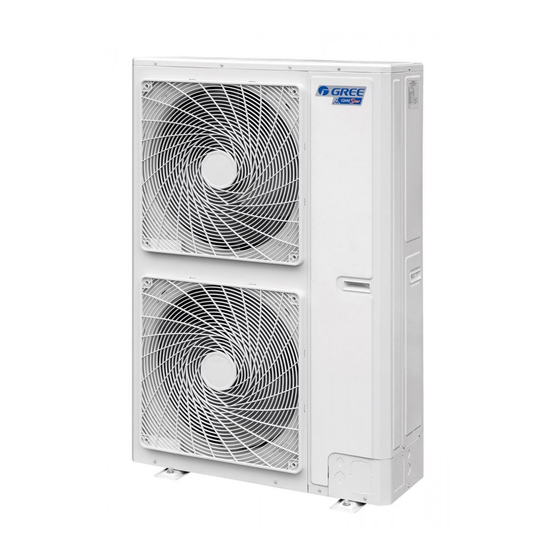
Page 9: Names Of Main Parts
DC Inverter Multi VRF System 2.1 Names of Main Parts Fig.1 ① ② ③ ④ ⑤ Electric box Name Motor Fan blade Gas pipe valve Liquid pipe valve assembly Fig.2 ① ② ③ ④ ⑤ Electric box Name Motor Fan blade Gas pipe valve Liquid pipe valve assembly... -
Page 10: Combinations Of Indoor And Outdoor Units
DC Inverter Multi VRF System Fig.3 ① ② ③ ④ ⑤ Electric box Name Motor Fan blade Gas pipe valve Liquid pipe valve assembly 2.2 Combinations of Indoor and Outdoor Units (1) See below the number of indoor units that can be connected to the outdoor unit. (2) The total capacity of indoor units should be within 50%~135% of that of the outdoor unit. -
Page 11: Preparation Before Installation
DC Inverter Multi VRF System 3 Preparation before Installation NOTE!: Graphics here are only for reference. Please refer to actual products. Unspecified dimensions are all in mm. 3.1 Standard Parts Please use the supplied standard parts as required. Parts for Outdoor Unit Name Appearance Remark... -
Page 12: Installation Site
DC Inverter Multi VRF System 3.2 Installation Site Forbidden item! Improper operation might lead to personal injury or even death. Item needs to be followed. Improper operation might lead to personal injury or property damage. Select a location which is strong The installation position should enough to hold unit’s weight so withstand strong wind, typhoon... -
Page 13: Installation Instruction
DC Inverter Multi VRF System 4 Installation Instruction NOTE!: Graphics here are only for reference. Please refer to actual products. Unspecified dimensions are all in mm. 4.1 Dimension of Outdoor Unit and Mounting Hole Unit Outline and Installation Dimension(mm). Fig.5 Unit: mm Model GMV-120WL/C-T... - Page 14 DC Inverter Multi VRF System Fig.6 Unit: mm Model GMV-80WL/A-T GMV-100WL/A-T GMV-121WL/A-T GMV-80WL/C-T GMV-100WL/C-T GMV-121WL/C-T GMV-141WL/C-T...
-
Page 15: Connection Pipe
DC Inverter Multi VRF System 4.2 Connection Pipe 4.2.1 Schematic Diagram of Piping Connection Fig.7... - Page 16 DC Inverter Multi VRF System 4.2.2 Allowable Length and Height Difference of Connection Pipe Y type branch joint is adopted to connect indoor and outdoor units. Connecting method is shown in the figure below: NOTE!: Equivalent length of one Y-type branch is 0.5m. Fig.8 Allowable Length and Height Difference of Connection Pipe Piping parameters of GMV-80WL/A-T, GMV-100WL/A-T, GMV-121WL/A-T GMV-80WL/C-T, GMV-100WL/C-T, GMV-121WL/C-T.
- Page 17 DC Inverter Multi VRF System 4.2.3 Dimension of Pipe (Main Pipe) from ODU to the 1st Indoor Branch Dimension of pipe from ODU to the 1st indoor branch will be determined by the dimension of outdoor connection pipe. Fig.9 Dimension of outdoor connection pipe. Pipe dimension Basic module Gas pipe (mm)
- Page 18 DC Inverter Multi VRF System 4.2.4 Selection of Indoor Branches Select indoor branches according to the total capacity of downstream indoor units. If the capacity exceeds that of the outdoor unit, capacity of outdoor unit prevails. Fig.10 R410A Refrigerant system Total capacity of downstream indoor units X (kW) Model X<20...
-
Page 19: Installation Of Connection Pipe
DC Inverter Multi VRF System 4.2.6 Dimension of Pipe between Indoor Branch and IDU Dimension of pipe between indoor branch and IDU should be consistent with the dimension of indoor pipe. Fig. 12 Rated capacity of IDU C(kW) Gas pipe (mm) Liquid pipe (mm) C≤2.8 Φ9.52... - Page 20 DC Inverter Multi VRF System tool to fix the flared nut into the pipe (as shown in Fig.13). (4) Check if the flared part is flaring evenly and if there is any crack. Fig. 13 4.3.3 Pipe Bending (1) Reshape the pipe by hand. Be careful not to damage the pipe. Fig.
- Page 21 DC Inverter Multi VRF System (7) When connecting IDU with connection pipe, do not pull the big and small joints of IDU with force in case the capillary tube or other tubes have cracks and cause leakage. Pipe dimension Tightening torque Φ6.35mm 15~30(N·m) Φ9.52mm...
- Page 22 DC Inverter Multi VRF System Fig.19 4.3.6 Installation of Y-type Branch (1) Y-type Branch. Fig. 20 (2) Y-type branch has several pipe sections with different dimension, which facilitates to match with various copper pipes. Use pipe cutter to cut in the middle of the pipe section that is of proper dimension and remove burrs as well.
- Page 23 DC Inverter Multi VRF System 1) To avoid condensate or water leakage on the connection pipe, the gas pipe and liquid pipe must be wrapped with thermal insulating material and adhesive tape for insulation from the air. 2) Thermal insulating material shall be able to bear the pipe temperature. For heat pump unit, liquid pipe should bear 70°C or above and gas pipe should bear 120°C or above.
-
Page 24: Disassembly Of Compressor Feet
DC Inverter Multi VRF System 4.4 Disassembly of Compressor Feet In order to prevent unit from damage during transportation, 2 metal pieces are fitted to outdoor unit’s compressor feet before unit leaves factory. See Fig.23. Fig. 23 When installing the unit, metal pieces for transportation must be removed. Then fasten the binding nuts again and wrap back soundproofing cotton. - Page 25 DC Inverter Multi VRF System 4.5.2 Refrigerant Adding (1) Refrigerant quantity of outdoor unit before delivery: GMV-80WL/A-T GMV-100WL/A-T GMV-121WL/A-T Model GMV-80WL/C-T GMV-100WL/C-T GMV-121WL/C-T Refrigerant Qty (kg) 1.80 1.80 2.00 GMV-141WL/C-T GMV-120WL/C-T GMV-160WL/C-T Model GMV-140WL/C-T GMV-120WL/C-X GMV-160WL/C-X GMV-140WL/C-X Refrigerant Qty (kg) 3.30 3.30 3.30...
-
Page 26: Electric Wiring
DC Inverter Multi VRF System Liquid pipe: Pipe size Φ9.52 Φ9.52 Φ9.52 Φ6.35 Length Pipe size Φ9.52 Φ6.35 Φ6.35 Φ6.35 Length Total length of each liquid pipe. Φ9.52: A+B+C+a=10+5+5+3=23m. Φ6.35: D+b+c+d=5+3+2+1=11m. Quantity of indoor unit: 4 sets. Therefore, the minimum quantity of additional refrigerant = (23×0.054+11×0.022) + (4-2) ×0.3= 2.084kg. - Page 27 DC Inverter Multi VRF System (10) Grounding Requirements. 1) Air conditioner belongs to class I electrical appliance, so it must be securely grounded. 2) The yellow-green wire inside the unit is a ground wire. Do not cut it off or secure it with tapping screws, otherwise it will lead to electric shock.
- Page 28 DC Inverter Multi VRF System (2) Selection of circuit breaker and power cord. Circuit breaker Number of ground Number of power cord Model Power supply capacity wire× Min sectional × Min sectional area area (mm 220~240V 50Hz GMV-80WL/A-T 1×2.5 2×2.5 208~230V 60Hz 220~240V 50Hz GMV-100WL/A-T...
- Page 29 DC Inverter Multi VRF System (4) For engineering wiring, please refer to the wiring diagram provided with the unit. Fig. 28 Engineering Wiring View of GMV-80WL/A-T, GMV-100WL/A-T, GMV-121WL/A-T, GMV-80WL/C-T, GMV-100WL/C-T and GMV-121WL/C-T Fig. 29 Engineering Wiring View of GMV-141WL/C-T Fig. 30 Engineering Wiring View of GMV-120WL/C-T, GMV-140WL/C-T, GMV-160WL/C-T, GMV-120WL/C-X, GMV-140WL/C-X and GMV-160WL/C-X...
-
Page 30: Check Items After Installation And Test Operation
DC Inverter Multi VRF System 5 Check Items after Installation and Test Operation 5.1 Check Items after Installation Check items Possible conditions due to improper installation Check Each part of the unit is installed securely? Unit may drop, shake or emit noise. Gas leakage test is taken or not? Insufficient cooling (heating) capacity. - Page 31 DC Inverter Multi VRF System Service Manual. (9) Before test operation, make sure unit is power on and compressor has been preheated for more than 8 hours. Touch the unit to check whether it’s normally preheated. If yes, start test operation.
- Page 32 DC Inverter Multi VRF System Description of each stage of debugging progress —— Debugging code Progress code Status code Code meaning and operation LED1 LED2 LED3 method Progress Display Display Display Code Code Code status status status Communication between master ODU and driver has error.
- Page 33 DC Inverter Multi VRF System Description of each stage of debugging progress —— Debugging code Progress code Status code Code meaning and operation LED1 LED2 LED3 method Progress Display Display Display Code Code Code status status status Preheat time for compressor is less than 8 hours.
- Page 34 DC Inverter Multi VRF System Description of each stage of debugging progress —— Debugging code Progress code Status code Code meaning and operation LED1 LED2 LED3 method Progress Display Display Display Code Code Code status status status Ready for units to start debugging. Press main board’s SW7 button to Blink confirm startup of debugging.
- Page 35 DC Inverter Multi VRF System Description of each stage of debugging progress —— Debugging code Code meaning and operation method Progress Code Display status “00~16” displays the quantity of indoor unit. Confirm the number manually. If the number is not consistent the display one, cut off power of IDU and ODU and check whether Display 04/00~16...
- Page 36 DC Inverter Multi VRF System Description of each stage of debugging progress —— Debugging code Code meaning and operation method Progress Code Display status Preheat time for compressor is less than 8 hours. Display will be as in the left until the preheat time reaches 8 hours. Press Display main board’s SW3 button to confirm manually that the 08/U0...
- Page 37 DC Inverter Multi VRF System 5.2.3 Appendix: Reference of Normal Operation Parameters Debug item Parameter name Unit Reference Outdoor °C —— temperature When compressor starts, discharge temp in cool mode is within 70°C~105°C and at least 10°C higher than the high Compressor °C pressure saturation temp.
-
Page 38: Common Malfunctions And Troubleshooting
Reduce heat resources. room. Filter is blocked and dirty. Clean the filter. NOTE!: If problem cannot be solved after checking the above items, please contact Gree service center and describe the cases and models. (2) Following circumstances are not malfunctions. Malfunction Reason... -
Page 39: Error Indication
DC Inverter Multi VRF System Malfunction Reason Unit blows out Unit starts up after not operating for a Dust in indoor unit is blown out. dust. long time. Unit emits odor. Under operation. Unit absorbs the room odor and then blows it out. 7 Error Indication Inquiry method of error indication: combine division symbol and content symbol to check the corresponding error. - Page 40 DC Inverter Multi VRF System Error Code Content Error Code Content (uniform) (uniform) Driving board of compressor operates Driving board of fan operates abnormally abnormally (uniform) (uniform) Voltage protection of driving board power of Voltage protection of driving board power compressor (uniform) of fan (uniform) Reset protection of driving module of...
-
Page 41: Maintenance And Care
(5) If unit starts up after not operating for a long time, it should be power on 8 hours before operation starts so as to preheat the outdoor compressor. (6) Check whether outdoor unit is securely installed. If there is any problem, please contact Gree authorized service center. -
Page 42: Maintenance After Seasonal Use
Otherwise, it may lead to danger. Use nitrogen or refrigerant to conduct the tests. 9 After-sales Service If there’s quality defect or other problems in the product, please contact Gree local after-sales service department for help. Warranty must be based on the following conditions: (1) Product’s initial startup must be performed by professional technicians from Gree service... - Page 43 The value GWP: 2088 (1 kg R410A = 2,088 t CO GWP = Global Warming Potential In case of quality problem or other please contact your local supplier or authorized service center. Emergency number: 112 PRODUCER GREE ELECTRIC APPLIANCES, INC. OF ZHUHAI West Jinji Rd, Qianshan, 519070 Zhuhai China REPRESENTATIVE GREE Czech &...
Need help?
Do you have a question about the GMV-120WLC-X and is the answer not in the manual?
Questions and answers