
Related Manuals for Riello REG 35.5


Summary of Contents for Riello REG 35.5
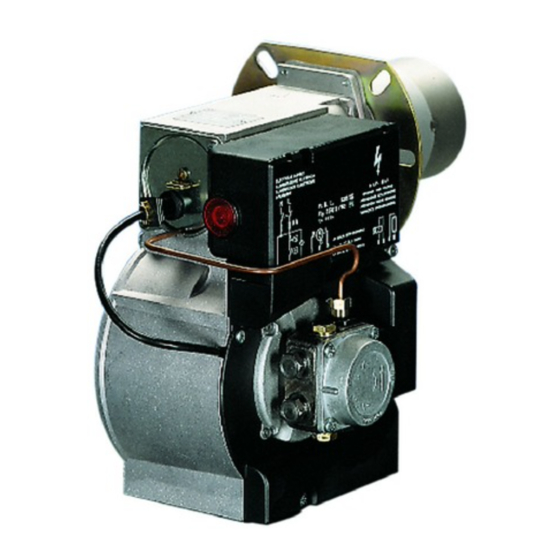
- Page 1 Installation, use and maintenance instructions Light oil burner CODE MODEL TYPE 3772216 REG 35.5 722T 2902416 (5) - 05/2016...
-
Page 3: Technical Data
TECHNICAL DATA Output - Thermal power 2.3 – 5 kg/h – 27 – 60 kW Fuel Light oil, viscosity 4 – 6 mm /s at 20 °C ± Electrical supply Single phase 230 V 50Hz Run current 0.75 A – 2750 rpm – 289 rad/s – Capacitor 4 F Motor Ignition transformer Secondary 8 kV –... -
Page 4: Hydraulic Systems
HYDRAULIC SYSTEMS Fig. 4 Before starting the burner make sure that the return pipe-line is not clogged. An excessive back pressure would cause the damage of the pump seal. The pump is designed for operation on a two line sys- tem. -
Page 5: Electrical Connections
REMOVAL OF NOZZLE HOLDER ASSEMBLY ELECTRICAL CONNECTIONS (Fig. 8) – Disconnect the oil pipe fitting (1) from the pump. Take out the – Remove the protection crankcase (8, photoresistance (2), loosen the retainer screws (3) of the cover. fig. 1, page 1) after removing the 3 –... - Page 6 COMBUSTION ADJUSTMENT In conformity with Efficiency Directive 92/42/EEC the application of the burner on the boiler, adjustment and testing must be carried out observing the instruction manual of the boiler, including verification of the CO and concentration in the flue gases, their temperatures and the average temperature of the water in the boiler. To suit the required appliance output, choose the proper nozzle and adjust the pump pressure, the setting of the combustion head, and the air damper opening in accordance with the following schedule.
- Page 8 RIELLO S.p.A. I-37045 Legnago (VR) Tel.: +39.0442.630111 http:// www.riello.it http:// www.riello.com Subject to modifications...