
Related Manuals for Riello RS 190 EV


Summary of Contents for Riello RS 190 EV
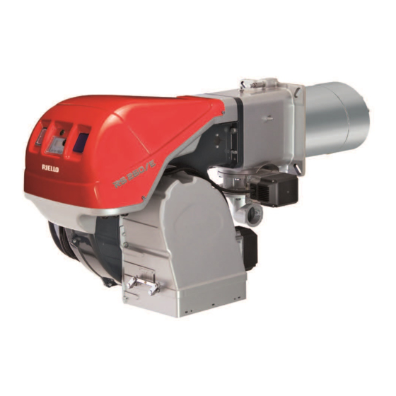
- Page 1 Installation, use and maintenance instructions Forced draught gas burners Progressive two stage or modulating operation CODE MODEL C9327710 RS 190/EV C9328700 - C9328710 RS 250/EV 20094575 (4) - 05/2018...
- Page 2 Original instructions...
-
Page 3: Table Of Contents
Contents Information and general instructions ..............3 Information about the instruction manual . - Page 4 Contents 5.4.1 Adjusting gas/air delivery............... 30 5.4.2 Air/fuel control and power modulation system .
-
Page 5: Information And General Instructions
Information and general instructions Information and general instructions Information about the instruction manual 1.1.1 Introduction WARNING: MOVING PARTS The instruction manual supplied with the burner: This symbol indicates that you must keep limbs is an integral and essential part of the product and must not be away from moving mechanical parts;... -
Page 6: Delivery Of The System And The Instruction Manual
Information and general instructions The system supplier must carefully inform the user about: 1.1.4 Delivery of the system and the instruction – the use of the system; manual – any further tests that may be required before activating the When the system is delivered, it is important that: system;... -
Page 7: Safety And Prevention
Safety and prevention Safety and prevention Introduction The burners have been designed and built in compliance with facturer; current regulations and directives, applying the known technical the type and pressure of the fuel, the voltage and frequency of rules of safety and envisaging all the potential danger situations. the electrical power supply, the minimum and maximum deliv- eries for which the burner has been regulated, the pressurisa- It is necessary, however, to bear in mind that the imprudent and... -
Page 8: Technical Description Of The Burner
Technical description of the burner Technical description of the burner Burner models designation Model Code Certification RS 190/EV 20044217 RS 250/EV 20036703 Technical data Model RS 190/EV RS 250/EV Output Maximum 1420 - 2542 1387 - 2941 (2674*) MBtu/hr 4845 - 8673 4732 - 10034 (9122*) Minimum MBtu/hr... -
Page 9: Electrical Data
Technical description of the burner Electrical data Fan motor IE2/EPACT Model RS 190/EV RS 250/EV Control circuit power supply V/Ph/Hz 120/1/60 Main electrical supply (+/- 10%) V/Ph/Hz 208-220/3/60 Fan motor 3500 3500 208-230 208-230 18.6 18.6 Ignition transformer V1 - V2 120 V - 1 X 8 kV I1 - I2 1.6 A - 20 mA... -
Page 10: Burner Models Designation
Technical description of the burner Burner models designation Model Code RBNA code Main Voltage Flame safeguard 208-220/3/60 RS 190/EV 20044217 C9327710 460/3/60 Burner mounted 575/3/60 C9328700 208-220/3/60 RS 250/EV 20036703 C9328710 460/3/60 Burner mounted 575/3/60 Packaging - weight - Approximate measurements ... -
Page 11: Burner Description
Technical description of the burner Burner description View from A 35 40 36 23 42 20097557 45 46 47 48 37 31 Fig. 3 Combustion head 30 Flame stability disc Burner pilot 31 Horn Screw for combustion head adjustment 32 “ALARM SILENCE” button Maximum gas pressure switch 33 “POWER ON”... -
Page 12: Firing Rate
Technical description of the burner Firing rate The maximum output is chosen within area A of the Fig. 4. The firing rate was obtained considering a room The minimum output must not be lower than the minimum limit of temperature of 68 °F and an atmospheric pressure the diagrams. -
Page 13: Procedure To Refer Burner Operating Condition At An Altitude And/Or At A Combustion Supporter Air Temperature Different To The Standard Values (328 Ft Above Sea Level, 68 °F)
Technical description of the burner 3.9.1 Procedure to refer burner operating condition at an altitude and/or at a combustion supporter air temperature different to the standard values (328 ft above sea level, 68 °F). AIR TEMPERATURE Altitude Altitude bar. press. bar. -
Page 14: Control Box For The Air/Fuel Ratio (Lmv37.4
WARNING The LMV37.4... is a safety device! Do not open, interfere with or modify the unit. Riello S.p.A. will not assume responsibility for any damage resulting from unauthorized inter- ference! All activities (mounting, installation and service work, etc.) must be performed by qualified staff. - Page 15 Technical description of the burner Technical data LMV37.4... basic unit Mains voltage AC 120 V -15 % / +10 % Mains frequency 50 / 60 Hz ±6 % Power consumption < 30 W (typically) Safety class I, with parts according to II and III to DIN EN 60730-1 Terminal loading Unit fuse F1 (internally) 6.3 AT...
- Page 16 Technical description of the burner Operation sequence of the burner Operation Startup Shutdown Valve proving TSA2 TSA1 Phase number Safety limit thermostat (STB) Control thermostat or pressurestat (R) Flame signal (FS) Air pressure switch (LP) Pressure switch-min (Pmin) Pressure switch-max (Pmax) Valve proving / leakage test (P LT) POC (alternative to Pmax) Motor (M)
-
Page 17: Actuators (Sqm33.5
Technical description of the burner 3.12 Actuators (SQM33.5...) Warning notes To avoid injury to persons, damage to property or the environment, the following warning notes should be observed! WARNING Do not open, interfere with or modify the actua- tors! All activities (mounting, installation and service work, etc.) must be performed by qualified staff. -
Page 18: Installation
Installation Installation Notes on safety for the installation After carefully cleaning all around the area where the burner will be The installation of the burner must be carried out by installed, and arranging the correct lighting of the environment, pro- qualified personnel, as indicated in this manual and ceed with the installation operations. -
Page 19: Boiler Plate
Installation Boiler plate Make holes in the plate shutting off the combustion chamber, as il- lustrated in Fig. 10. The position of the threaded holes can be marked using the ther- mal insulation screen supplied with the burner. For boilers with front flue passes 13)(Fig. 11) or flame inver- sion chambers, a protection in refractory material 11) must be inserted between the boiler refractory 12) and the blast tube 10). -
Page 20: Electrode Positioning
Installation Electrode positioning To verify the correct position of the ignition electrode (Fig. 12), you need to separate the combustion head from the rest of the burner. Proceed as follows: loosen the 4 screws 3)(Fig. 11) and remove the cover 1); ... -
Page 21: Combustion Head Adjustment
Installation Combustion head adjustment At this point of the installation, the combustion head is fixed to the Two adjustments of the head are foreseen: air adjustment boiler as shown in Fig. 13. gas adjustment It is therefore especially easy to adjust, and this adjustment de- pends only on the maximum output of the burner. - Page 22 Installation Once the combustion head adjustment is completed: push the burner on the sliding bars 3) at approximately 4” from the pipe coupling 4) - burner in the position shown in Fig. 17; insert the electrode cable, then slide the burner as far as the pipe coupling - burner in the position shown in Fig.
-
Page 23: Gas Supply
Installation Gas supply 4.9.1 Gas train The gas train is type-approved according to standard UL 795 and is supplied separately from the burner. The gas train can enter the burner from the right or left side, depending on which is the most convenient. ... -
Page 24: Gas Pressure
Installation 4.9.3 Gas pressure The diagram (Fig. 21) and (Fig. 22) show minimum load losses at combustion head depending on the maximum burner output oper- ation with natural gas (G 20). RS 190/EV D3190 Burner output operation Fig. 21 D10473 RS 250/EV Burner output operation Fig. - Page 25 Installation Gas pressure is measured at the test point 1)(Fig. 23), with: RS 190/EV • Combustion chamber at 0 mbar p2 “WC MBtu/hr • Burner working at maximum output • Ring nut 2)(Fig. 15) adjusted as in the diagram of Fig. 14 4848 1421 5302...
-
Page 26: Electrical Wiring
Installation 4.10 Electrical wiring Notes on safety for the electrical wiring The electrical wiring must be carried out with the electrical supply disconnected. Electrical wiring must be carried out by qualified personnel and in compliance with the regulations currently in force in the country of destination. - Page 27 Installation Key (Fig. 25) It is very important to shield the motor cable 1) as Motor cable power supply (coming from the inverter) shown in Fig. 25. Single phase supply cable It is very important to fix the cable shielding as Connection cable between the inverter and the electronic cam WARNING shown in Fig.
-
Page 28: Installation Of Shielded Cables
Installation 4.10.1 Installation of shielded cables In the case of clamp type A: unscrew the screw until space is created for inserting the shielding of the shielded cable A1)(Fig. 26); insert the shielded cable with the shielding inside the clamp A2);... -
Page 29: Inverter Connection
Installation 4.10.3 Inverter connection Treatment of cables Countermeasures against cable noise Following, it is reported an example how to con- nect the Inverter. The treatment of cables is the most important countermeasure. For further information, please refer to the relevant The machinery manufacturers are requested Inverter instruction manual. -
Page 30: Motor Connection At 208-230 Or 460V
Installation 4.11 Motor connection at 208-230 or 460V Please, pay attention to the indications in case of modification of the motors, manufactured for 208-230/460 IE3 voltage, maintenance, or substitution. NEMA Premium Efficiency voltage, have the same connection than IE2/Epact motors, but differ- WARNING ent connection than IE1 motors no more star/delta but star/double star. -
Page 31: Start-Up, Calibration And Operation Of The Burner
Start-up, calibration and operation of the burner Start-up, calibration and operation of the burner Notes on safety for the first start-up The first start-up of the burner must be carried out Check the correct working of the adjustment, com- by qualified personnel, as indicated in this manual mand and safety devices. -
Page 32: Combustion Air Adjustment
Start-up, calibration and operation of the burner For the start-up procedure and the parameters calibration, refer to the specific instruction man- ual of the LMV37... electronic cam supplied with WARNING the burner. 20097538 LOCAL REMOTE Fig. 35 Combustion air adjustment Fuel/combustion air must be synchronized with the relevant servo- cam;... -
Page 33: Final Calibration Of The Pressure Switches
Start-up, calibration and operation of the burner Final calibration of the pressure switches 5.5.1 Air pressure switch The air pressure switch is connected in differential (Fig. 37) and is activated by both the negative pressure of the air intake and the air pressure from the fan. -
Page 34: Final Checks (With The Burner Working)
Start-up, calibration and operation of the burner Final checks (with the burner working) Open the control limit operation The burner must stop Open the high limit operation Rotate the maximum gas pressure switch knob to the ... -
Page 35: Maintenance
Maintenance Maintenance Notes on safety for the maintenance The periodic maintenance is essential for the good operation, safe- Before carrying out any maintenance, cleaning or checking opera- ty, yield and duration of the burner. tions: It allows you to reduce consumption and polluting emissions and to keep the product in a reliable state over time. -
Page 36: Flame Signal Measurement
Maintenance extract the sensor 2); clean the glass cover from any dust that may have accumu- lated. Be extremely careful while troubleshooting the detector; line voltage is present on some of the terminals when power is on. ... -
Page 37: Opening The Burner
Maintenance Opening the burner Disconnect the electrical supply from the burn- DANGER In order to open the burner, proceed as follows: loosen the 4 screws 1) (Fig. 42) and remove the cover 2); install the 2 extensions 9) on the sliding bars 4) and re-screw the screws 8);... -
Page 38: A Appendix - Spare Parts
Appendix - Spare parts Appendix - Spare parts 20094575... - Page 39 Appendix - Spare parts CODE DESCRIPTION • • 20073258 AIR DAMPER ASSEMBLY • • 3013683 PROTECTION GRATE • • 3013682 SOUND DAMPING • • 3003763 INSPECTION WINDOW • • 3013686 BAR EXTENSION • • 3012976 • • 20086561 COVER • • 20075921 INSPECTION WINDOW •...
- Page 40 Appendix - Spare parts CODE DESCRIPTION • • 3007891 SEAL • • 3013055 TUBE • • 3012969 GAS PRESSURE SWITCH • • 3012956 TRANSFORMER • 3013977 GAS REGULATOR • 3012588 DISC • 3013693 DISC • • 3012841 BASE • • 20010969 RELAY •...
-
Page 41: B Appendix - Accessories
Appendix - Accessories Appendix - Accessories Gas train according to UL Standards The installer is responsible for the supply and instal- lation of any required safety device(s) not indicated in this manual. WARNING 20094575... -
Page 42: Appendix - Burner Start Up Report
Appendix - Burner start up report Appendix - Burner start up report Model number: Serial number: Project name: Start-up date: Installing contractor: Phone number: Model number: Serial number: Project name: Start-up date: Installing contractor: Phone number: GAS OPERATION : Low Fire Gas Supply Pressure: High Fire : Low Fire... - Page 44 RIELLO S.p.A. I-37045 Legnago (VR) Tel.: +39.0442.630111 http:// www.riello.com RIELLO BURNERS NORTH AMERICA http://www.riello.ca 35 Pond Park Road 2165 Meadowpine Blvd Hingham, Massachusetts, Mississauga, Ontario U.S.A. 02043 1-800-4-RIELLO Canada L5N 6H6 Subject to modifications...
Need help?
Do you have a question about the RS 190 EV and is the answer not in the manual?
Questions and answers