
Related Manuals for Gree UML600H/A-MP


Summary of Contents for Gree UML600H/A-MP
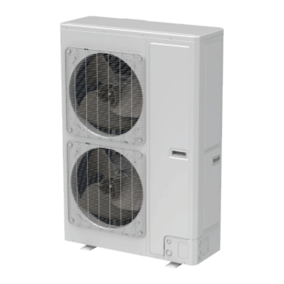
- Page 1 Ducted Type Split Air-Conditioner Units (GC201912-Ⅰ) Capacity: 40/50/60kW Rate Frequency: 50Hz Operation Range:18℃~48℃...
- Page 2 Contents PRODUCT .......................... 4 1 Product List ........................5 2 Nomenclature ......................... 6 3 Specifications ......................... 7 CONTROL .......................... 9 1 Wired Controller ......................10 1.1 Control Panel ........................10 1.2 Installation and Removal ..................... 12 2 Remote Controller YAP1F .................... 15 3 Monitoring Software ....................
- Page 3 4.5 Fixing and Damping of Unit ....................64 4.6 Outline Dimension and Position of Installation Hole ............. 64 4.7 Installation Space Requirement ................... 66 5 Pipeline Design of Refrigerant ..................67 5.1 Notices for Pipeline Design ....................67 5.2 Allowable Length and Fall for Refrigerant Pipe In IDU and ODU ......... 68 5.3 Design of Oil Loop .......................
- Page 4 PRODUCT...
- Page 5 GREE Duct type Ducted Type Split Air-Conditioner Units 1 Product List Capacity Appearance Units (kW/Ton) Model Name Series Cooling Outdoor Indoor UMLD400W/A-M(P) 38.1/10.668 UMD400PH/A-M(P) Duct R410A UML500H/A-M(P) Type 47.7/13.356 UM500PH/A-M(P) UML600H/A-M(P) 56.5/15.82 UM600PH/A-M(P)
- Page 6 GREE Duct type Ducted Type Split Air-Conditioner Units 2 Nomenclature Outdoor Model Cooling Function Compressor Meaning Product code Climate type capacity Outdoor unit type code frequency code Fixed speed – Nominal W – Side discharge Representing General unitary T1 working...
- Page 7 GREE Duct type Ducted Type Split Air-Conditioner Units 3 Specifications UMD400PH/A-M(P) Model(Indoor/Outdoor) UMLD400W/A-M(P) Combination Mode Refrigeration Capacity Cooling Capacity 38.1 Heating Capacity Power Supply 3N~/380-415V/(50Hz) Cooling Power Input Heating Cooling 28.8 Current Input Heating Sound Pressure Level(Indoor/ Outdoor) dB(A) 56/66...
- Page 8 GREE Duct type Ducted Type Split Air-Conditioner Units UM500PH/A-M(P) Model(Indoor/Outdoor) UML500H/A-M(P) Net Weight 230/350 (Indoor/ Outdoor) UM600PH/A-M(P) Model(Indoor/Outdoor) UML600H/A-M(P) Combination Mode Refrigeration Capacity Cooling Capacity 56.5 Heating Capacity Power Supply 380V 3N~ 50Hz Cooling Power Input Heating Cooling 50.1 Current Input...
- Page 9 GREE Duct type Ducted Type Split Air-Conditioner Units CONTROL...
- Page 10 GREE Duct type Ducted Type Split Air-Conditioner Units 1 Wired Controller 1.1 Control Panel Fig.2.1 Appearance of wired controller Fig2.2 LED graphics of wired controller Table 2.1 LED display instruction Symbols Instructions Up and down swing function. Left and right swing function.
- Page 11 GREE Duct type Ducted Type Split Air-Conditioner Units Symbols Instructions Auto mode (Under Auto mode, the indoor units will automatically select their operating mode as per the temperature change so as to make the ambient comfortable.). It shows the setting temperature value(In case the wired controller is controlling a Fresh Air Indoor Unit, then the temperature zone will display FAP.).
- Page 12 GREE Duct type Ducted Type Split Air-Conditioner Units Symbols Instructions Memory status (The indoor unit resumes the original setting state after power failure and then power recovery). Invalid operation. Current wired controller connects master indoor unit. Timer zone:Display system clock and timer status.
- Page 13 GREE Duct type Ducted Type Split Air-Conditioner Units Name Panel of wired controller Self-tapping Screw ST3.9X25 MA Soleplate of wired controller Q'ty Edition Two : Fig. 2.5 Parts of wired controller Panel of wired Self-tapping Screw ST3.9X25 Soleplate of wired Name Screw M4×25...
- Page 14 GREE Duct type Ducted Type Split Air-Conditioner Units Above is a simple installation method of wired controller. Please pay attention to the following: (1) Before installation, disconnect power of the indoor unit. Do not operate when power is connected. (2) Pull out the 2-core twisted pair cable from the installation hole on the wall and lead it through the hole on the back plate of wired controller.
- Page 15 GREE Duct type Ducted Type Split Air-Conditioner Units 2 Remote Controller YAP1F Button name and function introduction Button name Function ON/OFF Turn on or turn off the unit TURBO Set turbo function MODE Set operation mode Set up&down swing status...
- Page 16 The 1st part is the monitoring computer, including Gree debugger and Gree USB converter driver that are installed in the computer. The 2nd part is Gree USB converter, which is to convert the air conditioning communication into computing communication. This part is made up of Gree USB data converter and USB data wire.
- Page 17 Instruction manual 66174100018 Instruction manual. 3.3.2 Gree USB Data Converter 3.3.2.1 Functions Introduction Gree USB data converter will convert the RS485, HBS and CAN commucation within the air conditioners into the communication that is recognizable by computer’s USB interface. 3.3.2.2 Appearance...
- Page 18 (8) HBS interface:When HBS converter is under HBS communication mode, connect air conditioner’s HBS data interface. HBS interface exhibits no polarity (This interface is not yet available for Gree debugger and the monitoring software). (9) RS485 interface:When RS485 converter is under RS485 communication mode, connect air conditioner’s RS485 data interface.
- Page 19 5.5 meters’ long. They are only different in length. One end of the wire shall connect with air conditioner’s communication interface and the other end shall connect with CAN interface of Gree USB converter. As shown below, the wire can be connected to the communication interface of outdoor...
- Page 20 Gree Commissioning Tool Kits is applicable to air conditioning system that comsists of multiple series and models. Later, it will be developed to cover all series of Gree central air conditioners, such as multi VRF, centrifugal chiller, screw type chiller, ground source heat pump units, modular units, fan coiled units, close control units, etc.
- Page 21 GREE Duct type Ducted Type Split Air-Conditioner Units For the first time to use Gree Commissioning Tool Kits, install these programmes:.Net Framework 4.0, USB Data Converter, Access Driver (necessary for versions below OFFICE 2007), Gree Debugger. 3.4.1.1 Installation Flowchart Button Graphics:...
- Page 22 GREE Duct type Ducted Type Split Air-Conditioner Units 3.4.1.2 Installation Process (1) Install .Net Framework 4.0 1) If your computer has installed .Net Framework 4.0 or versions above, there’s no need to install again. Otherwise, click “Install .Net Framework 4.0”.
- Page 23 GREE Duct type Ducted Type Split Air-Conditioner Units 3) Click and select “I have read and accept the license terms”. Then click “Install”. 4) Installation is in progress.
- Page 24 GREE Duct type Ducted Type Split Air-Conditioner Units 5) Click “Finish” to complete the installation. (2) Install Access Driver 1) Before operating Gree commissioning software, please first install Access Driver (necessary for versions below OFFICE 2007). Click “Install Access Driver”.
- Page 25 GREE Duct type Ducted Type Split Air-Conditioner Units 2) Click “Next”.
- Page 26 GREE Duct type Ducted Type Split Air-Conditioner Units 3) Tick “I accept the terms in the License Agreement” and then click “Next”. 4) Click “Browse” to change the default folder to the expected one, or click “Install” to continue the installation.
- Page 27 5) Installation is in progress. 6) Click “Ok” to complete the installation. (3) Install Gree Debugger 1) Before installing Gree debugger, make sure that your computer is installed with .Net Framework 4.0 or versions above. Then click “Install Gree Debugger”.
- Page 28 GREE Duct type Ducted Type Split Air-Conditioner Units 2) Click “Next”. 3) Click “Browse” to select installation folder. If no change is needed for the folder, click “Next” to continue the installation.
- Page 29 GREE Duct type Ducted Type Split Air-Conditioner Units 4) Click “Next”. 5) Installation is in progress. 6) Click “Close” to complete the installation.
- Page 30 2) Then the following installation window will be shown. 3) This window will exit after installation is finished. (5) Install Gree USB Data Converter 1) If converter baud rate is needed to be set, then converter configuring software must be installed. Click “Install Gree USB Data Converter”.
- Page 31 GREE Duct type Ducted Type Split Air-Conditioner Units 2) Then select the setup language. You can choose Chinese ”simplified”, Chinese “traditional” or English. Then click “OK”. 3) Click “Next”.
- Page 32 GREE Duct type Ducted Type Split Air-Conditioner Units 4) Tick “I accept the agreement”. Then click “Next” to continue installation. 5) Click “Browse” to select your expected installation folder. Click “Next” to continue.
- Page 33 GREE Duct type Ducted Type Split Air-Conditioner Units 6) Click “Browse” to change folder. Click “Next” to continue. 7) If you want to create s desktop shortcut, tick “Creat a desktop icon”. Then click “Next” to continue.
- Page 34 GREE Duct type Ducted Type Split Air-Conditioner Units 8) Destiniation location, folder and additional task will be shown in the next step. If you need to change any of it, please click “Back”. If not, click “Install” to start installation.
- Page 35 10) Click “Finish” to complete the installation. 3.4.2 Data Monitoring (1) Start up Gree Debugger. (2) On the original interface, user can select language and units system. Click “OK” to confirm the defaulted language and units system and start up the software.
- Page 36 GREE Duct type Ducted Type Split Air-Conditioner Units (3) Select language. (4) Select system of units.
- Page 37 GREE Duct type Ducted Type Split Air-Conditioner Units (5) If units you want to monitor are already connected, and able to communicate normally, with correct COM and protocal, then you may click “Connect” to enter the interface of numbers. Otherwise, connect in accordance with the connection diagram shown below.
- Page 38 GREE Duct type Ducted Type Split Air-Conditioner Units (7) Protocal selection: This is to select the communication method of your units. Currently, CAN is applicable to the units. (8) After the selection, click “Connnect”. If units can communicate normally with computer, then the...
- Page 39 GREE Duct type Ducted Type Split Air-Conditioner Units (9) There are several display zones on this interface. You can hide devices information and system information by clicking devices information icon and system icon . Display zones of indoor unit information and errors can be dragged up and down at the dividing lines. As to the display zone of outdoor modules information, it can show information of only one module and hide information of others (two modules are defaulted to be shown).
- Page 40 GREE Duct type Ducted Type Split Air-Conditioner Units 3.4.3 Project Debugging (1) Click icon of “Debug” on the menu bar and the interface will be switched to project debugging, where auto debugging will be started from up to down and from left to right. Note: Debugging...
- Page 41 GREE Duct type Ducted Type Split Air-Conditioner Units (2) Click “Start” to enable the debugging function. Then debugging will be started up automatically. indicates that debugging is in progress while indicates debugging is completed. (3) If “OK” button is displayed, it means user needs to judge whether to continue debugging or not.
- Page 42 GREE Duct type Ducted Type Split Air-Conditioner Units (4) Icon indicates that there is problem found during debugging. Debugging will not be completed unless problem is solved (after problem is solved, step without “OK” button will switch to the next step automatically, otherwise user needs to click “OK” to continue). Click icon and relevant information detected in this step will be displayed for your reference in order to solve problems.
- Page 43 GREE Duct type Ducted Type Split Air-Conditioner Units (2) Take indoor unit as an example. Click “IDU Settings” and a dialog box will pop up.
- Page 44 GREE Duct type Ducted Type Split Air-Conditioner Units (3) Tick the indoor units that need setting in the IDU selection zone or you may click “Select All” to select all of them or “Select Inverted” to select none of them. After selection, the current values of the corresponding parameters will be displayed in the zone of settings.
- Page 45 GREE Duct type Ducted Type Split Air-Conditioner Units 3.4.5 Other Functions (1) Capture screen Click icon of “Capture Screen” to print the interface. If you want to open the interface, click “Open”.
- Page 46 GREE Duct type Ducted Type Split Air-Conditioner Units (2) Search for database folder Click icon of “Open Data Folder” on the menu bar to open database folder.
- Page 47 GREE Duct type Ducted Type Split Air-Conditioner Units (3) Conversion of pressure value Click icon of “Others” on the menu bar and then click “Display Settings” to select “High Low Pressure Value” and “Refrigerant Type”. Select “Temperature” and the pressure parameter displayed on the interface will be temperature.
- Page 48 GREE Duct type Ducted Type Split Air-Conditioner Units (5) Change database saving path and rebuild database Change of database saving path and rebuilding of database should be set before the software starts monitoring (see below interface). Click “Change database saving path” and click “Browse” to change the saving path.
- Page 49 GREE Duct type Ducted Type Split Air-Conditioner Units...
- Page 50 LEDs. NOTICE: If it’s the first time your PC uses Gree USB data converter, in order to prevent Gree USB data converter from being mistaken by your computer as other devices and make sure your mouse can work well, it is necessary to turn off the Serail Enumerator of computer after Gree USB data converter is connected.
- Page 51 GREE Duct type Ducted Type Split Air-Conditioner Units Step 1: Right-click “My Computer” on the desktop and click “Manage”. Step 2: In the pop-up window, select “Device Manager” in the left column. Step 3:Find “Port (COM and LPT)” in the right column. Click its...
- Page 52 GREE Duct type Ducted Type Split Air-Conditioner Units Step 4: Right-click USB Serial Port (COM6) and then click “Properties”. The dialog box of properties will then pop up. Step 5: Then click “Port Settings” in the dialog box. Step 6: Click“ Advanced” and then a new dialog box will pop up. Find the “Serial Enumerator” in the...
- Page 53 GREE Duct type Ducted Type Split Air-Conditioner Units (4) Usage of converter configuring software: When the converter is working, hold the button “SET” for 5 sec. Function LED will be flickering, indicating that the converter has enter the baud rate setting mode. Then you can use the converter configuring software to set the baud rate of converter.
- Page 54 GREE Duct type Ducted Type Split Air-Conditioner Units Baud rate look-up table of CAN interface (unit: bps) CAN interface 20000 50000 100000 125000 USB interface 115200 115200 256000 256000 Double-click the desktop shortcut. Select the needed communication serial port and language in the “System Settings”.
- Page 55 GREE Duct type Ducted Type Split Air-Conditioner Units If you want to restore ex-factory settings, click “Default” to restore the default settings. Click “Get” to get the current setting details of converter. Switchover of Software Languages.
- Page 56 GREE Duct type Ducted Type Split Air-Conditioner Units INSTALLATION...
- Page 57 GREE Duct type Ducted Type Split Air-Conditioner Units 1 Engineering Installation Preparation and Notice 1.1 Installation Notice Personnel and property safety are highly concerned during the entire installation process. Installation implementation must abide by relevant national safety regulations to ensure personnel and property safety.
- Page 58 GREE Duct type Ducted Type Split Air-Conditioner Units R410A Refrigerant System OD (mm/inch) Wall Thickness (mm) Ф6.35(1/4) ≥0.8 Ф9.52(3/8) ≥0.8 Ф12.70(1/2) ≥0.8 Ф15.9(5/8) ≥1.0 Ф19.05(3/4) ≥1.0 Ф22.20(7/8) ≥1.2 Ф25.40(8/8) ≥1.2 (6) After the inner part of the copper pipe is cleaned and dried, the inlet and outlet must be sealed tightly by using pipe caps, plugs or adhesive tapes.
- Page 59 GREE Duct type Ducted Type Split Air-Conditioner Units 2.4 Communication Cable and Control Cable NOTE: For air conditioning units installed in places with strong electromagnetic interference, shielded wire must be used as the communication cables of the IDU and wired controller, and shielded twisted pairs must be used as the communication cables between IDUs and between the IDU and ODU.
- Page 60 GREE Duct type Ducted Type Split Air-Conditioner Units 3 Installation of Indoor Unit 3.1 Outline and Installation Dimension Below are dimensions of a, b, c, etc. for different models: Unit: mm Model UMD400PH/A-M(P) 1630 1050 1320 1550 UM500PH/A-M(P) 1930 1120...
- Page 61 GREE Duct type Ducted Type Split Air-Conditioner Units 3.3 External Static Pressure Setting and Reading(UMD400PH/A-M(P)) 3.3.1 External Static Pressure Setting You can enter P67 select the way of adjusting static pressure for the blast pipe manually or automatically.The default value is 00,which means adjusting manually.
- Page 62 (2) Please contact the local Gree appointed service center before installation. Any malfunctioncaused by the unit that is not installed by the Gree appointed service center would probably not be dealt with on time because of the inconvenience of the business contact.
- Page 63 GREE Duct type Ducted Type Split Air-Conditioner Units 3.5 Selection of Air Switch and Power Cord Circuit Breaker Minimum Sectional Minimum Sectional Model Power Supply Capacity Area of Ground Wire Area of Power Cord (mm²/AWG) (mm²/AWG) (A) UMLD400W/A-M(P) 380-415V 3N~ 50Hz 1×4.0...
- Page 64 GREE Duct type Ducted Type Split Air-Conditioner Units (2) The installation site must be well ventilated to ensure sufficient air intake and discharge. Make sure there is no obstacle at the air inlet and air outlet. If there is any obstacle, please remove it;...
- Page 65 GREE Duct type Ducted Type Split Air-Conditioner Units Unit: mm Model UMLD400W/A-M(P) 1615...
- Page 66 GREE Duct type Ducted Type Split Air-Conditioner Units Unit: mm Model UML500H/A-M(P) ,UML600H/A-M(P) 4.7 Installation Space Requirement If all sides of the ODU (including the top) are surrounded by walls, process according to the following requirements for installation space: Model UMLD400W/A-M(P) >200...
- Page 67 GREE Duct type Ducted Type Split Air-Conditioner Units Unit: mm Model UML500H/A-M(P) UML600H/A-M(P) 5 Pipeline Design of Refrigerant 5.1 Notices for Pipeline Design Pipeline length and vertical fall shall within the required range, and the pipeline length and fall shall be as short as possible;...
- Page 68 GREE Duct type Ducted Type Split Air-Conditioner Units 5.2 Allowable Length and Fall for Refrigerant Pipe In IDU and ODU Pipe dimension (mm) Max pipe length Max height difference between Model indoor unit and outdoor unit (m) Gas pipe Liquid pipe UMLD400W/A-M(P) Ф25.4...
- Page 69 GREE Duct type Ducted Type Split Air-Conditioner Units A(mm) B(mm) C(mm) ≥34 ≤105 ≥34 ≤150 ≥45 ≤150 ≥60 ≤250 ≥80 ≤450 6 Installation of Drain Pipe 6.1 Installing the Drain Pipes (1) Insert the drain hose into the drain outlet, and tighten the clamp securely with tape.
- Page 70 GREE Duct type Ducted Type Split Air-Conditioner Units No1:3-way connection of drainage pipe joint. No2: Connection of drain elbow. No3: Connection of horizontal pipe. (10) When unifying multiple drain pipes, install the pipes as shown below. Select converging drain pipes whose gauge is suitable for the operating capacity of the unit.(take the cassette type unit...
- Page 71 GREE Duct type Ducted Type Split Air-Conditioner Units 6.2 Testing of Drain Piping (1) After piping work is finished, check if drainage flows smoothly. (2) Shown in the figure, Add approximately 1liter of water slowly into the drain pan and check drainage flow during COOL running.
- Page 72 GREE Duct type Ducted Type Split Air-Conditioner Units DEBUGGING&MAINTENANCE...
- Page 73 GREE Duct type Ducted Type Split Air-Conditioner Units 1 Debugging 1.1 Debugging Flow Chart Prepare the project before debugging Install the effect check Check the unit Debugging 1.2 Safety Notice WARNING! ① Take safety measure for outdoor operation. All the participated debugging and maintenance personnel must learn of the safty regulation on architecture construction, and follow the instruction strictly;...
- Page 74 GREE Duct type Ducted Type Split Air-Conditioner Units Inspection record before debugging Type Inspection items Reference value Pass or not Examiner Is the drawing complete? Inspect drawing Follow the construction drawing? Is there pollution source in the installation environment of ODU? Is Refer to the installation of ODU.
- Page 75 GREE Duct type Ducted Type Split Air-Conditioner Units Inspection record before debugging Type Inspection items Reference value Pass or not Examiner Is wiring method of power cable Make sure the wiring is correct? Is the wiring terminal firm? correct and firm.
- Page 76 GREE Duct type Ducted Type Split Air-Conditioner Units CAUTION: ① After the initial installation is finished and the main board of outdoor unit is replaced, it must perform debugging. Otherwise, the unit can’t operate. ② The debugging must be performed by professional person or under the the guide of professional person.
- Page 77 GREE Duct type Ducted Type Split Air-Conditioner Units Instruction: (1) Indicator of main board (digital display tube) “LED1” and four button: “SW1”, “SW2”, “SW3” and “SW4”: Key No. Function Down Back (2) “JUMP1”: jumper cap of the unit. Jumper cap No. varies from different type of unit.
- Page 78 GREE Duct type Ducted Type Split Air-Conditioner Units 01:Set master unit 02:Allocate addresses 03:Confirm the quantity of ODU 04:Confirm the quantity of IDU 05:Detect ODU’s internal communication 06:Detect outdoor components 07:Detect indoor components 08:Confirm preheated compressor 09:Confirm status of valve of ODU 10:Debugging completed status 1.4.4 Debugging Process...
- Page 79 GREE Duct type Ducted Type Split Air-Conditioner Units Description of each stage of debugging progress —— Debugging code Instruction for Code and Operating Method Progress Display Display code status Bllink The system is allocating address, which might takes 10s. No master indoor unit.
- Page 80 GREE Duct type Ducted Type Split Air-Conditioner Units Description of each stage of debugging progress —— Debugging code Instruction for Code and Operating Method Progress Display Display code status 08_ Preheat Display After displaying for 2s circularly, the system will enter the next step...
- Page 81 GREE Duct type Ducted Type Split Air-Conditioner Units Select corresponding quiet mode through “SW1” and “SW2”, short press “SW3” to confirm the selected mode. NOTE: code 00 is the normal mode, code 10~12 is the compulsory quiet mode, the biggier the numerical value is, the better quiet effect is.
- Page 82 GREE Duct type Ducted Type Split Air-Conditioner Units 1.5.6 Reset Factory Setting (1) Reset defaulted factory setting 1 (clear all settings): Long press “SW1 + SW4” button for over 10s in the main module, the nixie tube will display “oC” for 3s, the main board will remove all settings, including IP address of indoor and outdoor unit.
- Page 83 GREE Duct type Ducted Type Split Air-Conditioner Units Display Display Display Content Content Content code code code High pressure is too Malfunction for outdoor Maflunction of defrosting ambient temperature sensor temperature sensor 1 Maflunction of Malfunction of liquid Malfunction of gas...
- Page 84 GREE Duct type Ducted Type Split Air-Conditioner Units Display Display Display Content Content Content code code code Communication malfunction between Distribution overflow of Ip Debugging for unit indoor unit receiving address lamp board Operational parameter inquiry of Refrigerant recovery Defrosting...
- Page 85 GREE Duct type Ducted Type Split Air-Conditioner Units “A4” oil return Fault display: the main board of outdoor unit and indoor unit will display Applicable model: all models. Judgment condition and method for the fault:It is a status code, which means the system has entered oil return status, if the oil returns under heating mode, the indoor fan will suspend for 5-10min.
- Page 86 GREE Duct type Ducted Type Split Air-Conditioner Units Applicable model: all models. Judgment condition and method for the fault:It is a status code, which means the system has entered cooling mode setting status. Possible reason:—— Troubleshooting:—— “AF” fan blow Fault display: the main board of outdoor unit will display Applicable model: all models.
- Page 87 GREE Duct type Ducted Type Split Air-Conditioner Units Judgment condition and method for the fault:It is a status code, which means the main board of outdoor unit has received emergency stop signal, unless eliminating the status, otherwise, the unit can’t be started.
- Page 88 GREE Duct type Ducted Type Split Air-Conditioner Units Troubleshooting: “b1”outdoor ambient temperature sensor error Is the terminal between mainboard and ambient temperature If it is loosened or there are foreign sensor loose or any foreign objects, retighten it after treatment.
- Page 89 GREE Duct type Ducted Type Split Air-Conditioner Units Troubleshooting: “b2”Defrosting temperature sensor 1 error If it is loosened or there Is the terminal between are foreign objects, mainboard and ambient temperature retighten it after sensor loose or any foreign objects treatment.
- Page 90 GREE Duct type Ducted Type Split Air-Conditioner Units Troubleshooting: “b9”heat exchanger outlet temperature sensor error Is the terminal between If it is loosened or there are mainboard and ambient temperature foreign objects, retighten it sensor loose or any foreign objects after treatment.
- Page 91 GREE Duct type Ducted Type Split Air-Conditioner Units (16) “C6” alarming due to wrong quantity of outdoor unit Fault display: the main board of outdoor unit and indoor unit will display Applicable model: all outdoor units. Judgment condition and method for the fault:The system will detect the quantity of online outdoor module at real time.
- Page 92 GREE Duct type Ducted Type Split Air-Conditioner Units Error judgment condition and method:Sample the AD value of temperature sensor through temperature sensor detecting circuit and judge the range of AD value, if the sampling AD value exceeds upper limit and lower limit in 5 seconds continuously, report the error.
- Page 93 GREE Duct type Ducted Type Split Air-Conditioner Units Troubleshooting: “d5”midst pipe temperature sensor error Is the terminal between If it is loosened or there are mainboard and ambient temperature foreign objects, retighten it sensor loose or any foreign objects after treatment.
- Page 94 GREE Duct type Ducted Type Split Air-Conditioner Units (24) “dC” Capacity DIP switch setting error Error display: wired controller of IDU and the dash receiver of IDU will display Error judgment condition and method: If capacity DIP switch is set to the wrong position, report the error.
- Page 95 GREE Duct type Ducted Type Split Air-Conditioner Units Troubleshooting: E1 system high pressure protection Is the system high Test if the high pressure Replace the main board of pressure connecting to the switch is normal pressure gage over 4.2MPa? Replace the high pressure...
- Page 96 GREE Duct type Ducted Type Split Air-Conditioner Units Possible reason: Cut-off valve of ODU is not opened. Low pressure sensor is abnormal. Outdoor or indoor fan is abnormal. Filter screen of IDU or air duct is blocked (cooling mode). Ambient operation temperature is too low.
- Page 97 GREE Duct type Ducted Type Split Air-Conditioner Units Troubleshooting: E3 system low pressure protection Does the low pressure Low pressure sensor error, reach the protection value? Test replace the pressure sensor. with pressure gauge. Add refrigerant according to Is system refrigerant...
- Page 98 GREE Duct type Ducted Type Split Air-Conditioner Units Error judgment condition and method:Detect compressor discharge temperature through compressor exhaust pipe and the temperature sensor of shell, if the detection value is over 118℃, the system will stop the unit for protection.
- Page 99 GREE Duct type Ducted Type Split Air-Conditioner Units Troubleshooting: Replace the small CPU board. Replace the control board. Replace the control board. (29) “F5” malfunction of discharge temperature sensor for compressor 1 Error display: the main board of outdoor unit and indoor unit will display Applicable model: all outdoor units.
- Page 100 GREE Duct type Ducted Type Split Air-Conditioner Units The main board is abnormal. The internal of 4-way valve is abnormal. Troubleshooting: “J7” 4-way valve protection Check if the connection of 4-way valve coil and main Connect it correctly and firmly...
- Page 101 GREE Duct type Ducted Type Split Air-Conditioner Units Possible reason: Motor stops operation or it is blocked. IDU mainboard is abnormal. (32) “L5” freeze protection Error display: wired controller of IDU and the dash receiver of IDU will display Error judgment condition and method: Check IDU pipe temperature.
- Page 102 GREE Duct type Ducted Type Split Air-Conditioner Units Error judgment condition and method:It is a status inquiry code, which means the system has entered malfunction inquiry status. At this time, 5 historical malfunctions can be reviewed, please review the malfunctions of IDU and ODU separately.
- Page 103 GREE Duct type Ducted Type Split Air-Conditioner Units Possible cause: —— Troubleshooting: —— (40) “nC” cooling only model Display: ODU mainboard displays Applicable model: all models. Condition and method for fault judgement:The code represents the cooling only status, which prompts that the system has been set as cooling only status, the IDU can only conduct cooling operation.
- Page 104 GREE Duct type Ducted Type Split Air-Conditioner Units Malfunction of driven temperature sensor for compressor (dual-8 nixie tube of main control board of ODU displays P7). Overheating protection for driven IPM of compressor (dual-8 nixie tube of main control ).
- Page 105 GREE Duct type Ducted Type Split Air-Conditioner Units Possible cause: Compressor driver board error. Troubleshooting: “P3” reset protection for the driven module of compressor Try to cut off the power for 3 times, and then re-energize the unit Replace the compressor driven...
- Page 106 GREE Duct type Ducted Type Split Air-Conditioner Units Troubleshooting: “P5” overcurent protection for inverter compressor Check if the UVW wires are well connected? Check if the resistance value between different windings of compressor are normal (the normal value is less than 2 ohm)?If resistances of two windings are the same;...
- Page 107 GREE Duct type Ducted Type Split Air-Conditioner Units Compresso is damaged. The system is blocked. IPM module of compressor driven board is damaged. (48) “P7” malfunction of driven temperature sensor for compressor Error display: ODU mainboard displays Applicable model: all models.
- Page 108 GREE Duct type Ducted Type Split Air-Conditioner Units Troubleshooting: “P8” overheating protection for driven IPM of compressor Check if the Check if the screw are firmly overheating protection for driven fixed, if the IPM module has been IPM of compressor occurs once the unit...
- Page 109 GREE Duct type Ducted Type Split Air-Conditioner Units Troubleshooting: “P9” desynchronizing protection for inverter compressor Check if the UVW wires of compressor are well connected? Check if the connecting order of UVW wires of compressor is correct? Check if the resistance value...
- Page 110 GREE Duct type Ducted Type Split Air-Conditioner Units Possible cause: Driven board of compressor is faulted. Troubleshooting: “PC” circuit malfunction of driven current detection for compressor Try to cut off the power for over 3 times, and then re-energize the unit to check if the error...
- Page 111 GREE Duct type Ducted Type Split Air-Conditioner Units Possible causes: Voltage of input power cord is less than 320V. Driven board of compressor is faulted. Troubleshooting: “PL” low voltage protection for driven DC bus bar of compressor Check if the voltage of input...
- Page 112 GREE Duct type Ducted Type Split Air-Conditioner Units Troubleshooting: “PJ” failure startup for inverter compressor Check if the UVW wires of compressor are well connected? Check if the connecting order of UVW wires of compressor is correct? Check if the resistance value...
- Page 113 GREE Duct type Ducted Type Split Air-Conditioner Units (56) “U2” wrong setting of capacity dial code/jumper cap of outdoor unit Error display: ODU mainboard and IDU display Applicable model: all ODUs. Condition and method for fault judgement:Inconsistency between the capacity dial code detected by ODU mainboard and actual capacity of unit.Inconsistency between the jumper cap value...
- Page 114 GREE Duct type Ducted Type Split Air-Conditioner Units Condition and method for fault judgement:The code refers to quantity of state instead of error. During the debugging, it means the master IDU has been successively set. Possible cause: —— Troubleshooting: ——...
- Page 115 GREE Duct type Ducted Type Split Air-Conditioner Units Troubleshooting: Poor cooling/heating effect Check if the cut-off valve Open the cut-off valve to of ODU has been opened to the greatest the greatest flow position flow position? Along the flow direction of...
- Page 116 GREE Duct type Ducted Type Split Air-Conditioner Units UMLD400W/A-M(P):...
- Page 117 GREE Duct type Ducted Type Split Air-Conditioner Units UML500H/A-M(P),UML600H/A-M(P): UMD400PH/A-M(P):...
- Page 118 GREE Duct type Ducted Type Split Air-Conditioner Units UM500PH/A-M(P),UM600PH/A-M(P):...
- Page 119 GREE Duct type Ducted Type Split Air-Conditioner Units 4 Disassembly And Assembly Procedure Of Main Parts Introduction to Main Parts. Disassembly and Assembly of Compressor Remark: Make sure that there isn’t any refrigerant in pipe system and the power supply is cut off before removal of the...
- Page 120 GREE Duct type Ducted Type Split Air-Conditioner Units Disassembly and Assembly of 4-way valve Remark: Make sure that there isn’t any refrigerant in pipe system and the power supply is cut off before removal of 4-way valve. Step Illustration Handling Instruction...
- Page 121 JF00303352 JF00304250...
Need help?
Do you have a question about the UML600H/A-MP and is the answer not in the manual?
Questions and answers