Table of Contents
Advertisement
Temperature Chart Recorder
Operation and Service Manual
HELMER SCIENTIFIC
14400 Bergen Boulevard
Noblesville, IN 46060 USA
PH +1.317.773.9073
FAX +1.317.773.9082
USA and Canada 800.743.5637
360076-1/K
Factory-Installed on Select Helmer Products
TCR
Standalone
TCR1 (0°C to 35°C)
TCR2 (-5°C to 20°C)
TCR3 (-50°C to 0°C)
Version A
Version A
Version A
Version A
0086
ISO 13485:2003 CERTIFIED
Advertisement
Table of Contents

Subscribe to Our Youtube Channel
Related Manuals for Helmer Scientific TCR


Summary of Contents for Helmer Scientific TCR
- Page 1 Version A Standalone TCR1 (0°C to 35°C) Version A TCR2 (-5°C to 20°C) Version A TCR3 (-50°C to 0°C) Version A HELMER SCIENTIFIC 14400 Bergen Boulevard Noblesville, IN 46060 USA PH +1.317.773.9073 0086 FAX +1.317.773.9082 USA and Canada 800.743.5637 360076-1/K...
- Page 2 Document History Revision Date Supersession Revision Description Supersedes A, ► Revised layout for ease of navigation and locating information. ► Updated Helmer logo and address. 16 JUL 2013* 5428 B, C, D, E, F, G, H, I, J ► Corrected metric dimensions. * Date submitted for Change Order review.
-
Page 3: Table Of Contents
Contents About this manual . . . . . . . . . . . . . . . . . . . . . . . . . . . . . . . . . . . . . . . . . . . . . . . . . . . . . . . . . . . . . iii 1 Working safely . -
Page 4: About This Manual
About this manual Welcome to the Helmer Temperature Chart Recorder Operation and Service Manual. This section explains the symbols and conventions used in this manual, as well as trademark and copyright information about this product. Symbols and conventions Several symbols and conventions are used in this manual. Cautions A Caution is used to call attention to a condition or possible situation that could damage or destroy the equipment or the operator’s work. -
Page 5: Working Safely
Working Safely Working safely This section describes general safety information for installing, using, and maintaining the chart recorder. Your organization may provide additional safety information. 1 .1 Understanding safety-related labels The following safety-related labels may appear on your chart recorder. Caution, risk of danger Protective earth ground terminal 1 .2... -
Page 6: Touring The Chart Recorder
Touring the Chart Recorder Touring the chart recorder Congratulations on your purchase of a Helmer Temperature Chart Recorder (TCR). The TCR is inkless and continually records seven days’ worth of temperature information. The chart recorder is available in the following configurations: ► Chart recorder assembly installed on select Helmer products ► Standalone accessory with cover and stand for any temperature monitoring application... -
Page 7: Touring The Chart Recorder Assembly
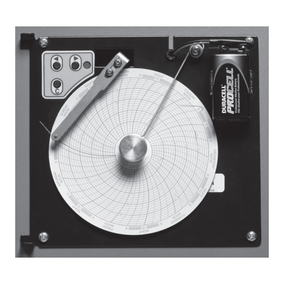
Touring the Chart Recorder 2 .2 Touring the chart recorder assembly This section describes parts common to both installed and standalone configurations. 2 .2 .1 Touring the front Front of chart recorder with chart paper and battery installed Label Description Function Left and Right Arrow buttons Used to adjust settings and the stylus position LED (light-emitting diode) Indicates the status of the chart recorder while in operating mode, or the selected temperature range value in paper... - Page 8 Touring the Chart Recorder 2 .2 .2 Touring the rear NOTE For more information about connectors on the circuit board, see Section 8.2, “Schematics.” Rear of chart recorder Label Description Function Stylus (pin) motor Moves the stylus Paper motor Rotates the paper Circuit board Controls chart recorder operation 360076-1/K...
-
Page 9: Installing The Chart Recorder
Installing the Chart Recorder Installing the chart recorder 3.1 Recording identification information For easy reference, write the serial number on the front of this manual. The serial number is needed to provide efficient service. For chart recorders are installed on Helmer products, the serial number can be found on the product’s Product Specification label. - Page 10 Installing the Chart Recorder 3 .3 .1 Placing the chart recorder on a horizontal surface The rubber feet on the stand prevent the surface from being scratched, and the adjustment knob allows you to adjust the viewing angle. Chart recorder with stand, tilted for viewing 3 .3 .1 .1 Adjusting the viewing angle You may adjust the viewing angle.
- Page 11 Installing the Chart Recorder 3 .3 .2 .2 Mounting the chart recorder on a wall The chart recorder has two rear apertures that allow it to be mounted on a wall. Left: Mounting holes on the chart recorder. Right: Chart recorder mounted on a wall. To mount the chart recorder on a wall Remove the stand from the chart recorder.
- Page 12 Installing the Chart Recorder To mount the chart recorder under a cabinet Remove the stand from the chart recorder. For instructions, see Section 3.3.2.1, “Removing the stand.” Attach the stand to the bottom of the cabinet With the bottom of the stand facing up, and the adjustment slot on the left side, mark the underside of the cabinet with the location for the four mounting screws.
-
Page 13: Connecting To And Disconnecting From Power
Installing the Chart Recorder Install the adjustment knob by inserting it through the outer compression washer (black side toward the chart recorder), through the adjustment slot on the stand, and through the inner compression washer, then into the adjustment hole on the chart recorder. Tilt the chart recorder to the desired angle, then tighten the knob to hold it in place. -
Page 14: Configuring The Chart Recorder
Configuring the Chart Recorder Configuring the chart recorder This section includes procedures to configure the chart recorder prior to operation. 4 .1 Setting the temperature range for your application The chart recorder has three settings, each of which corresponds to a certain temperature range. For valid temperature information, the correct chart paper must be installed, and the temperature range must be set to the correct value. The options are as follows: Temperature range Helmer product... - Page 15 Configuring the Chart Recorder paper corresponds with the temperature range. Be sure to use the correct paper for your product or application. For part number information, see Section 7.2, “Parts.” After seven days of continuous recording, the paper must be changed. If the paper is not changed, the paper will continue to rotate, resulting in multiple temperature markings.
-
Page 16: Calibrating The Chart Recorder
Configuring the Chart Recorder 4 .3 Calibrating the chart recorder Calibrate to ensure the temperature being marked matches that read by the chart recorder probe. The frequency for calibration and the acceptable tolerance may be determined by your organization. The chart recorder should be calibrated whenever the temperature range is changed. Verify the probe is reading correctly by comparing the reading to that of an independent thermometer. -
Page 17: Understanding Normal Operation
Understanding Normal Operation Understanding normal operation This section describes how the chart recorder normally operates, and explains the meaning of the LED patterns for each mode. 5 .1 Understanding initialization When the chart recorder starts receiving power, it goes through an initialization sequence. First, the stylus travels outward until the stylus tip reaches near the outer edge of the chart paper. -
Page 18: Maintaining The Chart Recorder
Maintaining the Chart Recorder Maintaining the chart recorder 6 .1 Reviewing the preventive maintenance schedule Maintenance tasks must be completed according to the following schedule. NOTE These are minimum requirements. Regulations for your organization or physical conditions at your organization may require maintenance items to be performed more frequently. -
Page 19: Troubleshooting And Servicing The Chart Recorder
Troubleshooting and Servicing the Chart Recorder Troubleshooting and servicing the chart recorder This section explains issues you may experience while using the chart recorder, and provides actions you may take to correct them. This section also includes information about certain replacement parts. 7 .1 Troubleshooting CAUTION... - Page 20 Troubleshooting and Servicing the Chart Recorder Problem Possible cause Action The chart recorder paper The chart recorder is Verify the following and correct issues as is not rotating. not receiving power necessary. ► Verify the power cord is connected (standalone units only). securely to the chart recorder and the outlet.
- Page 21 Troubleshooting and Servicing the Chart Recorder 7 .1 .2 Troubleshooting visual indicators For more information, see Section 5.3, “Understanding visual indicators.” Problem Possible cause Action The LED is constant red. The backup battery is ► Verify a battery is installed and connected. missing or not connected.
- Page 22 Troubleshooting and Servicing the Chart Recorder Problem Possible cause Action The LED is flashing green. The chart recorder is ► Wait for the initialization process to end. initializing after start-up or For more information, see Section 5.1, restoration of power. “Understanding initialization.” The chart recorder is in ► Verify the temperature range is set paper change mode.
- Page 23 Troubleshooting and Servicing the Chart Recorder Problem Possible cause Action The stylus moves beyond The temperature range is ► Verify the temperature range is set correctly the outer edge of the set to the wrong range. for your application. For more information paper.
- Page 24 Troubleshooting and Servicing the Chart Recorder Problem Possible cause Action The temperature line The chart recorder probe In the product where the chart recorder is being marked is more is not immersed in the installed, do the following: ► Verify the chart recorder probe is immersed erratic, fuzzy, or saw- probe bottle.
- Page 25 Troubleshooting and Servicing the Chart Recorder 7 .1 .5 Removing the rear panel (standalone units only) Some tasks require you access the inside of the chart recorder. Use the following procedures to remove and replace the rear panel. You will need a screwdriver to remove the rear panel from the base. CAUTION Before removing the rear panel, disconnect the power to the chart recorder to eliminate the potential of electric shock.
-
Page 26: Parts
Troubleshooting and Servicing the Chart Recorder 7 .1 .7 Testing the probe circuit If you notice the LED is slowly flashing green, or temperature markings are slowly and repeatedly deviating from the calibrated temperature, then there may be a problem with the probe circuit. You may test the probe circuit to determine where the problem lies. When the chart recorder is put into probe simulation mode, a jumper is added to the probe circuit in place of the chart recorder probe. The jumper causes the circuit board to provide a fixed resistance that simulates a temperature reading. The stylus should move to a fixed temperature on the paper. - Page 27 Troubleshooting and Servicing the Chart Recorder 7 .2 .1 Cover and main power parts (standalone units only) Standalone chart recorder with various parts shown Label Description Replacement part numbers Label on schematic Probe 400799-1 Power connector with fuse Fuses are not included holder 115 V models: 120152 230 V models: 120379...
-
Page 28: Reference Information
Reference Information Reference information NOTE Information in this section is for the chart recorder. For information about the product in which the chart recorder is installed, refer to the Operation Manual for the product. 8.1 Technical specifications 8 .1 .1 Power 8 .1 .1 .1 Input voltage and frequency For chart recorders installed in a Helmer product, the main power varies depending on the product in... - Page 29 Reference Information This monitoring system is designed for indoor use only. Altitude (maximum): 2000 m Ambient temperature range: 5 ºC to 40 ºC (41 ºF to 104 ºF) Relative humidity (maximum for ambient temperature): 80% 8 .1 .5 Energy conservation and regulatory compliance This product is certified to applicable UL and CSA standards by a NRTL. Pollution Degree: 2 (for use in USA and Canada only) 8 .1 .5 .1 WEEE compliance The WEEE (waste electrical and electronic equipment) symbol indicates compliance with European Union Directive WEEE 2002/96/EC and applicable provisions.
-
Page 30: Schematics
Reference Information 8 .2 Schematics MAIN POWER 115 (±10%) V 50/60 Hz 230 (±10%) V 50/60 Hz 230 V models only PAPER PAPER 12 V Chart recorder schematics. Left: As installed in a Helmer product. Right: Standalone unit Label Description Stylus (pin) motor Paper (timer) motor Backup battery... -
Page 31: Warranty
Reference Information Warranty USA and Canada For technical service needs, please contact Helmer at 800-743-5637 or www.helmerinc.com. Be sure to have the model and serial number available. Rapid Resolution When a warranty issue arises it is our desire to respond quickly and appropriately. The service department at Helmer is there for you. Helmer will oversee the handling of your warranty service from start to finish. Therefore, Helmer must give advance authorization for all service calls and/or parts needs relating to a warranty issue. - Page 32 HELMER SCIENTIFIC 14400 Bergen Boulevard Noblesville, IN 46060 USA PH +1.317.773.9073 FAX +1.317.773.9082 www.helmerinc.com...
Need help?
Do you have a question about the TCR and is the answer not in the manual?
Questions and answers