
Related Manuals for Dini Argeo DGT4X


Summary of Contents for Dini Argeo DGT4X
- Page 1 DGT4X Digital weight Transmitter with 4 channels QUICK START GUIDE V1 ENGLISH www.diniargeo.com...
-
Page 2: Electrical Scheme
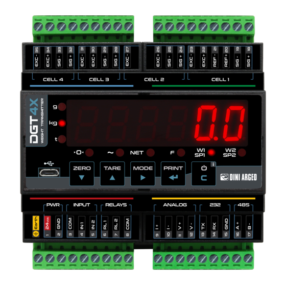
1. Electrical scheme In LOAD CELL 2, 3, 4 connect: There’s a single SENSE circuit that Load cells exitation: 5 V. SEN + to EXC + compensate all 4 load cells. Load cells output: 6 mV/V max. SEN - to EXC - 35 34 33 32 31 30... - Page 3 2. Key function in configuration menu and in weighing mode CELL 4 CELL 3 CELL 2 CELL 1 ZERO TARE MODE PRINT INPUT RELA YS ANALOG Configuration menu Weighing mode Decreases digit / Scroll down. Clears the displayed gross weight. Increases digit / Scroll up.
-
Page 4: Configuration Menu
4. Configuration menu 1. Reboot the weight transmitter 2. Press the key when display shows the message: 888888 888888 TYPE nChan Functioning mode (ch. 5). Chan div.deC Scale configuration: capacity, resolution and decimal point (ch. 6). CapaC Cel.Cap Cel.sen Theoretical calibration (ch. 7). dead.ld Zeroing of the deal load (pre-tare zeroing) (ch. -
Page 5: Functioning Mode
5. Functioning mode Digital equalisation box mode. 888888 TYPE dep.Ch ind.Ch Multi-scale mode. Set the number of active channels. nChan CHAN Select the channel to be programmed (for ind,Ch mode only). MODE 1 “DEP.CH” Allows to connect directly the load cells, equalize them (if necessary) and transmit each load cell data and the total weight through Fieldbus. Load cell 1 Load cell 2 Type... -
Page 6: Theoretical Calibration
6. Maximum scale capacity, increment and decimal point setting 888888 div.deC Set the decimal point position and the minimum scale increment* div.deC 0,001 0,002 0,005 0,01 0,02 0,05 Set the maximum scale capacity* (max div.deC CapaC 999999 Examples: For a 60000 kg scale, with 2 kg For a 10000 g scale, with 0,1 g increment: For a 3000 kg scale, with 0,05 kg increment:... - Page 7 8. Zeroing of the mechanic tare (pre-tare zeroing) 888888 div.deC div.deC 0.Calib Zeroing of the pre-tare (or mechanical tare). This functionality allows to zero the weigh of the scale structure (e.g. empty silo, conveyor, etc.) without changing the calibration in memory.
-
Page 8: Input Setting
11. Input setting 888888 div.deC inps div.deC inp.01 INP.02 inp.02 none Input disabled. dis.key When input is active, transmitter keyboard is locked. When input is active, transmitter reboots. Emulation of key. Emulation of key. prin mode Emulation of key. Emulation of key. - Page 9 13. RS485 port 888888 div.deC 485 address (01 ÷ 98). div.deC se.add Baud rate (1200, 2400, 4800, 9600, 19200, 38400, 57600, 115200). bad The RS485 port is configured by default to communicate in Modbus RTU (ch. 18). 14. Broken laod cell exclusion (for dependent channels systems) If a load cell is broken, it’s possible to temporarely exclude the channel where it is connected and continue to weigh, pending replacement.
-
Page 10: Programming Errors
15. Programming errors MESSAGE DESCRIPTION SOLUTION First calibrate the zero point (zero), then proceed with the preC. Calibration error sample weight acquisition (span) (ch. 9). Check the connection of the load cell. Check that the cell Err.pn Calibration error signal is stable, valid and greater than that of the previously acquired point. - Page 11 16. Modbus 16.1 MODBUS REGISTERS - dep.CH / ind.ch (1 SCALE) Data Register DESCRIPTION 30001 Gross weight Gross Weight value. 30002 30003 Net weight Net Weight value. 30004 Bit 15 Active channel. (msb) Bit 15 Bit 14 Active Channel Bit 14 Active channel.
- Page 12 16.2 MODBUS REGISTERS - ind.ch (4 SCALES) Data Data Register Register DESCRIPTION DESCRIPTION Bit 15 Bit 15 (msb) (msb) No function. No function. Bit 8 Bit 8 (lsb) (lsb) Bit 7 Bit 7 Tare PT (1 = PT tare is active). Tare PT (1 = PT tare is active).
- Page 13 16.3 MODBUS REGISTERS FOR COMMAND SENDING Data Register DESCRIPTION Main available commands: Value Command 00 Hex No command 01 Hex Scale zeroing 02 Hex Tare Command 40001 03 Hex Preset Tare 0A Hex Setpoint 1 setting 0B Hex Setpoint 2 setting 19 Hex Digital output setting 22 Hex...
- Page 14 Notes This publication, or portions thereof, may not be duplicated without written permission from the Manufacturer. All information contained in this manual is based on the data available at the time of its publication; the Manufacturer reserves the right to make changes to its products at any time without notice and without incurring any penalty.
-
Page 16: Service Assistance
HEAD OFFICE Authorized service center stamp Via Della Fisica, 20 41042 Spezzano di Fiorano, Modena - Italy Tel. +39 0536 843418 - Fax +39 0536 843521 SERVICE ASSISTANCE Via Dell’Elettronica, 15 41042 Spezzano di Fiorano, Modena - Italy Tel. +39 0536 921784 - Fax +39 0536 926654 www.diniargeo.com...
Need help?
Do you have a question about the DGT4X and is the answer not in the manual?
Questions and answers