Table of Contents
Advertisement
Quick Links
Advertisement
Table of Contents

Related Manuals for YOKOGAWA 702915


Summary of Contents for YOKOGAWA 702915
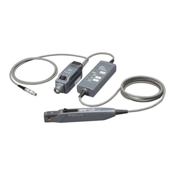
- Page 1 User's Model 702915/702916 Manual Current Probe IM 702915-01EN 1st Edition...
- Page 2 Product Registration Thank you for purchasing YOKOGAWA products. YOKOGAWA provides registered users with a variety of information and services. Please allow us to serve you best by completing the product registration form accessible from our website. https://tmi.yokogawa.com/ PIM 103-04E_A5...
- Page 3 Thank you for purchasing the 702915/702916 Current Probe. This user’s manual explains the features, operating procedures, and handling precautions of the 702915/702916 Current Probe. To ensure correct use, please read this manual thoroughly before beginning operation. After reading this manual, keep it in a safe place.
-
Page 4: Checking The Package Contents
The following items are included. If the wrong items have been delivered, if items are missing, or if there is a problem with the appearance of the items, contact your nearest YOKOGAWA dealer. • 702915 or 702916: 1 (see figure below) •... -
Page 5: Safety Precautions
If the instrument is used in a manner not specified in this manual, the protection provided by the instrument may be impaired. YOKOGAWA assumes no liability for the customer’s failure to comply with these requirements. -
Page 6: Notes About Usage
• Refer to the precautions (warnings) regarding electric shock and other safety matters of the devices to be connected, and use the devices carefully. • Do not let the instrument get wet or operate it with wet hands. Doing so may cause electric shock. IM 702915-01EN... - Page 7 • In a strong magnetic field or near objects charged with static electricity. • Near a high frequency dielectric heating device, IH cookware, or other dielectric heating equipment. • In an environment subject to large levels of mechanical vibration. • Near high frequency power equipment. IM 702915-01EN...
- Page 8 électrique et d'autres points de sécurité des appareils à raccorder et utilisez les appareils avec précaution. • Évitez que l'équipement ne soit mouillé et ne le manipulez pas avec des mains humides. Ceci risquerait d'entraîner un choc électrique. IM 702915-01EN...
- Page 9 • Dans un champ magnétique puissant ou à proximité d'objets chargés d'électricité statique . • À proximité d'un radiateur diélectrique à haute fréquence, d'articles culinaires IH ou d'un équipement de chauffage diélectrique • Dans un environnement soumis à des niveaux élevés de vibrations mécaniques IM 702915-01EN...
- Page 10 If damage is detected, contact your nearest YOKOGAWA dealer. • The sensor head is an intricately assembled component made of a molded part, ferrite core, Hall effect element, and so on.
- Page 11 • To prevent damaging this instrument’s output terminal when you remove this instrument from the waveform measuring instrument, pull the lock release lever completely toward you, and then remove it. IM 702915-01EN...
- Page 12 • The overload warning may not work when current outside the overload detection frequency range is measured. Regardless of whether the OVERLOAD LED is blinking, be careful not to exceed the maximum rated current. IM 702915-01EN...
- Page 13 à cause du stockage, du transport et d'autres opérations. Si un endommagement est détecté, contactez votre distributeur YOKOGAWA le plus proche. • La tête du capteur est un composant assemblé de manière complexe et composé d'une pièce moulée, d'un noyau de ferrite, d'un élément d'effet Hall etc.
- Page 14 L'équipement risquerait de tomber ou de rouler et d'entraîner des blessures ou encore de s'endommager. • Ne faites pas pivoter le terminateur de cet équipement lorsqu'il est raccordé à l'équipement de mesure de la forme d'onde. Ceci risquerait d'endommager le terminateur ou la IM 702915-01EN...
- Page 15 à l'intensité nominale maximale, risque d'entraîner une importante augmentation de la température. Opérez avec précaution, ceci risque d'endommager la tête du capteur. • Même si l'intensité du courant est inférieure à l'intensité nominale maximale, la surchauffe automatique risque d'endommager l'équipement. IM 702915-01EN...
- Page 16 • Accurate measurements may not be possible near objects with strong electromagnetic fields such as transformers, large current circuits, and wireless equipment. • Depending on the current frequency that is measured, oscillation may occur, but this has no effect on measurements. IM 702915-01EN...
-
Page 17: Waste Electrical And Electronic Equipment
Authorized Representative in the EEA Yokogawa Europe B. V. shall act as Authorized Representative of Yokogawa Test & Measurement Corporation in the EEA for this Product. To contact Yokogawa Europe B. V., see the separate list of worldwide contacts, PIM 113-01Z2. Disposal When disposing of this product, follow the laws and ordinances of your country or region. -
Page 18: The Notes And Cautions In This Manual Are Categorized Using The Following Symbols
ATTENTION Attire l’attention sur des gestes ou des conditions susceptibles de provoquer des blessures légères ou d’endommager l’instrument ou les données de l’utilisateur, et sur les précautions de sécurité susceptibles de prévenir de tels accidents. IM 702915-01EN... -
Page 19: Table Of Contents
4. Product Specifications ............. 37 Electrical Specifications ..............37 General Specifications ................ 38 External Dimensions ................39 5. Typical Characteristics ............. 40 6. Troubleshooting ............... 46 Before Sending the Instrument for Repair ........... 46 Types of Errors and Corrective Actions ..........47 IM 702915-01EN... -
Page 20: Product Overview
1. Product Overview Model 702915 and Model 702916 Current Probes are clamp-on current probes that feature high current-detection sensitivity and broad frequency band. Both probes use three (3) current ranges to detect a variety of current waveforms from 1 mA to 30 Arms with a single unit. -
Page 21: Configuration And Functions
Termination Unit Output Terminal Lock Release Lever Opening Lever Sensor Aperture Sensor Unit Sensor Head Power Plug Power Cable Shell Junction Box POWER OVERLOAD JAW UNLOCKED DEMAG / AUTO ZERO Key DEMAG / AUTO ZERO RANGE Range Key IM 702915-01EN... -
Page 22: Component Functions
The demagnetization function cancels the magnetization of the magnetic core caused by power ON/OFF or excessive input. The auto- zero function corrects unnecessary effects such as offset voltage and temperature drift of the instrument. Following demagnetization, it is automatically zero-adjusted. IM 702915-01EN... - Page 23 30 A range: 32.5 ±2.5 Arms 5 A range: 5.25 ±0.25 Arms 0.5 A range: 0.525 ±0.025 Arms The sampling frequency for overload detection is 7.8125 kHz (typical), and the checking cycle is 500 ms (typical). IM 702915-01EN...
-
Page 24: Led Display Functions
Solid Demag/auto-zero in progress. Demag/auto-zero performed. Blinks 3 times Demag/auto-zero error occurred. Blinks rapidly Switched to protection mode. Checksum error occurred. RANGE (green) Solid Indicates the set current range. Blinks rapidly Switched to protection mode. Checksum error occurred. IM 702915-01EN... -
Page 25: Operation Procedure
• Faites attention de ne pas endommager le cache d'isolation du conducteur. • Ne pas court-circuiter entre les deux lignes de mesure avec la partie métallique du capteur. Cela peut entraîner un accident grave tel que l'apparition d'un arc. IM 702915-01EN... -
Page 26: Measurement Preparation
• When a 702915/702916 current probe is used, depending on the measured current, it may not be possible to use multiple active probes with the 701934 probe power supply or the probe power supply from a YOKOGAWA waveform measuring instrument. - Page 27 3. Operation Procedure • Si une sonde de courant 702915/702916 est utilisée, suivant l'intensité mesurée, vous risquez de ne pas pouvoir utiliser plusieurs sondes actives avec l'alimentation de la sonde 7001934 ou l'alimentation de sonde d'un équipement de mesure de la forme d'onde YOKOGAWA.
- Page 28 Correct measurement is not possible with an input impedance of 50 Ω. • The offset drift may be large immediately after starting to supply power due to instrument’s self-heating and other effects. To make accurate measurements, warm up for at least 30 minutes. IM 702915-01EN...
-
Page 29: Demagnetization And Zero Adjustment
For the same reason, make sure that the conductor is not clamped when supplying power to the 702915/702916. A demagnetization waveform may be generated when power is supplied. IM 702915-01EN... - Page 30 à mesurer. Pour la même raison, assurez-vous que le conducteur n'est pas serré lors de l'alimentation en courant de 702915/702916. Une forme d'onde de démagnétisation peut être générée lors d'une alimentation en courant. Be sure to perform demagnetization and zero adjustment before making measurements.
- Page 31 To Perform Only Zero Adjustment To perform only zero adjustment (without demagnetization), press DEMAG/AUTO ZERO for a short time in step 4 on the previous page. The DEMAG/AUTO ZERO LED turns on. When zero adjustment is complete, the LED turns off. IM 702915-01EN...
-
Page 32: Measurement Method
Use the probe in a way that the rms value does not exceed the continuous maximum input range. • Be sure to use the opening lever to open the upper jaw. Pressing the top core when the upper jaw is locked will damage the clamping mechanism. IM 702915-01EN... - Page 33 à des intensités comprises dans la plage d'entrée continue maximale. • Si un courant dépassant la plage d'entrée continue maximale est appliqué en continu ou si la fonction de protection est régulièrement activée, l'équipement risque de se casser. IM 702915-01EN...
- Page 34 Low potential side (ground potential side) High potential side Hold down the sensor opening lever until the JAW UNLOCKED indication disappears to lock the upper jaw. The JAW UNLOCKED LED turns off. IM 702915-01EN...
- Page 35 (0.5 A, 5 A, or 30 A). The current waveform can be observed on the waveform measuring instrument. The output voltage rate of the 702915 and 702916 is 10 V/ A (0.5 A range), 1 V/A (5 A range), or 0.1 V/A (30 A range), depending on the current range selected.
- Page 36 If the conductor is wound 10 times, the probe will output 10 times the measured current. However, wind the conductor radially at a diameter of at least 20 cm. Wind radially At least φ20 cm IM 702915-01EN...
-
Page 37: Ending Measurement
• Hold the power plug shell and remove. • Do not pull the cable or rotate the power plug. (Pulling the power plug shell releases the lock allowing you to remove it from the power supply receptacle.) IM 702915-01EN... - Page 38 Turn off the waveform measuring instrument with a probe power supply or the 701934 power supply. Remove the instrument’s power plug. Hold the power plug shell and remove. Do not pull the cable or rotate the power plug. IM 702915-01EN...
-
Page 39: Product Specifications
3 "Typical" values are typical or average values and are not strictly guaranteed. 4 Specified by DC and sine wave. Depending on the ambient temperature or measurement conditions, the internal temperature may increase and these values may decrease. IM 702915-01EN... -
Page 40: General Specifications
EN50581 (RoHS directive) Monitoring and control instruments 1 Power is supplied from the probe power terminals on Yokogawa's oscilloscope or Probe Power Supply Unit (model 701934 , sold separately). 2 See "Consumption Current" in "Typical Characteristics" for details. IM 702915-01EN... -
Page 41: External Dimensions
4. Product Specifications External Dimensions Unit: mm Sensor Unit Cable Length 1500 702915 Junction Box Cable Length Power Cable Length Termination Unit 1000 Sensor Unit IM 702915-01EN... -
Page 42: Typical Characteristics
5. Typical Characteristics All of the characteristics shown in this section are typical. The values shown here are not strictly guaranteed. Frequency Characteristics 702915 (50MHz) Frequency Response 0.5 A range 5 A range 30 A range 10 k 100 k... - Page 43 5. Typical Characteristics Frequency Derating 702915 (50MHz) Frequency Derating 30 A range 5 A range 10 k 100 k 10 M 100 M 1000 M Frequency [Hz] 702916 (120MHz) Frequency Derating 30 A range 5 A range 10 k 100 k...
- Page 44 5. Typical Characteristics Input Impedance 702915 (50MHz) Input Impedance 0.01 0.001 10 k 100 k 10 M 100 M Frequency [Hz] 702916 (120MHz) Input Impedance 0.01 0.001 10 k 100 k 10 M 100 M 1000 M Frequency [Hz] IM 702915-01EN...
- Page 45 - Power Supply DC Consumption Current (5 A range) +Power Supply DC +Power Supply AC (50Hz) -Power Supply DC -100 -Power Supply AC (50Hz) -150 -200 -250 -7.5 - Power Supply DC -6.0 -4.5 -3.0 -1.5 Measured Current [A] IM 702915-01EN...
- Page 46 +Power Supply DC +Power Supply AC (50Hz) -Power Supply DC -Power Supply AC (50Hz) -200 Measured Current [A] - Power Supply DC Influence of Common-Mode Voltage Influence of Common-mode Voltage (702915/702916) 0.5A range 5A range 30A range -100 -120 -140 -160...
- Page 47 Influence of Residual Magnetization (0.5 A range) -0.5 -0.3 -0.2 0.4 0.5 -0.4 -0.1 Input Current [A] Influence of Residual Magnetization (5 A range) Input Current [A] Influence of Residual Magnetization (30 A range) -15 -10 15 20 Input Current [A] IM 702915-01EN...
-
Page 48: Troubleshooting
6. Troubleshooting • If damage is suspected, check “Before Sending the Instrument for Repair” before contacting your nearest YOKOGAWA dealer. • If no waveform is displayed even after performing demagnetization and zero adjustment, the instrument may be damaged. Contact your nearest YOKOGAWA dealer. -
Page 49: Types Of Errors And Corrective Actions
Junction box drops. If pressing any key on the junction box, it will return to the normal state, so demag/auto-zero adjustment will be executed again. In addition, it is recommended to calibrate the instrument because the internal parts may be stressed by heat. IM 702915-01EN... - Page 50 Also, immediately after switching the current range, overload may not be detected correctly. The OVERLOAD LED may blink due to the influence of an external magnetic field when the jaws are open, but this is not a malfunction. IM 702915-01EN...
- Page 51 Jaw locked state. 0.50 ± 0.25 Arms (DC, 45 to 66 Hz sine waves) Take any of the following actions, depending on the status after the LEDs blink 3 times. After that, demagnetizing and automatic zero-adjustment will be performed again. IM 702915-01EN...
- Page 52 Lights in green POWER Turns off OVERLOAD Lights in red or turns off JAW UNLOCKED Remove the sensor from the conductor to be measured. Then press the opening lever until the JAW UNLOCKED indicator disappears to lock the jaw. IM 702915-01EN...
- Page 53 10V/A There is something wrong with the internal CPU. Please request repair. Malfunction All LEDs turn off POWER OVERLOAD JAW UNLOCKED DEMAG AUTO ZERO RANGE 0.1V/A 1V/A 0.5A 10V/A The instrument is out of order. Please request repair. IM 702915-01EN...
Need help?
Do you have a question about the 702915 and is the answer not in the manual?
Questions and answers