
Subscribe to Our Youtube Channel
Related Manuals for Riello G 24


Summary of Contents for Riello G 24
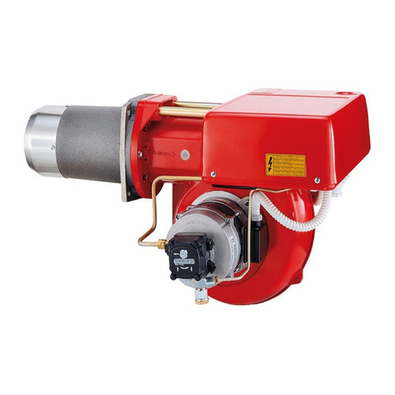
- Page 1 Installation, use and maintenance instructions Light oil burner Two-stage operation G 24 CODE MODEL TYPE 3473000 G 24 651 M 2915388 (5) - 10/2013...
- Page 2 The quality is guaranteed by a quality and management system certified in accordance with UNI EN ISO 9001. Legnago, 19.11.2012 Executive Director Research & Development Director RIELLO S.p.A. - Burner Department RIELLO S.p.A. - Burner Department Mr. I. Zinna Mr. R. Cattaneo...
-
Page 3: Table Of Contents
CONTENTS BURNER DESCRIPTION ..............2 1.1 Standard equipment . -
Page 4: Technical Data
2. TECHNICAL DATA MODEL G 24 TYPE 651 M THERMAL POWER 140 ÷ 237 kW / 120.000 ÷ 240.000 kcal/h OUTPUT 12 ÷ 24 kg/h FUEL Gas oil, max. viscosity at 20 °C: 6 mm /s (1.5 °E) ELECTRICAL SUPPLY... -
Page 5: Hydraulic Systems
3. HYDRAULIC SYSTEMS GRAVITY FEED from the bottom of the oil storage tank L meters øi øi meters 8 mm 10 mm The dimension P should not exceed 10 m, to avoid breakage of pump seals. GRAVITY FEED over the top of the oil storage tank L meters øi øi... -
Page 6: Electrical System
4. ELECTRICAL SYSTEM 4.1 ELECTRICAL SYSTEM FACTORY-SET KEY TO LAYOUT - Capacitor FR - Photoresistance MB - Burner terminal strip MV - Motor TA - Ignition transformer TB - Burner ground (earth) connection V1 - 1st stage solenoid valve V2 - 2nd stage solenoid valve S8981 4.2 ELECTRICAL CONNECTION TO THE TERMINAL STRIP... -
Page 7: Burner Adjustment
5. BURNER ADJUSTMENT Establish, on the basis of the output desired, and in accordance with the table and the diagram underneath: - the type of nozzle; - the pump pressure; - the combustion head setting. EXAMPLE The burner has to be matched with a boiler of 220 kW. Assuming an efficiency of 90%, we need to develop approximately 245 kW i.e. -
Page 8: Air Damper Adjustment
5.2 AIR DAMPER ADJUSTMENT Fig. 4 Adjusting the air delivery effected on the air damper 1 (Fig. 4) after loosening screws 2 and 3. Once the air damper has been adjusted, tighten 2 and 3 fully down. 5.3 POSITIONING OF ELECTRODES Fig. -
Page 9: Priming The Pump
6. PRIMING THE PUMP In case of a gravity feed system, from the bottom of the oil-storage tank (see page 4), loosen the screw of the suction-gauge fixing point 3 (Fig. 1), until the fuel flows out. In the other two cases, start the burner and bleed the air from the pressure gauge connection by loosening plug 4 (Fig. - Page 12 RIELLO S.p.A. I-37045 Legnago (VR) Tel.: +39.0442.630111 http:// www.riello.it http:// www.rielloburners.com Subject to modifications...
Need help?
Do you have a question about the G 24 and is the answer not in the manual?
Questions and answers