Viessmann VITORONDENS 200-T Service Instructions Manual
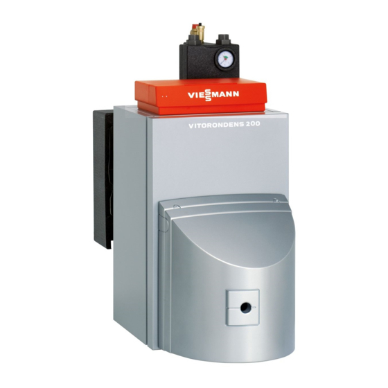
Oil unit condensing boiler
Hide thumbs
Also See for VITORONDENS 200-T:
- Service instructions manual (32 pages) ,
- Installation instructions manual (28 pages) ,
- Technical manual (52 pages)

Related Manuals for Viessmann VITORONDENS 200-T


Summary of Contents for Viessmann VITORONDENS 200-T
- Page 1 VIESMANN Service instructions for contractors Vitorondens 200-T Type BR2A, 20.2 to 53.7 kW Oil Unit condensing boiler VITORONDENS 200-T Please keep safe. 5624309 GB 7/2019...
-
Page 2: Safety Instructions
Safety instructions Safety instructions Please follow these safety instruc- tions closely to prevent accidents and material losses. Safety instructions explained Danger Note This symbol warns against the risk Details identified by the word "Note" of injury. contain additional information. Please note This symbol warns against the risk of material losses and environmen- tal pollution. -
Page 3: Auxiliary Components, Spare And Wearing Parts
Viessmann. water pipes to discharge static loads. Repair work Please note Repairing components that fulfil a safety function can compromise the safe operation of the system. Replace faulty components only with genuine Viessmann spare parts. - Page 4 Safety instructions Safety instructions (cont.) Safety instructions for operating the system If you smell gas Condensate Danger Danger Escaping gas can lead to explo- Contact with condensate can be sions which may result in serious harmful to health. injury. Never let condensate touch your Do not smoke.
- Page 5 Safety instructions Safety instructions (cont.) Danger The simultaneous operation of the boiler and appliances that exhausts air to the outside can result in life threatening poisoning due to a reverse flow of flue gas. Fit an interlock circuit or take suita- ble steps to ensure an adequate supply of combustion air.
- Page 6 Index Index Information Symbols ....................Intended use ..................Spare parts lists ..................Commissioning, inspec- Steps - commissioning, inspection and maintenance ......tion, maintenance Commissioning/service ........................ 19 reports Specification ........................ 20 Shutdown and disposal Final decommissioning and disposal ............. 21 Certificates Declaration of conformity ...............
-
Page 7: Intended Use
Information Symbols The steps in connection with commissioning, inspec- Symbol Meaning tion and maintenance are found in the "Commission- Reference to other document containing ing, inspection and maintenance" section and identified further information as follows: Step in a diagram: Symbol Meaning The numbers correspond to the order in Steps required during commissioning... - Page 8 Information Spare parts lists Information about spare parts can be found on the Viessmann spare parts app.
- Page 9 Commissioning, inspection, maintenance Steps - commissioning, inspection and maintenance Commissioning steps Inspection steps Maintenance steps Page • 1. Filling the heating system....................10 • 2. Venting the boiler at the safety equipment block (accessories)........11 • 3. Venting the heating system •...
- Page 10 Commissioning, inspection, maintenance Filling the heating system Fill water According to EN 1717 with DIN 1988-100, as a heat Please note transfer medium for DHW heating, the heating water Unsuitable fill water increases the level of must meet fluid category ≤ 3. This requirement is met if deposits and corrosion and may lead to appli- water of potable quality is used as heating water.
- Page 11 Commissioning, inspection, maintenance Filling the heating system (cont.) With safety equipment block (accessories) 1. Check the pre-charge pressure of the expansion vessel. 2. Close the bypass valve on the boiler flow/return distributor. 3. Remove front insulation shell 4. Open air vent valve 5.
-
Page 12: Draining The Heating System (If Required)
Commissioning, inspection, maintenance Draining the heating system (if required) Fig. 4 Drain Opening the boiler door Fig. 5 For room sealed operation: Remove the ventilation air pipe before opening the boiler door. -
Page 13: Cleaning The Heating Surfaces
Commissioning, inspection, maintenance Cleaning the heating surfaces Boiler heating surface Fig. 6 Cleaning brush (accessories) 1. Clean the combustion chamber and the boiler Cleaning agent manufacturer's instructions heating surfaces with a cleaning brush and vac- uum cleaner. 2. Remove soot deposits with alkaline agents con- taining surfactant additives (e.g. -
Page 14: Fitting The Boiler Door
Commissioning, inspection, maintenance Cleaning the heating surfaces (cont.) For stubborn residues, surface stains or soot deposits, For this, observe the following: cleaning agents can be used. ■ Only use solvent-free cleaning agents. ■ Remove soot deposits with alkaline agents contain- ing surfactant additives (e.g. -
Page 15: Checking The Neutralising System (If Installed)
Commissioning, inspection, maintenance Separating the neutralising system or active charcoal filter (if installed) from the boiler and connecting the drain hose Fig. 9 1. Separate hose to the neutralising system from 2. Connect drain hose to the condensate drain of trap the trap and run to a drainage system. - Page 16 Commissioning, inspection, maintenance Checking the connection on the flue gas side for leaks Fig. 10 Note 2. Check the heat exchanger fixings are firmly Traces of condensate indicate a leak. seated. 1. Remove thermal insulation strip and pull ther- 3. Check the connector on the heat exchanger for mal insulation mat out a little.
- Page 17 Commissioning, inspection, maintenance Filling the trap and neutralising system… (cont.) Remove the supply hose (to the trap) from the boiler condensate drain and fill with a little water. Checking connections on the heating water and DHW sides and the sensor well for leaks Checking the function of the safety equipment Checking the expansion vessel and system pressure...
-
Page 18: Checking The Ventilation Air Connection To The Burner (If Installed)
Commissioning, inspection, maintenance Checking the mixer for ease of operation and… (cont.) 3. Click the motorised lever into place. Checking the ventilation air connection to the burner (if installed) For room sealed operation: Check the ventilation air connection for damage. Adjusting the burner Burner service instructions Instructing the system user... -
Page 19: Commissioning/Service Reports
Commissioning/service reports Commissioning/service reports Commissioning Maintenance/service Maintenance/service Date: Maintenance/service Maintenance/service Maintenance/service Date: Maintenance/service Maintenance/service Maintenance/service Date: Maintenance/service Maintenance/service Maintenance/service Date: Maintenance/service Maintenance/service Maintenance/service Date:... -
Page 20: Power Consumption
Specification Specification Rated heating output = 50/30 °C 20.2 24.6 28.6 35.4 42.8 53.7 = 80/60 °C 18.8 22.9 27.0 33.0 40.0 50.0 CE designation CE-2456 CL 102 Power consumption 100 % of rated heating output ■ 30 % of rated heating output ■... -
Page 21: Final Decommissioning And Disposal
Shutdown and disposal Final decommissioning and disposal Viessmann products can be recycled. Components For decommissioning the system, isolate the system and substances from the system are not part of ordi- from the power supply and allow components to cool nary household waste. -
Page 22: Manufacturer's Certificate According To The 1St Bimschv [Germany]
This product meets the requirements of the Efficiency Directive (92/42/EEC) for condensing boilers. Manufacturer's certificate according to the 1st BImSchV [Germany] We, Viessmann Werke GmbH & Co. KG, D-35107 Allendorf, confirm that the following product meets the NO limits specified by the 1st BImSchV Paragraph 6:... - Page 23 Keyword index Keyword index Boiler, venting.............11 Intended use..............7 Boiler door – Fitting..............14 – Opening..............12 Neutralising system............15 Checking the active charcoal filter......15 Room sealed operation........12, 14, 18 Cleaning the heating surfaces........13 Commissioning............10 Connection on the flue gas side.........16 Shutdown..............
- Page 24 Viessmann Werke GmbH & Co. KG Viessmann Limited D-35107 Allendorf Hortonwood 30, Telford Telephone: +49 6452 70-0 Shropshire, TF1 7YP, GB Fax: +49 6452 70-2780 Telephone: +44 1952 675000 www.viessmann.com Fax: +44 1952 675040 E-mail: info-uk@viessmann.com...
Need help?
Do you have a question about the VITORONDENS 200-T and is the answer not in the manual?
Questions and answers