
Related Manuals for Viessmann Vitorond 200 Series


Summary of Contents for Viessmann Vitorond 200 Series
-
Page 1: Installation Instructions
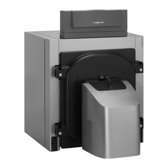
VIESMANN Installation instructions for contractors Vitorond 200 Type VD2A, 125 to 270 kW Oil/gas boiler VITOROND 200 Dispose after installation. 5592831 GB 9/2018... -
Page 2: Safety Instructions
Safety instructions Please follow these safety instructions closely to prevent accidents and material losses. Safety instructions explained Danger Note This symbol warns against the risk of injury. Details identified by the word "Note" contain additional information. Please note This symbol warns against the risk of material losses and environmental pollution. -
Page 3: Table Of Contents
Index Information Disposal of packaging ................Symbols ....................Intended use ..................Product information ................System examples .................. Preparing for installation Clearance dimensions ................Standard delivery, standard boiler ............Installation sequence Boiler section assembly ................. Preparing the back section ..............■ Fitting the first centre section and pressing the sections together .. -
Page 4: Information Disposal Of Packaging
Please dispose of packaging waste in line with statu- DE: Use the disposal system organised by tory regulations. Viessmann. AT: Use the ARA statutory disposal system (Altstoff Recycling Austria AG, licence number 5766). CH: Packaging waste is disposed of by the HVAC contractor. -
Page 5: Product Information
Product information Vitorond 200, type VD2A ■ Fuels: Fuel oil and natural gas Rated heating output 125 to 270 kW ■ Permissible operating pressure 6 bar (0.6 MPa) ■ System examples Available system examples: See www.viessmann- schemes.com. -
Page 6: Preparing For Installation Clearance Dimensions
Clearance dimensions 500 (200) 500 (200) 200 (100) Fig. 1 Outer edge, plinth (accessories) Dimensions in brackets are minimum clearances. Rated heating output 1200 1400 1600 1800 2000 Observe the installed burner length. -
Page 7: Standard Delivery, Standard Boiler
Standard delivery, standard boiler Fig. 2 Burner plate, supplied Back section Boiler door Flue outlet (fitted) Front section Boiler accessories can be found in the combustion Turbulators in the 2nd flues (only up to 195 kW) chamber. When delivered as a pre-assembled Anchor rods boiler block, there is no "pack of individual sec- Centre section (for number see table) -
Page 8: Installation Sequence Boiler Section Assembly
Boiler section assembly Note If the boiler is supplied as a pre-assembled block: Remove the boiler accessories from the combustion chamber. To continue, see page 16. 125-195 kW Fig. 3 Note We recommend siting the boiler on the plinth (acces- sories) with adjustable anti-vibration feet. -
Page 9: Preparing The Back Section
Boiler section assembly (cont.) Preparing the back section Fig. 4 Cleaning agent Observe clearance from the wall. See page 6. Fig. 5 Cleaning agent Linseed oil graphite, supplied Note The connectors must be seated straight and securely in the hubs. -
Page 10: Fitting The First Centre Section And Pressing The Sections Together
Boiler section assembly (cont.) Fitting the first centre section and pressing the sections together Applying sealant to sealing contour on 1st centre section Fig. 6 Sealing contour on 1st centre section Sealant supplied Pressing the sections together Handling the compression tool: Danger Compression tool installation instructions Escaping flue gas leads to breathing difficulties... - Page 11 Boiler section assembly (cont.) Fig. 7 When assembling the boiler sections, observe the fol- Removing the compression tool lowing ■ Keep the distance between the sections the same at Note the top and the bottom. Release and remove the compression tool before fit- Never secure the sections out of true.
-
Page 12: Fitting Further Boiler Sections And Pressing Them Together
Boiler section assembly (cont.) Fitting further boiler sections and pressing them together Fig. 8 Cleaning agent Linseed oil graphite, supplied Note The connectors must be seated straight and securely in the hubs. - Page 13 Boiler section assembly (cont.) Applying sealant to the sealing contour of all additional sections Fig. 9 Sealing contour on all additional sections Sealant supplied Pressing the sections together Danger Escaping flue gas leads to breathing difficulties See pages 10 to 11. and poisoning.
-
Page 14: Joining Sections With Anchor Rods
Boiler section assembly (cont.) Joining sections with anchor rods Fig. 10 Note Note The compression tool holds the boiler together. Only Only tighten nuts on anchor rods by hand. Never release the compression tool when the sections have apply force. been joined with anchor rods... -
Page 15: Removing The Compression Tool And Aligning The Boiler
Boiler section assembly (cont.) Removing the compression tool and aligning the boiler Fig. 11 Note All section feet must be firmly placed on the support surface. If required, shim the section feet. -
Page 16: Distributor Pipe And Drain Installation
Distributor pipe and drain installation Fig. 12 Gasket Quadrant for free-wheel ratchet, supplied with Distributor pipe compression tool Nuts Studs Plug R 2 Flange... - Page 17 Distributor pipe and drain installation (cont.) Fig. 13 Distributor pipe Reducer Sensor well Spacer Gasket Drain & fill valve (on site) Studs Boiler return gasket Ø 59 x 118 x 3 mm Note Check correct position of the distributor pipe.
-
Page 18: Checking The Boiler Block For Leaks
Checking the boiler block for leaks Only when delivered in individual sections Note Not required if the boiler is supplied as a single block (factory tested) Fig. 14 Blank flange (on site) Carry out water pressure test in accordance with TRD 702. -
Page 19: Turbulators (Only Up To 195 Kw) And Boiler Door
Turbulators (only up to 195 kW) and boiler door If the boiler is supplied in individual sections 125-195 kW Fig. 15 Note You may hang the boiler door for l.h. or r.h. opening. Torque for boiler door 30 Nm... -
Page 20: Connections On The Heating Water Side
Connections on the heating water side ≥400 Fig. 16 Drain, R 1 Drain & fill valve (on site) KR Boiler return, DN 65 Boiler return gasket Ø 59 x 118 x 3 mm KV Boiler flow, DN 65 Note Install all pipe connections free of load and torque stress. -
Page 21: Fitting The Thermal Insulation Mat
Fitting the thermal insulation mat Note All required components are included in the thermal insulation box. Fig. 17 Grub screws SW 17 Note Only tighten the grub screws by hand. In doing so, ensure that the back section is not tightened up. Level the grub screws if required. -
Page 22: Connections On The Flue Gas Side
Connections on the flue gas side Vitoair installation instructions 1. Connect the flue outlet with the shortest possible run to the chimney and maintain a slight incline. External Ø, flue outlet: 200 mm 2. Create a test port. 3. Seal in and insulate the flue pipe. Joints must be x Ø... -
Page 23: Fitting The Thermal Insulation Jacket
Fitting the thermal insulation jacket ≈80 Fig. 20 Black side outwards Cut-outs to the back Vitorond 200 logo... -
Page 24: Fitting The Panels
Fitting the panels Fitting the side panels and front panel Note Burner cables are supplied in the thermal lÖ insulation pack. 3.9 x 9.5 lÖ Fig. 21 Control unit and electrical connection Fitting the control unit and routing electrical cables/leads Note Boiler water temperature sensor is supplied in the... -
Page 25: Connections To The Control Unit Base
Control unit and electrical connection (cont.) § 6 x 12 Fig. 22 Screws, 6 x 12 (supplied with the control unit fas- LV leads cia) Burner cables 230 V cables Note Please note Route 230 V cables and LV leads separately. Never allow cables/leads to come into contact with hot components. -
Page 26: Fitting The Top Panels And Control Unit Fascia
Fitting the top panels and control unit fascia 3.9 x 9.5 Fig. 23 Type plate Boiler control unit installation instructions Mounting the burner Mounting and adjusting the burner: Burner documentation Boilers with 125 kW: Hole circle of burner fixing holes, burner fixing holes and flame tube aperture of supplied burner plate com- ply with EN 226. -
Page 27: Pressure Switch
Mounting the burner (cont.) ■ Max. flame tube aperture Ø 230 mm. Note Cut out the thermal insulation mat in the boiler door The flame tube must protrude at least 110 mm into the to suit the flame tube diameter. boiler from the front edge of the burner plate. - Page 28 Viessmann Werke GmbH & Co. KG Viessmann Limited D-35107 Allendorf Hortonwood 30, Telford Telephone: +49 6452 70-0 Shropshire, TF1 7YP, GB Fax: +49 6452 70-2780 Telephone: +44 1952 675000 www.viessmann.com Fax: +44 1952 675040 E-mail: info-uk@viessmann.com...
Need help?
Do you have a question about the Vitorond 200 Series and is the answer not in the manual?
Questions and answers