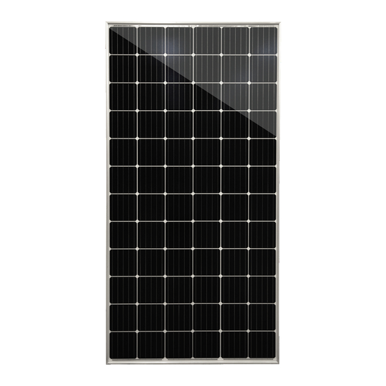
Mission Solar Energy Perc 72 Series User Manual

Mission Solar Energy Perc 72 Series User Manual

Hide thumbs Also See for Perc 72 Series:

Advertisement

Module Installation
& User Manual
|
R E V : R 2
R E V I S I O N DA T E : 1/ 2 9 / 2 0 2 1
PERC
Series
Module Types
MSExxxSX6S
MSExxxSX6W
MSExxxSX6Z
MSExxxSX5T
MSExxxSX5K
MSExxxSX5R

Advertisement

Table of Contents
loading
Need help?

Need help?

Do you have a question about the Perc 72 Series and is the answer not in the manual?

Questions and answers

Subscribe to Our Youtube Channel

Summary of Contents for Mission Solar Energy Perc 72 Series

  • Page 1 PERC Series Module Installation & User Manual Module Types R E V : R 2 R E V I S I O N DA T E : 1/ 2 9 / 2 0 2 1 MSExxxSX6S MSExxxSX6W MSExxxSX6Z MSExxxSX5T MSExxxSX5K MSExxxSX5R...
  • Page 2: Table Of Contents

    P A G E 1 O F 1 7 T A B L E O F C O N T E N T S 1 . 0 D I SC LA I ME R ................... . 2 2 .
  • Page 3: Disclaimer

    Mission Solar Energy is not responsible for the accuracy of said contents or results of your use of the same. Under no circumstances will Mission Solar Energy be liable to you or any third party for damages arising under any legal theory including contract, tort, negligence or strict liability or for direct, indirect, special, consequential;...
  • Page 4: Safety

    It is advised that modules be installed at least 500m away from the sea. FIRE Mission Solar Energy modules hold PV Type 1 fire rating in • MECHANICAL accordance with the UL 61730 standard.
  • Page 5: Operating Conditions

    P A G E 4 O F 1 7 OPERATING CONDITIONS TEMPERATURE All the modules must be mounted in environments that ensure they operate within the following minimum and maximum ambient air temperatures: • Minimum ambient air temperatures: -40 C (-40 Maximum ambient air temperatures : +40 C (104 •...
  • Page 6: 7.0 Unpacking & Storage

    P A G E 5 O F 1 7 Always wear Proper PPE when handling MSE Panels 7.0 UNPACKING & STORAGE GENERAL INSTRUCTIONS Store modules in an environment consistent with prudent solar industry practices, including, storage in dry conditions such that Do not carry the module above the head.
  • Page 7: Unpacking Instructions

    P A G E 6 O F 1 7 UNPACKING INSTRUCTIONS Always wear Proper PPE when handling MSE Panels Cut the two green strips of banding Prior to unpacking, ensure pallet is set Lift the pallet lid and set it away from material with scissors.
  • Page 8 P A G E 7 O F 1 7 Always wear Proper PPE when handling MSE Panels (Optional) If tape has been used to The first module must be separated and When four modules remain, the stack provide additional support to module pulled out with additional care so as to will inherently become prone to tipping stack, peel tape back as needed to...
  • Page 9: Product Specification

    P A G E 8 O F 1 7 PRODUCT SPECIFICATION Mission Solar PV Modules have been certified to UL61730 for a maximum design load on the back of the module of up to 1600Pa and a maximum design load on the front of the module of up to3600Pa. The performance of solar modules is defined on the standard test conditions (STC).
  • Page 10: 9.0 Mechanical Installation

    P A G E 9 O F 1 7 TAB L E 4: E L EC TR IC A L R A TIN G S O F M S E P ER C 6 0 ( 6B B , B L A CK B AC K S H E ET) M O D UL E S ER I E S Parameters MSE330SX5T MSE335SX5T...
  • Page 11: Ground Mount

    P A G E 1 0 O F 1 7 • Always follow the instructions and safety precautions from the installation guide that came with the support frame to be used. • Drilling holes on the module’s frame and glass parts is not recommended as it will void the warranty. •...
  • Page 12 P A G E 1 1 O F 1 7 TABLE 7: DESIGN LOAD AS SPECIFIED BY UL61730 I N S T A L L A T I O N * M O U N T I N G D I S T A N C E F R O N T O F M O D U L E B A C K O F M O D U L E M O D U L E...
  • Page 13 P A G E 1 2 O F 1 7 • The recommended standoff height is 150 mm. If other mounting means are employed this may affect the UL Listing or the fire class ratings. • Minimum slope of 5 in/ft for installation over a roof is required to maintain the fire class ratings. The PV modules are designed for a maximum altitude of 2000m.
  • Page 14 P A G E 1 3 O F 1 7 MSE PERC 60 SX5T/SX5K SERIES MSE PERC 66 SX5R SERIES M I S S I O N S O L A R E N E R G Y L L C ELECTRONIC versions are uncontrolled except when accessed directly from document control directory.
  • Page 15: Weeb-Uir

    NEC requirements for grounding solar electrical systems. In order to install on anodized aluminum frames, Mission Solar Energy modules shall be grounded using grounding hardware that has been certified to meet requirements for grounding systems in UL467, UL61730 or UL1741, which Mission Solar Energy recommends one of the following methods of grounding the module frame.
  • Page 16: Local / National Code And Local Regulation

    P A G E 1 5 O F 1 7 • Install the modules so that water from rain or 11.0 ELECTRICAL INSTALLATION condensation cannot penetrate inside the cable LOCAL / NATIONAL CODE AND LOCAL 11.1 conduits. REGULATION • Fix cables to the structure so that the connectors are protected from water ingress.
  • Page 17: Connectors

    VISUAL INSPECTION 12.1 Mission Solar Energy recommends that PV systems be CONNECTORS 11.3 periodically inspected by the installer or other qualified • Keep connectors dry and clean. Ensure that personnel. The purpose of the PV system inspection is to...
  • Page 18 P A G E 1 7 O F 1 7 M I S S I O N S O L A R E N E R G Y L L C ELECTRONIC versions are uncontrolled except when accessed directly from document control directory. Printed copies are uncontrolled unless verified against online document. C O P Y R I G H T 2 0 2 0 M I S S I O N S O L A R E N E R G Y L L C , A L L R I G H T S R E S E R V E D REVISION: R2 RELEASE DATE: 9/25/2020...

Table of Contents