Table of Contents
Advertisement
Advertisement
Table of Contents

Related Manuals for Mission Solar Energy MONO Series


Summary of Contents for Mission Solar Energy MONO Series
-
Page 1: Module Installation
MODULE INSTALLATION AND USER MANUAL - PERC AND MONO SERIES REV10 | 6/12/2019... -
Page 2: Table Of Contents
P A G E 1 O F 1 8 T AB LE OF CO NT EN T S 1.0 DISCLAIMER ................3 2.0 HANDLING AND USE ..............3 3.0 LIMITATION OF LIABILITY AND LIMITED REMEDIES ......3 4.0 GENERAL INSTRUCTIONS ............... 3 FIGURE 1: OVERVIEW OF MSE PERC / MONO 72-cell .................. - Page 3 P A G E 2 O F 1 8 12.0 ELECTRICAL INSTALLATION ............15 12.1 Local / National Code and Local Regulation ..................15 12.2 Wiring ..............................15 12.3 Connectors ............................16 12.4 Diodes ..............................16 13.0 MAINTENANCE ................17 13.1 Visual Inspection ...........................
-
Page 4: Disclaimer
Under no circumstances will Mission Solar Energy be liable to you or any third party for damages arising under any legal theory including contract, tort, negligence or strict liability or for direct, indirect, special, consequential; or punitive damages of any kind, including lost profits. -
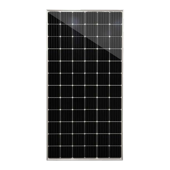
Page 5: Figure 1: Overview Of Mse Perc / Mono 72-Cell
P A G E 4 O F 1 8 FIGURE 1: OVERVIEW OF MSE PERC / MONO 72-cell FIGURE 2: OVERVIEW OF MSE PERC 60-cell M I S S I O N S O L A R E N E R G Y L L C ELECTRONIC versions are uncontrolled except when accessed directly from document control directory. -
Page 6: Safety
FIRE dwellings that have been formally analyzed for • Mission Solar Energy modules have a Type 1, Class C fire structural integrity, and confirmed to be capable of resistance rating in accordance with the IEC 61730 and UL handling the additional weighted load of PV system 1703 standard. -
Page 7: Operating Conditions
P A G E 6 O F 1 8 OPERATING CONDITIONS TEMPERATURE All the modules must be mounted in environments that ensure they operate within the following maximum and minimum operating temperatures. • Maximum Operating Temperatures: +90 C (194 • Minimum Operating Temperatures: -40 C (-40 INSTALLATION CONDITION... -
Page 8: Unpacking & Storage
P A G E 7 O F 1 8 Always wear Proper PPE when handling MSE Panels UNPACKING & STORAGE GENERAL INSTRUCTIONS Store modules in an environment consistent with prudent solar industry practices, including, storage in dry conditions such that Do not carry the module above the head. - Page 9 P A G E 8 O F 1 8 UNPACKING Always wear Proper PPE when handling MSE Panels Cut the two green strips of banding Prior to unpacking, ensure pallet is set Lift the pallet lid and set away from material with scissors.
- Page 10 P A G E 9 O F 1 8 (Optional) If tape has been used to The first module must be separated and When four modules remain, the stack provide additional support to module pulled out with additional care so as to will inherently become prone to tipping stack, peel tape back as needed to not scratch the modules.
-
Page 11: Product Specification
P A G E 1 0 O F 1 8 PRODUCT SPECIFICATION PV Modules have been certified to IEC 61215 for a maximum static load on the back of the module of up to 2400 Pa (i.e. wind load) and a maximum static load on the front of the module of up to either 2400 Pa or 5400 Pa (i.e. -
Page 12: Table 3: Electrical Ratings Of Mse Perc 60 (5Bb, Black) Module Series
P A G E 1 1 O F 1 8 TAB L E 3: E L EC TR IC A L R A TIN G S O F M S E P ER C 6 0 ( 5B B , B L A CK ) M O DU L E S ER I E S Open Circuit Maximum Rated Current at... -
Page 13: Mechanical Installation
P A G E 1 2 O F 1 8 10.0 MECHANICAL INSTALLATION The module is considered to be in compliance with IEC 61730 and UL 1703 only when the module is mounted in the manner specified by the mounting instructions below. We recommend using the following orientation to install the module. -
Page 14: Mounting Clamps
P A G E 1 3 O F 1 8 10.1 MOUNTING CLAMPS Use the mounting holes as a reference - 297 mm (MSE PERC 60) or 370 mm (for MSE PERC 72) for mounting clamp location. Make sure that the module is evenly between the two rails and sits perpendicular on the railing. If the module is not perpendicular, slightly adjust the end-clamp positions to get the proper alignment. -
Page 15: Grounding Instructions
NEC requirements for grounding solar electrical systems. In order to install, Mission Solar Energy modules shall be grounded using grounding hardware that has been certified to meet requirements for grounding systems in UL467, UL1703 or UL1741 on anodized aluminum frames. Mission Solar Energy recommends one of the following methods of grounding the module frame. -
Page 16: Electrical Installation
P A G E 1 5 O F 1 8 • If you need additional cables, you must use 12.0 ELECTRICAL INSTALLATION exclusively solar cable 12AWG/4mm2 12.1 LOCAL / NATIONAL CODE AND minimum cross-sections, with ability to work in a LOCAL REGULATION temperature range of at least -40 C and 90... -
Page 17: Connectors
12.4 DIODES • The junction boxes used with Mission Solar Energy modules contain bypass diodes wired in parallel with the PV cell strings. • In the case of partial shading, the diodes bypass the current generated by the non-shaded cells, thereby limiting modules heating and performance losses. -
Page 18: Maintenance
13.0 MAINTENANCE 13.1 VISUAL INSPECTION Mission Solar Energy recommends that PV systems be periodically inspected by the installer or other qualified personnel. The purpose of the PV system inspection is to ensure that all system components are functioning properly. At a minimum, this inspection should confirm the following: •... - Page 19 P A G E 1 8 O F 1 8 M I S S I O N S O L A R E N E R G Y L L C ELECTRONIC versions are uncontrolled except when accessed directly from document control directory. Printed copies are uncontrolled unless verified against online document. C O P Y R I G H T 2 0 1 9 M I S S I O N S O L A R E N E R G Y L L C , A L L R I G H T S R E S E R V E D R E V I S I O N : [ R 1 0 ] 6 / 1 2 / 2 0 1 9 R E L E A S E D A T E : 1 1 / 1 6 / 2 0 1 6...
Need help?
Do you have a question about the MONO Series and is the answer not in the manual?
Questions and answers