Table of Contents
Advertisement
Quick Links
PROJECT:
LOCATION:
SUBMITTED BY:
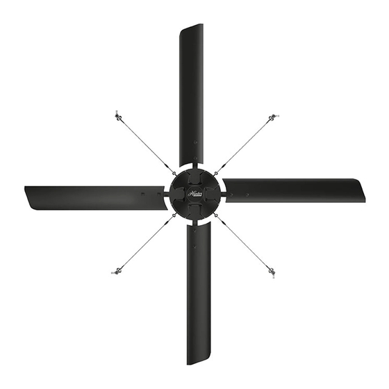
FAN MODEL
DIAMETER
DOWNROD
WALL CONTROL
VARIABLE FREQUENCY DRIVE
AC 3PH 380-480V 60Hz
AC 1PH 200-240V 60Hz
AC 3PH 200-240V 60Hz
I-BEAM MOUNTING HARDWARE
INSTALLATION
COMMENTS
NOTES
Fan(s) will be located at the nearest location(s) as per building plans.
Wall control location(s) to be identified by owner at time of installation.
IF A TOUCHSCREEN IS SELECTED: Owner must provide 110V outlet within 6' of touchscreen control location.
IF INSTALLATION IS TO BE PERFORMED BY OTHERS: Installation and site preparation to be performed by others at owner's request.
IF GOLD LEVEL INSTALLATION: Basic mechanical installation includes: scissor lift rental (if necessary), mounting all fans and equipment, routing all
communication cables, connecting fans and controls (if applicable) to power supply, and factory authorized startup and commissioning.
*CUSTOMER IS RESPONSIBLE FOR PROVIDING POWER SUPPLY TO 15' FROM EACH FAN LOCATION PRIOR TO FAN INSTALLATION*
IF PLATINUM LEVEL INSTALLATION: Full turnkey installation includes: routing all electrical wire and conduit from each fan location to electrical
panel, terminating electrical connections with NEMA rated receptacles, scissor lift rental (if necessary), mounting all fans and equipment, routing all
communication cables, connecting fans and control (if applicable) to power supply, routing low voltage fire relay cable from each fan location to security
panel (if fire relay tie-in is required – Customer's fire/security company to land final connections), and factory authorized startup and commissioning.
P: 629.333.7100 | F: 615.232.3891 | TOLL: 1.844.591.FANS (3267) 180 THREET INDUSTRIAL ROAD, SMYRNA 37167 |
ECO
20 '
18 '
16 '
14 '
24 '
8 ' 10 '
12 '
60" Downrod Assembly
120" Downrod Assembly
108" Downrod Assembly
96" Downrod Assembly
84" Downrod Assembly
72" Downrod Assembly
48" Downrod Assembly
36" Downrod Assembly
24" Downrod Assembly
Platinum Level Installation (Premium Turnkey)
Gold Level Installation (Basic Mechanical)
To Be Performed By Others
HUNTERFAN.COM/INDUSTRIAL
Advertisement
Table of Contents

Related Manuals for Hunter ECO 14


Summary of Contents for Hunter ECO 14
- Page 1 PROJECT: LOCATION: SUBMITTED BY: FAN MODEL DIAMETER 8 ' 10 ' 12 ' 14 ' 16 ' 18 ' 20 ' 24 ' DOWNROD 24" Downrod Assembly 36" Downrod Assembly 48" Downrod Assembly 60" Downrod Assembly 72" Downrod Assembly 84" Downrod Assembly 96"...
-
Page 2: Power & Efficiency
POWER & EFFICIENCY AC 1PH 200-240V 50/60Hz AC 3PH 200-240V 50/60Hz AC 3PH 380-480V 50/60Hz INPUT POWER OPTIONS CURRENT AT MAX SPEED (Amp) 4.5 - 3.9 A 2.4 - 2.1 A 2.0 - 1.6 A POWER (hp) BLDC Motor 5/8 HP 107 RPM MAXIMUM SPEED (RPM) 70 ft Dia | 4,900 sqft... -
Page 3: Safety And Precautions
Do not make any changes to any part of the fan without first consulting Hunter Industrial Fan. Installation is to be in accordance with the National Electrical Code, ANSI/NFPA 70-1999 and local codes. -
Page 4: Windy Conditions
Our fans are engineered with safety features that prevent pieces of the fan from falling in the unlikely event of a catastrophic failure. Install the retention cable on EVERY fan. The retention cable, if installed per Hunter Industrial Fan specifications, will provide comprehensive protection of people, equipment, and property in the unlikely event of mounting system failure. -
Page 5: Sprinkler Systems And Fan Placement
FAN PLACEMENT SPRINKLER SYSTEMS AND FAN PLACEMENT In any installation where fire sprinklers are in place, the fan should not interfere with their correct operation. Fans should be located no less than 3 feet below a sprinkler, and placed central to each sprinkler quadrant. Our industrial control panel can be connected to a fire relay system, which, in an emergency, will stop fans in case of fire. -
Page 6: Maintenance
MAINTENANCE GUY WIRE CHECK Checking a fan’s guy wires for tension and inspecting for frayed sections could prevent a problem before it occurs. Fan owners should confirm that the guy wires are not wrapped around any sharp edges. We recommend attaching guy wires to the building with provided clamps to prevent fraying. - Page 7 IN THE BOX FAN COMPONENTS MOUNTING HARDWARE KIT GUY WIRE KIT COMMUNICATON KIT FAN COMPONENTS MOUNTING HARDWARE KIT GUY WIRE KIT COMMUNICATON KIT a) ) (1) Downr a) a) (2) S a) a) (1) Gripple a) ) (1) 100ft Cat5 Cab b) b) (2) Cl b) b) (4) Beam Cl (Terminated)
- Page 8 CONTROL 350 SERIES TOUCHSCREEN CONTROLLER [3.05] 77.44 [0.203] 5.16 4 places [3.95] [2.00] 100.31 50.80 [2.06] 52.26 [2.73] 69.31 [3.55] 90.14 • Comes standard on XP and Eco Fans • Plug-n-Play design • Simple control of speed and direction • Standard junction box •...
- Page 9 149.31 [3.59] [4.30] 91.20 109.31 UP TO 10 FANS 4.3” TOUCHSCREEN • Compatible with all Hunter Industrial Fans • Simple intuitive user Interface NUMBER OF FANS CONTROLLED UP TO 10 FANS • Standard on Titan ACTIVE DISPLAY AREA 4.3” DIAGONALLY •...
- Page 10 CONTROL 700 SERIES TOUCHSCREEN CONTROLLER [7.69] 195.20 [5.18] [4.04] 131.60 102.70 TOUCHSCREEN • Optional Environmental Control NUMBER OF FANS CONTROLLED UP TO 30 FANS • BMS Integration with optional gateway • Control up to 30 fans with network solutions to ACTIVE DISPLAY AREA 7”...
-
Page 11: Bacnet Gateway
OPTIONS FOR CONTROLS BACNET GATEWAY BACNET GATEWAY • Simple approach to OPERATING ENVIRONMENT TEMPERATURE -20° TO 70°C/(-4° TO 158°F) interface fans to a Building OPERATING ENVIRONMENT HUMIDITY 10-95% RH NON-CONDENSING Management System • Enables remote monitoring, INPUT VOLTAGE 24VAC 125MA, 12-24VDC 250MA @ 12VDC control and visualization of a ENCLOSURE RATING IP67... - Page 12 OPTIONS FOR CONTROLS CONTROL CABLE REPEATER BACNET GATEWAY • Extend standard Cat 5e/Cat OPERATING ENVIRONMENT TEMPERATURE -40° TO 75°C (-40° TO 167°F) 6 Ethernet cable runs an OPERATING ENVIRONMENT HUMIDITY 10-95% RH NON-CONDENSING additional 100M without loss of transfer speed INPUT VOLTAGE CLASS 2 POWER SUPPLY: 12-48VDC, 18-30VAC 50/60HZ •...
- Page 13 ELECTRICAL...
- Page 14 FIRE PANEL (FIELD WIRING) DRY CONTACTS: NORMALLY CLOSED FIRE RELAY • On the Terminal Strip mounted to the outside of the VFD enclosure a Jumper will be in place on terminals “S” and “C”. Remove the Jumper from C SA terminals “S”...
- Page 15 FIRE PANEL (FIELD WIRING) FIRE RELAY ARRANGEMENT FOR MULTIPLE FANS (30 FAN MAXIMUM) Normally Energized/Unenergized Fire Panel 10-40VDC VFD Enclosure VFD Enclosure VFD Enclosure VFD Enclosure with Fire Relay without Fire Relay without Fire Relay without Fire Relay Dry Contacts Fire Panel Normally Closed...
- Page 16 ECO 14...
Need help?
Do you have a question about the ECO 14 and is the answer not in the manual?
Questions and answers