Table of Contents
Advertisement
Quick Links
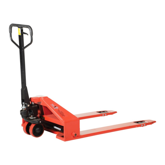
PM2-3344-SLP Super Low Profile Pallet Trucks
After delivery, immediately remove the packaging from the product in a manner that preserves the packaging and
maintains the orientation of the product in the packaging; then inspect the product closely to determine whether it
sustained damage during transport. If damage is discovered during the inspection, immediately record a complete
description of the damage on the bill of lading. If the product is undamaged, discard the packaging.
NOTES:
1) Compliance with laws, regulations, codes, and non-voluntary standards enforced in the location where the product
is used is exclusively the responsibility of the owner/end-user.
2) Vestil is not liable for any injury or property damage that occurs as a consequence of failing to apply either: a) the
instructions in this manual; or b) information provided on labels affixed to the product. Neither is Vestil responsible
for any consequential damages sustained as a result of failing to exercise sound judgment while assembling, installing,
using or maintaining this product.
Table of Contents
Product specifications...................................................................................................................... 2
Signal words.................................................................................................................................. 3
Safe use recommendations................................................................................................................ 3
FIG. 1A: PLC-P-FM exploded parts diagram and bill of materials............................................................... 4
FIG. 1B: Adjust pail stops............................................................................................................................... 4
Height adjustment............................................................................................................................ 5
FIG. 2: Height adjustment diagram...................................................................................................... 5
Use instructions.............................................................................................................................. 5
FIG. 3: Center pail beneath platen...................................................................................................... 5
FIG. 4: Adjust burper plunger assembly................................................................................................ 5
Inspections & Maintenance............................................................................................................... 6
Label placement diagram................................................................................................................. 6
Limited warranty............................................................................................................................. 7
Copyright 2015 Vestil Manufacturing Corp.
rev. 3/3/2015
Vestil Manufacturing Co.
2999 North Wayne Street, P.O. Box 507, Angola, IN 46703
Telephone: (260) 665-7586 -or- Toll Free (800) 348-0868
Fax: (260) 665-1339
www.vestilmfg.com
Instruction Manual
e-mail:
sales@vestil.com
PM2-3344-SLP, MANUAL.doc
1 of 6
Advertisement
Table of Contents

Related Manuals for Vestil PM2-3344-SLP


Summary of Contents for Vestil PM2-3344-SLP
-
Page 1: Table Of Contents
Use instructions……………………………………………………………………………………………………………… 5 FIG. 3: Center pail beneath platen………………………………………………………………………………………… 5 FIG. 4: Adjust burper plunger assembly…………………………………………………………………………………… 5 Inspections & Maintenance………………………………………………………………………………………………… 6 Label placement diagram……...………………………………………………………………………………………….. 6 Limited warranty…...……………………………………………………………………………………………………….. 7 Copyright 2015 Vestil Manufacturing Corp. 1 of 6... -
Page 2: Product Specifications
Immediately tag the unit “Out of service”. Restore the unit to normal operating condition before returning it to service. DO NOT attempt to resolve any problem(s) with the product unless you are both authorized to do so and certain that it will be safe to use afterwards. DO NOT use this device UNLESS all product labels (see “Label Placement Diagram” on p. 5) are readable and undamaged. Proper use, maintenance, and storage are essential for this product to function properly. o Keep the product clean & dry. o Vestil bears no responsibility for problems that result as a consequence of using unapproved replacement parts. Contact Vestil to order authorized replacements and spare parts for this equipment. Copyright 2015 Vestil Manufacturing Corp. 2 of 6... - Page 3 Step 3. Use a hammer to insert the axle pin through the holes Step 4. Feed the chain behind the pivot and through the axle pin hole and into the release in the receiver; then hammer spring pins through the ends of the axle pin (grooves are provided in the receiver holes for the lever cavity (also see step 1). The threaded spring pins.] Remove the shipping pin. The shipping pin is not shaft and lock nut at the end of the chain should fit in the release part of the finished assembly. lever as shown below. Spring Threaded pin shaft Axle pin Groove for spring pin Lock nut Release Shipping lever Copyright 2015 Vestil Manufacturing Corp. 3 of 6...
-
Page 4: Height Adjustment
1. Control level in the DRIVE position: a. If the forks elevate while pumping the handle up‐and‐down, the lock nut (see step 5 above; fastened to the end of the threaded shaft) requires adjustment. Turn the nut clockwise; then pump the handle again to determine if the forks still rise. Continue to turn the nut clockwise until the forks no longer rise. b. If pumping the handle causes the forks to lower, turn the lock nut counterclockwise. Turn the nut counterclockwise until the forks no longer descend. 2. Control lever in the LOWER position: a. If the forks do not lower, turn the lock nut clockwise. Turn the nut clockwise until the forks lower. 3. Control lever in the RAISE position: a. If the forks do not rise while pumping the handle, turn the nut counterclockwise. Continue to turn the nut until the forks rise properly. Copyright 2015 Vestil Manufacturing Corp. 4 of 6... -
Page 5: Inspections & Maintenance
Copyright 2015 Vestil Manufacturing Corp. 5 of 6... -
Page 6: Limited Warranty
The warranty period for original dynamic components is 90 days. For wearing parts, the warranty period is 90 days. The warranty periods begin on the date when Vestil ships the product to the warrantee. If the product was purchased from an ...
Need help?
Do you have a question about the PM2-3344-SLP and is the answer not in the manual?
Questions and answers