Table of Contents
Advertisement
Quick Links
TABLE OF CONTENTS
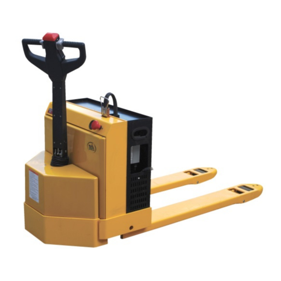
EPT-Series Electric Pallet Trucks
Receiving Instructions
After delivery, remove the packaging from the product. Inspect the product closely to determine whether it
sustained damage during transport. If damage is discovered, record a complete description of it on the bill of lading.
If the product is undamaged, discard the packaging.
NOTE: The end-user is solely responsible for confirming that product design, use, and maintenance comply with
laws, regulations, codes, and mandatory standards applied where the product is used.
Technical Service & Replacement Parts
For answers to questions not addressed in these instructions and to order replacement parts, labels, and
accessories, call our Technical Service and Parts Department at (260) 665-7586. The Department can also be
contacted online at https://www.vestil.com/page-parts-request.php.
Electronic Copies of Instruction Manuals
Additional copies of this instruction manual may be downloaded from
TABLE OF CONTENTS
Specifications
Remove the EPT from Shipping Pallet
Lifting & Transporting Loads
Batteries & Battery Charger
Replacing Forward/Reverse Contactor
Changing Drive Wheel Assembly
TABLE OF CONTENTS
9/1/2021
2999 North Wayne Street, P.O. Box 507, Angola, IN 46703
Telephone: (260) 665-7586 -or- Toll Free (800) 348-0868
Website:
Instruction Manual
EPT-45
PAGE
TABLE OF FIGURES
2
Fig. 1A EPT Main Body Components
3
Fig. 1B EPT-30 (optional) Scale Components
3
Fig. 2 EPT-30 Hydraulic Cylinder Assembly
4
Fig. 3 EPT-30 Drive Wheel Assembly
20-21
Fig. 4A EPT-30 Forks & Carriage
20
Fig. 4B EPT-30 Forks & Carriage with Optional Scale
20-21
Fig. 5A Control Yoke & Handle Components
21
Fig. 5B Control Yoke & Handle with Optional Scale
21-22
Fig. 6 Hydraulic Pump & Motor Assemblies
23-27
Fig. 7 EPT-45 Main Housings & Supporting Structure
28-31
Fig. 8 Removable Battery Box & Components
32-36
Fig. 9 EPT-45 Cylinder & Fuse Panel
37-39
Fig. 10 EPT-45 Fork & Carriage Assemblies
40-42
Fig. 11 Function Controls, Gauges, & Safety Features
43-46
47-48
Inspections & Maintenance
49-53
Labeling Diagram
54
Limited Warranty
Copyright 2021 Vestil Manufacturing
Vestil Manufacturing
Fax: (260) 665-1339
www.vestil.com
e-Mail:
EPT-30
https://www.vestil.com/page-manuals.php
EPT MANUAL
info@vestil.com
PAGE
5
6
7
8
9
10
11-12
13-14
15
16
16
17
18
19
54-55
56
57
1
of 58
Page
.
Advertisement
Table of Contents

Related Manuals for Vestil EPT Series


Summary of Contents for Vestil EPT Series
-
Page 1: Table Of Contents
For answers to questions not addressed in these instructions and to order replacement parts, labels, and accessories, call our Technical Service and Parts Department at (260) 665-7586. The Department can also be contacted online at https://www.vestil.com/page-parts-request.php. Electronic Copies of Instruction Manuals Additional copies of this instruction manual may be downloaded from https://www.vestil.com/page-manuals.php... - Page 2 TABLE OF CONTENTS 9/1/2021 EPT MANUAL SPECIFICATIONS Specifications for EPT-series electric pallet trucks are provided on Vestil’s website. To access the appropriate specifications document, navigate this webpage: https://www.vestil.com/product.php?FID=342 Scroll down to the “Product Specifications Table”. Continue scrolling the page to the table row of the model you purchased. Click the button in the PDF column that looks like a pencil inside a box.
-
Page 3: Signal Words
SAFETY INSTRUCTIONS Vestil strives to identify foreseeable hazards associated with the use of its products, but no manual can address every conceivable risk. Minimize the likelihood of injury by observing the hazards identified below and by inspecting and maintaining the product as instructed in the MAINTENANCE &... - Page 4 Approach the pallet truck from the operator side. Lift the EPT just a few inches above the pallet. Slowly back the forklift away from the pallet, and then carefully lower the forks until the EPT rests firmly on the ground. of 58 TABLE OF CONTENTS Copyright 2021 Vestil Manufacturing Page...
- Page 5 2042 EPT-30-2042 8mm Washer 2019 EPT-30-2019 Cylinder Pivot Pin, Upper 2043 EPT-30-2043 Bolt 2020 EPT-30-2020 Cylinder Pivot Pin, Lower 2044 EPT-30-2044 Wheel Stabilizer Assembly 2045 EPT-30-2045 Upper Travel Limit Switch of 58 TABLE OF CONTENTS Copyright 2021 Vestil Manufacturing Page...
- Page 6 EPT-30-SCL-4003 6mm Flat Washer 4004 EPT-30-SCL-4004 M6 x 10 Bolt 4005 EPT-30-SCL-4005 M6 x 30 Bolt 4006 EPT-30-SCL-4006 6mm Spring Washer 4007 EPT-30-SCL-4007 M6 Nut 4008 EPT-30-SCL-4008 M6 Nut 4009 EPT-30-SCL-4009 4010 EPT-30-SCL-4010 of 58 TABLE OF CONTENTS Copyright 2021 Vestil Manufacturing Page...
- Page 7 4302 EPT-30-4302 Seal Ring 4303 EPT-30-4303 Seal Ring 4304 EPT-30-4304 O-Ring 4305 EPT-30-4305 O-Ring 4401 EPT-30-4401 4402 EPT-30-4402 Hydraulic Hose 4403 EPT-30-4403 4300 EPT-30-4300 Seal Kit (EPT 30 & 45) of 58 TABLE OF CONTENTS Copyright 2021 Vestil Manufacturing Page...
- Page 8 EPT-30-3012 Grease Seal 3029 EPT-30-3029 Brake Pad 3013 EPT-30-3013 Gear Box Casting 3030 EPT-30-3030 Brake Coil 3014 EPT-30-3014 3031 EPT-30-3031 Cap Screw Idler Gear EPT-30-MTR-BLT M6-1.0 x 185mm Motor Bolt of 58 TABLE OF CONTENTS Copyright 2021 Vestil Manufacturing Page...
- Page 9 EPT-30-1011 Bracket Pin 1021 EPT-30-1021-25 Trunion (Model EPT-2547-30) Not Shown EPT-30-EXT-RL Steel Exit Roller 1021 EPT-30-1021-20 Trunion (Model EPT-2047-30) 1012 EPT-30-1012 Push Rod Pin 1022 EPT-30-1022 22mm Snap Ring 1023 EPT-30-1023 of 58 TABLE OF CONTENTS Copyright 2021 Vestil Manufacturing Page...
- Page 10 1015 EPT-30-SCL-1015 M22 x 1.5 Lock Nut 4014 EPT-30-SCL-4014 Washer 1016 EPT-30-SCL-1016 Push Rod Clevis 4015 EPT-30-SCL-4015 Weighing Forks 1017 EPT-30-SCL-1017 Clevis Pin 4016 EPT-30-SCL-4016 M12 x 38 Bolt of 58 TABLE OF CONTENTS Copyright 2021 Vestil Manufacturing Page...
- Page 11 TABLE OF CONTENTS 9/1/2021 EPT MANUAL FIG. 5A: C ONTROL OKE AND ANDLE OMPONENTS ODELS of 58 TABLE OF CONTENTS Copyright 2021 Vestil Manufacturing Page...
- Page 12 Bearing 8112 3216 EPT-30-3216 Bearing 80113 3217 EPT-30-3217 Steering Post 3218 EPT-30-3218 M10 x 30 Bolt 3219 EPT-30-3219 10mm Washer 3220 EPT-30-3220 Handle Limit Switch 3300 EPT-30-3300 Drive Wheel System of 58 TABLE OF CONTENTS Copyright 2021 Vestil Manufacturing Page...
- Page 13 TABLE OF CONTENTS 9/1/2021 EPT MANUAL FIG. 5B: C ONTROL OKE AND ANDLE OMPONENTS ODELS WITH NTEGRAL CALE of 58 TABLE OF CONTENTS Copyright 2021 Vestil Manufacturing Page...
- Page 14 EPT-30-SCL- Bearing Housing 3215 EPT-30-SCL- Bearing 8112 3216 EPT-30-SCL- Ball Bearing 80113 3217 EPT-30-SCL- Steering Post 3218 EPT-30-SCL- M10 x 30 Bolt 3219 EPT-30-SCL- 10mm Flat Washer 3300 EPT-30-SCL- Drive Wheel Assembly of 58 TABLE OF CONTENTS Copyright 2021 Vestil Manufacturing Page...
- Page 15 4110 EPT-30-4110 Breather 4111 EPT-30-4111 Hydraulic Fluid Reservoir 4112 EPT-30-4112 Intake Strainer 4113 EPT-30-4113 Pump Retaining Bolt 4114 EPT-30-4114 Hydraulic Gear Pump 4115 EPT-30-4115 Return Tube 4116 EPT-30-4116 Relief Valve of 58 TABLE OF CONTENTS Copyright 2021 Vestil Manufacturing Page...
- Page 16 Part No. Description 3002 EPT-45-3002 Battery 3003 EPT-45-3003 Battery Charger – OEM 3003 EPT-45-3003-2 Battery Charger – Soneil 3003 EPT-45-3003-3 Battery Disconnect Connector EPT-CORD Battery Charger Cord 3004 EPT-45-3004 Battery Box of 58 TABLE OF CONTENTS Copyright 2021 Vestil Manufacturing Page...
- Page 17 Main Circuit Contactor 3200 EPT-45-3200 Hydraulic Hose 3406 EPT-45-3406 Forward/Reverse Contactor 3300 EPT-45-3300 Hydraulic Cylinder 3406 EPT-45-3406-2 Forward/Reverse Contactor (Curtis) 3300 EPT-45-3300-2 Hydraulic Cylinder 3407 EPT-45-3407 Pump Motor Contactor 3408 EPT-45-3408 Horn of 58 TABLE OF CONTENTS Copyright 2021 Vestil Manufacturing Page...
- Page 18 EPT-45-2025-2 Load Roller 2011 2026 Bearing EPT-45-2011 EPT-45-2026 2012 EPT-45-2012 Washer 2027 EPT-45-2027 Washer 2013 EPT-45-2013 Clevis 2028 EPT-45-2028 Roll Pin 2014 EPT-45-2014 Clevis Lock Nut EPT-45-KSA Key Switch Assembly of 58 TABLE OF CONTENTS Copyright 2021 Vestil Manufacturing Page...
- Page 19 ~2.6mph when loaded to capacity. Simply by stop button up. Turn off power by pressing the button releasing the movement control, the EPT will down. decelerate to a complete stop. of 58 TABLE OF CONTENTS Copyright 2021 Vestil Manufacturing Page...
-
Page 20: Using The Ept
Step 4: Rotate the movement control wheel in the appropriate direction to drive forward or in reverse. See “Movement Controllers” text box and the corresponding photo in FIG. 11 on p. 19. of 58 TABLE OF CONTENTS Copyright 2021 Vestil Manufacturing Page... - Page 21 LIFTING AND TRANSPORTING LOADS DO NOT operate the EPT until you read AND understand every instruction. If you do not understand an instruction, contact Vestil for clarification. To reduce the possibility of sustaining or causing serious personal injuries, ALWAYS: 1. Make sure that all other persons clear the area while you use the EPT.
- Page 22 A proper storage location is one where the unused lifter will not: 1. Interfere with or obstruct traffic or other operations; 2. Be exposed to corrosive chemicals or water, either as a consequence of weather or of worksite conditions. of 58 TABLE OF CONTENTS Copyright 2021 Vestil Manufacturing Page...
- Page 23 EPT MANUAL TROUBLESHOOTING Before performing any corrective action described in the following table, block the drive wheel off of the ground. Contact Vestil for problems at time of installation, or for any problems not addressed below. ISSUE CAUSE REMEDY Unit does not respond to Battery voltage low (battery Charge batteries.
- Page 24 Verify 24 volts going into the assembly, and that there is a good ground. If there is still no output voltage for pin 11, replace throttle assembly. See pages 32-36. of 58 TABLE OF CONTENTS Copyright 2021 Vestil Manufacturing Page...
- Page 25 Slightly loosen up the two scews then die. that hold the switch in place, this may free the switch. If it is still stuck, contact the factory for a replacement switch. of 58 TABLE OF CONTENTS Copyright 2021 Vestil Manufacturing Page...
- Page 26 Remove the wire to the solenoid the raise button is pressed raise coil on the pump motor. Measure the resistance, it should be around 19 ohms. If it is nearly zero ohms replace the solenoid. of 58 TABLE OF CONTENTS Copyright 2021 Vestil Manufacturing Page...
- Page 27 Verify there is 24 volts going into the assembly, and that there is a good ground. If there is still no output voltage for pin 12, replace throttle assembly. of 58 TABLE OF CONTENTS Copyright 2021 Vestil Manufacturing Page...
-
Page 28: Changing The Cylinder
(red arrow). N : Make a record of the cable connections, so that you will be able to reconnect the batteries later. of 58 TABLE OF CONTENTS Copyright 2021 Vestil Manufacturing Page... - Page 29 (photo 8); then 2) Remove the pin (see Photo 9) and collect the bushings. If the pin requires encouragement to move, use a Remove Snap flat punch and hammer. Ring Bushings Upper retaining bracket of 58 TABLE OF CONTENTS Copyright 2021 Vestil Manufacturing Page...
- Page 30 Retaining pin opening in piston rod Step 7: With a small screwdriver, remove the Seal and the O-Ring from the piston, both of which are identified in Photo 13. Seal O-Ring of 58 TABLE OF CONTENTS Copyright 2021 Vestil Manufacturing Page...
- Page 31 Seal Head Cylinder Barrel Step 10: Replace the seals; then perform steps 1 through 9 in reverse order to reassemble the cylinder and to refasten it to the pallet truck. of 58 TABLE OF CONTENTS Copyright 2021 Vestil Manufacturing Page...
-
Page 32: Changing The Throttle Assembly
Step 1: Open the throttle assembly by removing the three 5mm Allen head bolts from the underside of the handle (photo 1); then lift the base of the assembly away from the handle (photo 2). Throttle assembly Handle 5mm Allen screws of 58 TABLE OF CONTENTS Copyright 2021 Vestil Manufacturing Page... - Page 33 Remove the remaining wheel from the other side; note the orientation of the two plastic bushings (identified with arrows in photo 8). If the wheels stick or grind when rotated, contact Vestil to request replacement bushings. of 58...
- Page 34 (pressed) and the inactive position (released). The switch activator should click as it moves between positions. If the switch is stuck, or if you notice any other broken or missing components, contact Vestil to discuss replacement options.
- Page 35 An Exploded View of the belly switch appears on the next page. NOTE: In order show aligning tabs, switch cover does not appear in this picture. Magnified view of Handle Tongue (arrows point to aligning tab slots) of 58 TABLE OF CONTENTS Copyright 2021 Vestil Manufacturing Page...
- Page 36 Step 12: Make sure that the wires tuck securely inside the tiller handle; then press the assembly and handle together. Do not crush wires between the two parts as they come together. Fasten the assembly to the handle with the three 5mm Allen head bolts removed in Step 1. of 58 TABLE OF CONTENTS Copyright 2021 Vestil Manufacturing Page...
-
Page 37: Changing The Motor Controller
Step 1: Remove the screws (2) shown below; then remove the yellow cover. The battery charger is located on the left side of the unit; the Campro motor controller is adjacent to the charger and is identified with an arrow in Photo 2 below. of 58 TABLE OF CONTENTS Copyright 2021 Vestil Manufacturing Page... - Page 38 Step 3: Remove the two (1 front, 1 back) 14mm bolts that fasten the motor controller mounting plate (identified with a yellow asterisk) to the frame. Step 4: Remove the Molex connector from Step 5: Disconnect the motor controller wiring with two the motor controller. 14mm wrenches. of 58 TABLE OF CONTENTS Copyright 2021 Vestil Manufacturing Page...
- Page 39 Step 8: Verify that each of the 4 spade terminal connections on the forward / reverse motor contactor is sound. Step 9: Install a new controller by reversing steps 1 through 8. of 58 TABLE OF CONTENTS Copyright 2021 Vestil Manufacturing Page...
- Page 40 Step 2: Locate the Forward/ Reverse Contactor (FRC) – pointed to in photograph 3. The diagram identifies each of the cables that attach Campro motor controller and to the FRC. Forward/Reverse Contactor of 58 TABLE OF CONTENTS Copyright 2021 Vestil Manufacturing Page...
- Page 41 Close-up side view of the terminal on top of the FRC. Step 5: Disconnect the spade terminals (locations shown in photograph below). Red & Black wire Orange wire Green & Black wire Orange wire TABLE OF CONTENTS Copyright 2021 Vestil Manufacturing Page of 58...
- Page 42 Step 8: Install the replacement FRC by performing Steps 1 through 7 in reverse order. Similarly, if you simply lubricated the original FRC, perform steps 1, 2, 3, 6 and 7 in reverse order. TABLE OF CONTENTS Copyright 2021 Vestil Manufacturing Page of 58...
-
Page 43: Changing The Battery Charger
The following procedure will explain how to replace the existing charger with a Soneil charger. Step 1: Remove the screws (2) shown below; then remove the yellow cover. The battery charger is located on the left side of the unit. Battery Charger TABLE OF CONTENTS Copyright 2021 Vestil Manufacturing Page of 58... - Page 44 Step 4: Disconnect the red cable from the positive terminal. TABLE OF CONTENTS Copyright 2021 Vestil Manufacturing Page of 58...
- Page 45 “POS” and “NEG” into the battery compartment following the same path noted in Step 4 The mounting studs may be damaged if the nuts are over-tightened. Stop tightening each nut when you first begin to feel resistance. TABLE OF CONTENTS Copyright 2021 Vestil Manufacturing Page of 58...
-
Page 46: Troubleshooting
With the charger connected to the battery, read the output voltage of the battery charger. Depending on the battery voltage, the reading should be within the range of 26V to 29V DC. TABLE OF CONTENTS Copyright 2021 Vestil Manufacturing Page of 58... - Page 47 TABLE OF CONTENTS 9/1/2021 EPT MANUAL TABLE OF CONTENTS Copyright 2021 Vestil Manufacturing Page of 58...
-
Page 48: Installing Quencharcs
• Operating the pallet truck when battery voltage is low can cause premature motor contact failure. Step 1: The quencharcs Vestil supplies (Photo 1) have baby back terminals (circled). Remove the screws (2) shown below; then remove the yellow cover. - Page 49 Quencharc shown on horn (photo 4) Add one to the pump solenoid Add one to the horn Quencharc installed on pump solenoid. Step 3: Reinstall the yellow cover and reinstall the screws. TABLE OF CONTENTS Copyright 2021 Vestil Manufacturing Page of 58...
- Page 50 • Operating the pallet truck when battery voltage is low can cause premature motor contact failure. Step 1: The quencharcs Vestil supplies (Photo 1) have baby back terminals (circled). Remove the screws (2) shown below; then remove the yellow cover.
- Page 51 TABLE OF CONTENTS 9/1/2021 EPT MANUAL Remove wiring, noting location of each cable. Locate the brake connector. Unplug the brake. TABLE OF CONTENTS Copyright 2021 Vestil Manufacturing Page of 58...
- Page 52 TABLE OF CONTENTS 9/1/2021 EPT MANUAL Remove 4 bolts holding the motor/gearbox assembly on the unit. Remove the brake. Brake will pull out straight. Use snap ring pliers, and remove as shown. TABLE OF CONTENTS Copyright 2021 Vestil Manufacturing Page of 58...
- Page 53 TABLE OF CONTENTS 9/1/2021 EPT MANUAL Gear and key can then be taken off. Remove 4 Allen head screws. Put assembly on its' side as shown. TABLE OF CONTENTS Copyright 2021 Vestil Manufacturing Page of 58...
- Page 54 Tap motor free with mallet and remove. Remove Allen screws holding wheel on. Note: Pins need to be aligned with the holes when re-installing new wheel. Repeat instruction in reverse order to assemble. TABLE OF CONTENTS Copyright 2021 Vestil Manufacturing Page of 58...
- Page 55 4. Proper function of the hand or foot actuated mechanisms; 5. Proper battery water level; 6. Unusual noise or abnormal movement during operation; 7. Legibility and undamaged condition of all product labels. TABLE OF CONTENTS Copyright 2021 Vestil Manufacturing Page of 58...
- Page 56 Step 4: Perform all adjustments and/or repairs necessary to restore the truck to SATISFACTORY CONDITION. DO NOT modify the truck. NEVER modify the unit without the express, written approval of Vestil. Modifications automatically void the LIMITED WARRANTY and could make the truck unsafe to use.
-
Page 57: Record Of Satisfactory Condition
Replace all labels that are, damaged, missing, or not easily readable (e.g. faded). Contact the TECHNICAL SERVICE REPLACEMENT PARTS DEPARTMENT online http://www.vestilmfg.com/parts_info.htm to order replacement labels. You may also call (260) 665-7586 and ask the operator to connect you to the REPLACEMENT PARTS DEPARTMENT. TABLE OF CONTENTS Copyright 2021 Vestil Manufacturing Page of 58... - Page 58 Warrantee (you) for warranty service. Who may request service? Only a warrantee may request service. You are a warrantee if you purchased the product from Vestil or from an authorized distributor AND Vestil has been fully paid.