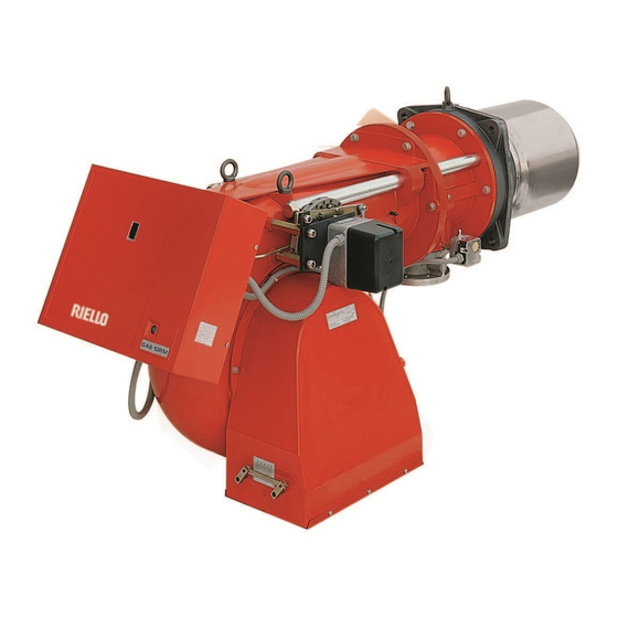
Riello GAS 5 P/M Installation, Use And Maintenance Instructions
Forced draught gas burner
Hide thumbs
Also See for GAS 5 P/M:
- Installation, use and maintenance instructions (52 pages) ,
- Installation, use and maintenance instructions (20 pages) ,
- Installation, use and maintenance instructions (64 pages)
Summary of Contents for Riello GAS 5 P/M
- Page 1 Installation, use and maintenance instructions Forced draught gas burner Progressive two-stage or modulating operation CODE MODEL TYPE 3753581 GAS 5 P/M 535 T80 2915246 (2) - 07/2016...
- Page 2 Declaration of conformity in accordance with ISO / IEC 17050-1 Manufacturer: RIELLO S.p.A. Address: Via Pilade Riello, 7 37045 Legnago (VR) Product: Forced draught gas burner Model: GAS 5 P/M These products are in compliance with the following Technical Standards:...
-
Page 3: Technical Data
TECHNICAL DATA Thermal power 155 - 660 kW - 133.300 - 567.600 kcal/h Output Operation - two stages progressive - modulating (kit with controller available upon request) Fuel natural gas Pci 8 - 10 kWh/m = 7000 - 8600 kcal/m Minimum gas pressure for maximum output 9.8 mbar are needed measured at the coupling with nil pressure in the combustion chamber and gas with calorific... -
Page 4: Maximum Dimensions
MAXIMUM DIMENSIONS Boiler front-plate Burner drilling D2192 D1785 Length available with special blast tube to be separately required. COMBUSTION CHAMBER PRESSURE - MAXIMUM OUTPUT Min. output: 155 kW - 133.300 kcal/h. D1790 Kcal/h 2915246... - Page 5 MINIMUM GAS PRESSURE - OUTPUT Pressure: detected at the pressure test-point 10) (fig. 1) with oil mbar into the combustion chamber. Should the combustion chamber be pressurized, the pressure necessary will be that of the graph plus the pressurization value. Example: to obtain 550 kW it is necessary a gas pressure of 9 mbar and the combustion head set as indicated at page 8.
-
Page 6: Gas Supply
MOUNTING TO THE BOILER Separate the blast tube from the burner body by loosening the screws 7) and 3), fix the blast tube to the boiler front plate 5) using the gasket 6) provided. Insert the burner on the holding bars 4) and fasten the screws 7) and 3). - Page 7 BURNER ELECTRICAL WIRING (carried out y the factory) 20123876 Key to layout Motor contactor LFL... Control box Burner terminal strip Fan motor Air pressure switch Thermal cut-out Servomotor Ionisation probe Plug-socket Ignition transformer Burner ground 2915246...
- Page 8 ELECTRICAL CONNECTIONS TO THE WIRING TERMINAL BLOCK (to be carried out by the installer) 16 A 25 A 1.5 mm 2.5 mm D2182 20124022 Key to layout - Load limit remote control system: shuts down the burner when the boiler temper- - Pressure probe ature or pressure reaches the preset - Temperature probe...
- Page 9 FIXING OF THE ELECTRICAL WIRES All the electrical wires, which are to be connected to the terminal block 7) (fig. 1) shall pass through the fair leads 6) (fig. 1) as per this scheme. D2184 1 - Three phase supply: fair lead Pg 21 2 - Single phase supply: fair lead Pg 13.5...
-
Page 10: Burner Start-Up Cycle
BURNER START-UP CYCLE Air-purge: loosen the screw placed on the minimal gas pressure switch mounted on the gas train . Screw Plug for pressure measure Pressure switch S7506 AIR PRESSURE SWITCH The air pressure switch setting shall be carried out after having set all other adjustments of the burner and the air pressure switch shall be at its lowest set-point. - Page 11 ADJUSTMENT BURNER Two separate adjustments have to be made: air and gas. These adjustments can be carried out when the burner is still open, during the installation (see Fixing to the boiler). Air setting Loosen the two screws 1) and move the internal part of the combustion head 2) so that its rear edge 3) is coinci- dent with the desired set-point on the plate 4).
- Page 12 ADJUSTMENT OF THE SERVOMOTOR The servomotor controls the air damper and the gas throttle valve. It is provided with three adjustable cams controlling the related change-over switches. Red cam Blue cam Orange cam Pointer Servomotor releasing lever Red cam: it controls the max. stroke, generally it is positioned on 130°.
-
Page 13: Combustion Adjustment
COMBUSTION ADJUSTMENT For the combustion adjustment we suggest to proceed in this way: - Let the burner starts and after the flame ignites at the minimum output, disconnect the servomotor by opening the con- nection 5) (page 1) placed on panel. - Thereafter proceed successively to the adjustment of the maximum, minimal outputs and to the intermediate output. - Page 14 RATIO BETWEEN THE MINIMUM AND MAXIMUM OUTPUT For a better explanation we suppose to have a burner with an adjustable output between the range 25 - 100. The ratio between the minimum and maximum output is generally included between 1 : 4 (25 - 100) and 1 : 3 (25 - 75); our burners leave the factory set for these ratio.
-
Page 15: Combustion Checks
COMBUSTION CHECKS It is advisable to not exceed 10% of CO (gas with calorific value of 8600 kcal/m3), in order to avoid the risk that small changes of the adjustments due, for instance, at draught variation, may cause combustion with insufficient air and consequently formation of CO. - Page 16 BURNER STARTING DIFFICULTIES AND THEIR CAUSES The symbol, visible on the reading disc of the pointer, shows the kind of problem. The control box does not start at the thermostats closing, because of: - lack of gas; - the gas pressure switch does not close the contact: bad set; - the air pressure switch changed over in operation position;...
- Page 20 RIELLO S.p.A. I-37045 Legnago (VR) Tel.: +39.0442.630111 http:// www.riello.it http:// www.riello.com Subject to modifications...


Need help?
Do you have a question about the GAS 5 P/M and is the answer not in the manual?
Questions and answers