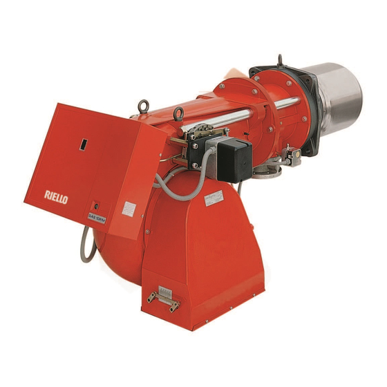
Riello GAS 3 Installation, Use And Maintenance Instructions
Forced draught gas burners
Hide thumbs
Also See for GAS 3:
- Installation, use and maintenance instructions (44 pages) ,
- Installation, use and maintenance instructions (13 pages) ,
- Installation, use and maintenance instructions (17 pages)

Related Manuals for Riello GAS 3


Summary of Contents for Riello GAS 3
- Page 1 Installation, use and maintenance instructions Forced draught gas burners Code Model Type 3751960 GAS 3 519T55 3751961 GAS 3 519T55 2915858 (3) - 03/2014...
- Page 3 The quality is guaranteed by a quality and management system certified in accordance with UNI EN ISO 9001. Legnago, Executive Director Research & Development Director 10.10.2013 RIELLO S.p.A. - Burner Department RIELLO S.p.A. - Burner Department Mr. G. Conticini Mr. R. Cattaneo 5858...
-
Page 4: Technical Data
TECHNICAL DATA Thermal output 150 ÷ 350 kW - 130,000 ÷ 300,000 kcal/h Fuel Natural gas Pci 8 - 10 kWh/m = 7000 - 8600 kcal/m For maximum output 11.1 mbar are needed measured at the coupling Minimum gas pressure with nil pressure in the combustion chamber and gas with calorific val- ue of 8600 kcal/m Maximum gas pressure... - Page 5 COMBUSTION CHAMBER PRESSURE - OUTPUT MINIMUM GAS PRESSURE - OUTPUT Pressure: Detected at the pressure test-point 8) (fig. 1) with nil mbar into the combustion chamber. Should the combustion chamber be pressurized, the pressure necessary will be that of the graph plus the pressurization value.
-
Page 6: Gas Supply
FIXING TO THE BOILER Separate the combustion head from the burner body by loosening the screws 1) and 2) and withdrawing the group A) from the holding bars 3). Fix the group B) to the boiler front plate 4) using the gasket 5) pro- vided as accessory. - Page 7 BURNER ELECTRICAL WIRING (carried out by the factory) 2565 WIRING TERMINAL STRIP (SEE PAG. 6) KEY TO LAYOUT Air pressure switch Over pressure switch Capacitor RFI Suppressor Relay Burner terminal strip Fan motor RMG Control box Ionisation probe Ignition transformer Burner earth TTENTION In the case of phase-phase feed, a bridge must be fitted on the control box terminal board between terminal 6...
- Page 8 ELECTRICAL CONNECTIONS TO THE WIRING TERMINAL STRIP (to be carried out by the installer) 2566 Warning Connect gas valves to terminals 10-11-12 only, exactly as shown on the diagram. KEY TO LAYOUT Terminal strip CPI Valve position switch Remote lock out signal Burner earth Limit load control system Safety load control system...
- Page 9 FIXING OF THE ELECTRICAL WIRES All the electrical wires, which are to be connected to the terminal block 5) (fig. 1) shall pass through the fair leads 4) (fig. 1) as for this scheme. 1 - Single phase supply: fair lead Pg 13.5 2 - Adjustment thermostat: fair lead Pg 13.5 3 - Safety thermostat:...
- Page 10 START-UP For Gas train settings, please refer to Appliance Technical Instructions. AIR PRESSURE SWITCH “1” The air pressure switch is set after adjustment have been made. Begin with the switch at the lowest setting. With the burner working at the minimum output, adjust the dial clockwise, increasing its value until the burner locks out.
-
Page 11: Combustion Head Adjustment
COMBUSTION HEAD ADJUSTMENT Two separate adjustments have to be made: air and gas. These adjustments can be carried out when the burner is still open, during the installation (see page 4 - Fixing to the boiler). Air setting Loosen the two screws 1) and move the internal part of the combustion head 2) so that its rear edge 3) is coincident with the desired set-point on the plate 4). -
Page 12: Combustion Checks
COMBUSTION CHECKS It is advisable to not exceed 10% of CO (gas with calorific value of 8600 kcal/m ), in order to avoid the risk that small changes of the adjustments due, for instance, at draught variation, may cause combustion with insufficient air and con- sequently formation of CO. -
Page 13: Operating Faults
BURNER STARTING DIFFICULTIES AND THEIR CAUSES The burner goes through the purge period normally, the flame ignites, but the burner goes to lock-out, within two seconds after the ignition if: - the ionization probe is earthed or not in contact with the flame, or its wiring to the control box is broken, or there is a fault on its insulation to earth;... - Page 14 BURNER STARTING DIFFICULTIES AND THEIR CAUSES Signal Problem Possible cause Recommended remedy 2 blinks Once the pre-purg- 1 - The operation solenoid lets little gas . Increase ing phase and safety through time have passed, 2 - One of the two solenoid valves does Replace the burner goes into not open.
- Page 15 Signal Problem Possible cause Recommended remedy 10 blinks The burner does not 32 - Incorrect electrical wiring..Check switch on, and the lockout appears The burner goes into 33 - Defective control box... . . Replace lockout 34 - Presence of electromagnetic .
-
Page 16: Normal Operation / Flame Detection Time
NORMAL OPERATION / FLAME DETECTION TIME The control box has a further function to guarantee the correct burner operation (signal: GREEN LED perma- nently on). To use this function, wait at least ten seconds from the burner ignition and then press the control box button for a minimum of 3 seconds. -
Page 17: Operating Fault Diagnostics
OPERATING FAULT DIAGNOSTICS The control box has a self-diagnostic system, which easily allows identifying the operating faults (RED LED signal). ITo use this function, wait at least ten seconds from the safety lock out, and then press the reset button for a minimum of 3 seconds. - Page 18 ACCESSORIES • RADIO DISTURBANCE PROTECTION KIT code 3010386 If the burner is installed in places particularly subject to radio disturbance (emission of signals exceeding 10 V/m) owing to the presence of an INVERTER, or in applications where the length of the thermostat connections exceeds 20 metres, a protection kit is available as an interface between the control box and the burner.
- Page 20 RIELLO S.p.A. I-37045 Legnago (VR) Tel.: +39.0442.630111 http:// www.riello.it http:// www.riello.com Subject to modifications...
Need help?
Do you have a question about the GAS 3 and is the answer not in the manual?
Questions and answers