
Related Manuals for Riello RC2-38


Summary of Contents for Riello RC2-38
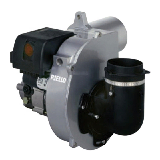
- Page 1 Installation, use and maintenance instructions Light oil burners One stage operation CODE MODEL TYPE 3571000 RC2-38 732T3 3572080 RC2.1-46 732T6 20062926 RC2.1-46 TL 732T6 2903445 (2) - 05/2017...
-
Page 3: Table Of Contents
INDEX BURNER DESCRIPTION....Combustion adjustment....10 Burner equipment ....Nozzles recommended . -
Page 4: Technical Data
TECHNICAL DATA 2.1 TECHNICAL DATA TYPE 732T3 732T6 − − Output 3.2 kg/h 3.9 kg/h − − Thermal power 38 kW 33,2 46,2 kW − Fuel Light oil, viscosity 4 6 mm /s at 20°C (H i = 11.86 kWh/kg) ±... -
Page 5: Accessories
VERSION WITH BAFFLE PLATE CF - BF 732T3 732T6 kg/h D8793 ACCESSORIES Fig. 2 BF AIR INTAKE In case of BF application, air is fed in through a flexible or rigid pipe connected to the air intake (A, fig. 5, page 4). This component is supplied separately. -
Page 6: Installation
To adjust delivery, proceed as follows: Fig. 5 loosen screw (7) and adjust the ring (8), ➤ turning it to the desired setting; secure in place by tightening screw (7) ➤ with a driving torque of 0.8 Nm. D7011 BAFFLE PLATE (see fig. 6) Fig. -
Page 7: Boiler Fixing
3.2 BOILER FIXING Secure the flange to the burner as follows: fit the screw and the two nuts (see fig. 7) on the flange (1). ➤ Widen, if necessary, the insulating gasket holes (2,fig. 8), taking care not to damage them. ➤... - Page 8 The intake-tube / burner system must not allow a loss of over 2 m /h at 0.5mbar: ➤ for instance, the above requirements will be met if you use flues for pressure exhaust of flue gases (the con- densation kind). Make sure the air intake tube’s inlet is positioned so that it is not likely to be obstructed by foreign matter and, ➤...
-
Page 9: Hydraulic Systems
3.4 HYDRAULIC SYSTEMS Fig. 10 It is necessary to install a filter on the fuel supply line. PUMP (see fig. 10) ◆ The pump is designed to allow working with two pipes . Before starting the burner make sure that the return pipe-line is ◆... - Page 10 DEPRESSURISED SYSTEMS (fig. 13 and 14) Depressurised systems have a negative fuel pressure (depression) on intake to the burner. Usually the tank is lower than the burner. ONE PIPE SYSTEM Fig. 13 TWO PIPE SYSTEM Fig. 14 D7008 ONLY FOR ITALY: L meters Automatic shut-off device as per Ministry of Internal Affairs’...
-
Page 11: Electrical Wiring
3.5 ELECTRICAL WIRING WARNING 230V 50Hz DO NOT EXCHANGE NEUTRAL WITH PHASE NOTES: – Wires of min. 1 mm section. (Unless requested oth- erwise by local standards and legislation). Main switch – The electrical wiring carried out by the installer must be in compliance with the rules in force in the Country. -
Page 12: Working
WORKING 4.1 COMBUSTION ADJUSTMENT In conformity with EN 267 the application of the burner on the boiler, adjustment and testing must be car- ried out observing the instruction manual of the boiler, including verification of the CO and CO concentra- tion in the flue gases, their temperatures and the average temperature of the water in the boiler. -
Page 13: Maintenance Position
4.4 MAINTENANCE POSITION Fig. 17 Remove the flange-fixing nut and pull out the ➤ burner. Place the burner on a horizontal surface as illus- ➤ trated in figure 17. Loosen the two screws (1) and remove the blast ➤ tube (2). Remove the diffuser disc assembly (3) from the noz- ➤... -
Page 14: Air Adjustment
4.6 AIR ADJUSTMENT, (fig. 19) Fig. 19 Depending on burner output, air must be adjusted by turning the feeder (2) first, followed by the knob (3). FEEDER ADJUSTMENT To adjust, proceed as follows: Loosen the three screws (1). ➤ Turn the feeder (2), positioning it according to the values ➤... -
Page 15: Maintenance
MAINTENANCE The burner requires periodic maintenance carried out by a qualified and authorised technician in conformity with legislation and local standards. Periodic maintenance is essential for the reliability of the burner, avoiding the excessive consumption of fuel and consequent pollution. Before carrying out any cleaning or control always first switch off the electrical supply to the burner acting on the main switch of the system. -
Page 16: Faults / Solutions
6. FAULTS / SOLUTIONS Here below you can find some causes and the possible solutions for some problems that could cause a fail- ure to start or a bad working of the burner. A fault usually makes the lock-out lamp light which is situated inside the reset button of the control box (7, fig. -
Page 17: Safety Warnings
WARNINGS AND SAFETY The dimension of the boiler’s combustion chamber must respond to specific values, in order to guarantee a combustion with the lowest polluting emissions rate. You are therefore advised to consult the Technical Assistance Department before choosing this type of burner for the combination with a boiler. - Page 20 RIELLO S.p.A. I-37045 Legnago (VR) Tel.: +39.0442.630111 http:// www.riello.it http:// www.riello.com Subject to modifications...
Need help?
Do you have a question about the RC2-38 and is the answer not in the manual?
Questions and answers