Table of Contents
Advertisement
If this burner is being installed in a packaged unit (ie. Burner comes with a boiler or furnace), follow
the installation and set-up instructions supplied with the heating unit, as settings may differ from
those in this manual.
C6501016
.DOC
OIL BURNER
R35 SERIES
INSTALLATION MANUAL
29-Mar-11
STANDARD R35 MANUAL REV 1-3
Advertisement
Table of Contents

Related Manuals for Riello R35 Series


Summary of Contents for Riello R35 Series
- Page 1 OIL BURNER R35 SERIES INSTALLATION MANUAL If this burner is being installed in a packaged unit (ie. Burner comes with a boiler or furnace), follow the installation and set-up instructions supplied with the heating unit, as settings may differ from those in this manual.
-
Page 2: Table Of Contents
SPARE PARTS LIST……………………………………………………………... 17 INSTALLATION PRECAUTION: ……………………………………………. CARTON CONTENTS Your RIELLO 35 burner carton includes the following parts. Please check to make sure all parts are present before beginning the installation. 1 – Burner 1 – Mounting Flange 1 – Mounting Gasket... -
Page 3: Burner Model Identification
SERVICE TOOLS REQUIRED 1 – No 1 Philips Screwdriver 1 - No. 2 Philips Screwdriver 1 – No. 2 Slotted Screwdriver 1 – 1 inch Adjustable Wrench 4 – Allen Keys: 2.5 mm – Pump By-pass Plug 1/8 inch – Pump Pressure Regulator 5/32 inch –... - Page 4 TECHNICAL DATA Ø B FIG. 1 FIG. 2 60º 45º DIMENSIONS – FIG.1 30º Inches 3 1/2 8 5/16 8 5/16 11 7/8 9 3/8 Tab. A DIMENSIONS – FIG.2 Inches 3 5/8 5 1/2 7 1/2 8 7/16 7 1/16 7/16 11.2 TABLE A...
-
Page 5: Specifications
SPECIFICATIONS R35.3 R35.5 FUEL No. 2 Fuel Oil 0.60 – 1.10 0.75 – 1.60 FIRING RATE Kg/h 1.89 – 3.5 2.4 – 5.0 Btu/h 81,200 – 154,000 105,200 – 224,000 EFECTIVE OUTPUT 23.8 - 45 30.8 – 65.5 VOLTAGE Single Phase 120V 60Hz (+10% - 15%) POWER CONSUMPTION 130 W 140 W... -
Page 6: Mounting The Burner
MOUNTING THE BURNER There are three possible methods to mount the burner, depending on the individual application. These are: 1.) Fixed UNIVERSAL FLANGE bolted to the boiler/furnace unit. 2.) ADJUSTABLE FLANGE bolted to the boiler / furnace unit. 3.) ADJUSTABLE FLANGE or fixed UNIVERSAL FLANGE mounted directly to optional Pedestal kit (C7001022) must be ordered separately. - Page 7 SERIAL NUMBER IDENTIFICATION The Riello 15 character serial number, example, 97 A 8511111 00025, is identified as follows: 97 = last two digits of the year of manufacture; A = BI-week of manufacture; 8511111 = burner product code; 00025 = increment of 1 for each burner produced –...
-
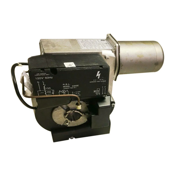
Page 8: Electrical Connections
ELECTRICAL CONNECTIONS To gain access to the line voltage terminals on the primary safety control follow items A and B below. A.) Remove drawer assembly from the burner. B.) Remove the electrical enclosure by removing the three screws. FIG. 3 (7). C.) Make electrical connections to burner as shown in FIG. -
Page 9: Field Wiring
FIELD WIRING Burner operation is controlled by using a low voltage control (24 Vac) with the standard 536SE CONTROL BOX. On some OEM applications, burner operation may be controlled by using a line voltage (120 Vac) control with the 535SE CONTROL BOX. The 536SE CONTROL BOX can also be used in a line voltage circuit, by using a WIRE JUMPER between the 24 V thermostat terminals on the 536SE CONTROL BOX. -
Page 10: Remote Sensing Of Safety Lockout Switch
535SE CONTROL BOX 120V ~ 60Hz WARNING Do not exchange neutral with phase. Switch with fuse 15A max. FIELD WIRING Limit thermostat Remote lockout lamp Regulating thermostat CONTROL BOX 535SE CARRIED-OUT IN THE FACTORY Photocell Ground Oil valve Motor Black White FIG. -
Page 11: Removal Of Drawer Assembly
REMOVAL OF DRAWER ASSEMBLY Refer to FIG. 10 A.) Disconnect the nozzle line (1) from pump. B.) Take out the retainer screws (3) of the cover. C.) Loosen the retainer screws (3) of the cover. D.) Turn the drawer assembly cover counter clockwise, and then pull out the drawer assembly while keeping the electrodes on the lift side. -
Page 12: Single Line System
OIL LINE CONNECTIONS NOTE: The oil line connections to the pump should be made only after all electrical connections are complete and the electrical enclosure has been replaced. The burner is shipped from the factory with the pump set for a single line system. To operate on a two-line system, the BY-PASS PLUG must be installed. -
Page 13: Two Line System
TWO LINE (LIFT) SYSTEM A) Install BY-PASS PLUG. (See FIG. 12) B) Suction and return lines should be the same diameter and both should extend to the same depth inside the fuel tank. Do not exceed the pipe lengths indicated below in FIG 14. C) The suction and return line connections to the pump can be made using ¼”... -
Page 14: Pump Purge
NOTE: Pump pressure is factory set at 145 psi unless otherwise specified by the equipment manufacturer. The pressure should be verified at time of burner installation. Pressure and vacuum ports are not NPT threads. Riello pressure, vacuum gauges and adapters (C7001070) for North American style gauges are available for purchase from Riello. -
Page 15: Working Field
WORKING FIELD RIELLO 35 COMBUSTION CHAMBER PRESSURE RANGE mbar in. WC 0.40 0.32 0.24 R35.3 0.16 R35.5 0.08 0.60 0.75 1.10 1.60 1.89 kg/h FIRING RATE BURNER SET-UP AND ADJUSTMENT COMBUSTION HEAD (TURBULATOR) SETTING – (FIG. 16) The TURBULATOR setting varies according to the burner output required. -
Page 16: Recommended Nozzles
BURNER SET-UP CHART To obtain the specific input requirement for the appliance, install the proper nozzle and adjust the pump pressure, then set the combustion head and air damper as indicated in the charts below. A) Determine the actual firing rate of the burner required matching the appliance input. B) From the charts below, install the proper NOZZLE to obtain the actual firing rate. -
Page 17: Amulet Installation Instructions
The amulet has been sized to fit Riello Model 40 sizes F3 and F5 plus the Riello Model R35. When installing this amulet, handle it carefully. Do not exert undue pressure when pushing the amulet over the combustion tube. -
Page 18: Spare Parts Exploded View
SPARE PARTS EXPLODED VIEW... -
Page 20: Installation Precaution
INSTALLATION PRECAUTIONS AIR FOR COMBUSTION Do not install burner in room with insufficient air for combustion. Be sure there is an adequate air supply for combustion if the boiler/furnace room is enclosed. It may be necessary to create a window to permit sufficient air to enter the boiler/furnace room. - Page 21 MAINTENANCE The periodic maintenance is essential for the good operation, safety, yield and duration of the burner. It allows you to reduce consumption and polluting emissions and to keep the product in a reliable state over time. The maintenance interventions and the calibration of the burner must only be carried out by qualified, authorized personnel, in accordance with the contents of this manual and in compliance with the standards and regulations of current laws.
- Page 24 RIELLO S.p.A. I-37045 Legnago (VR) Tel.: +39.0442.630111 http:// www.riello.it http:// www.rielloburners.com RIELLO BURNERS NORTH AMERICA 1-800-4-RIELLO 35 Pond Park Road 2165 Meadowpine Blvd Hingham, Massachusetts, 1-800-474-3556 Mississauga, Ontario U.S.A. 02043 Canada L5N 6H6 http://www.riello-burners.com Subject to modifications...
Need help?
Do you have a question about the R35 Series and is the answer not in the manual?
Questions and answers