Genie ZX-135/70 Operator's Manual
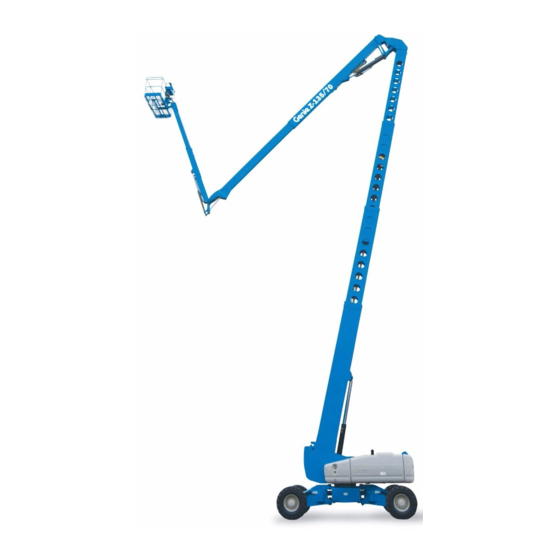
With jib - extend
Hide thumbs
Also See for ZX-135/70:
- Service manual (271 pages) ,
- Service and repair manual (253 pages) ,
- Operator's manual (65 pages)

Subscribe to Our Youtube Channel
Related Manuals for Genie ZX-135/70


Summary of Contents for Genie ZX-135/70
- Page 1 Operator's Manual -135/70 ® from ZX135H-4001 ANSI/CSA North America with Jib - Extend South America ® Asia with Maintenance Information Original Instructions Second Edition Third Printing Part No. 1272822GT...
-
Page 2: Table Of Contents
Maintenance ............74 Specifications ............78 Copyright © 2012 by Terex Corporation Second Edition: Third Printing, September 2020 Genie and "ZX" are registered trademarks of Terex South Dakota, Inc. in the U.S.A. and many other countries. These machines comply with ANSI/SAIA 92.20 CAN/CSA B354.6... -
Page 3: Introduction
This book is an operation and daily maintenance aerial work site. Before operating the machine, it’s manual for the user or operator of a Genie the operator’s responsibility to read and machine. understand this familiarization guide. - Page 4 Operator's Manual Second Edition • Third Printing Introduction Primary boom extend/retract Platform controls symbology and related machine movement: Platform level Jib boom extend/retract Platform rotate Jib boom up/down Axle extend Primary boom up/down Axle retract Turntable rotate Drive forward/reverse Secondary boom raise/extend Steer right/left Secondary boom retract/lower Square end steer...
- Page 5 Second Edition • Third Printing Operator's Manual Introduction Limitations of use: Ground controls symbology and related machine movement: The intended use of this machine is to lift personnel, including tools, and materials to an Platform level, jib boom aerial work site. up/down, primary boom extend/retract, primary boom ...
- Page 6 Bulletin Distribution and Contacting the Manufacturer Compliance At times it may be necessary to contact Genie. When you do, be ready to supply the model Safety of product users is of paramount number and serial number of your machine, along importance to Genie.
- Page 7 Second Edition • Third Printing Operator's Manual Introduction Safety Sign Maintenance Replace any missing or damaged safety signs. Keep operator safety in mind at all times. Use mild soap and water to clean safety signs. Do not use solvent-based cleaners because they may damage the safety sign material.
-
Page 8: Symbol And Hazard Pictorials Definitions
Operator's Manual Second Edition • Third Printing Symbol and Hazard Pictorials Definitions Symbol and Hazard Pictorials Definitions Keep away from Crush hazard Crush hazard Overhead obstruction Collision hazard moving parts Electrocution hazard Maintain required Tip-over hazard Tip-over hazard Tip-over hazard clearance Electrocution hazard Avoid contact... - Page 9 Second Edition • Third Printing Operator's Manual Symbol and Hazard Pictorials Definitions Fire hazard No smoking Explosion hazard No step Lanyard anchorage points Platform tie-down Lifting & tie down instructions Tie-down point Lifting point instructions Wind speed Maximum capacity Manual force Wheel load Weight of welder reduces capacity...
- Page 10 Operator's Manual Second Edition • Third Printing Symbol and Hazard Pictorials Definitions Do not use ether or Voltage rating for Pressure rating for air Tire specifications Runaway hazard other high energy power to platform line to platform starting aids on machines equipped with glow plugs.
-
Page 11: General Safety
Second Edition • Third Printing Operator's Manual General Safety General Safety ® Part No. 1272822GT -135/70... - Page 12 Operator's Manual Second Edition • Third Printing General Safety ® -135/70 Part No. 1272822GT...
- Page 13 Second Edition • Third Printing Operator's Manual General Safety ® Part No. 1272822GT -135/70...
- Page 14 Operator's Manual Second Edition • Third Printing General Safety ® -135/70 Part No. 1272822GT...
- Page 15 Second Edition • Third Printing Operator's Manual General Safety ® Part No. 1272822GT -135/70...
- Page 16 Operator's Manual Second Edition • Third Printing General Safety ® -135/70 Part No. 1272822GT...
-
Page 17: Personal Safety
Second Edition • Third Printing Operator's Manual Personal Safety Personal Safety Personal Fall Protection Personal fall protection equipment (PFPE) is required when operating this machine. Occupants must wear a safety belt or harness in accordance with governmental regulations. Attach the lanyard to the anchor provided in the platform. Operators must comply with employer, job site and governmental rules regarding the use of personal protective equipment. -
Page 18: Work Area Safety
Operator's Manual Second Edition • Third Printing Work Area Safety Work Area Safety Electrocution Hazards Keep away from the machine if it contacts This machine is not electrically insulated and will energized power lines. not provide protection from contact with or Personnel on the ground proximity to electrical current. - Page 19 Second Edition • Third Printing Operator's Manual Work Area Safety Do not raise or extend the If the tilt alarm sounds boom unless the machine with the platform uphill: is on a firm, level surface. Lower the primary boom. Retract/lower the secondary boom.
- Page 20 Operator's Manual Second Edition • Third Printing Work Area Safety Do not alter or disable machine components that in Use extreme care and any way affect safety and stability. slow speeds while driving the machine in the stowed Do not replace items critical to machine stability position across uneven with items of different weight or specification.
- Page 21 Second Edition • Third Printing Operator's Manual Work Area Safety Operation on Slopes Hazards Do not place or attach fixed or overhanging loads Do not drive the machine on a slope that exceeds to any part of this the maximum uphill, downhill or side slope rating of machine.
- Page 22 Hazards related with the specific product application of exiting at height have been considered in the design of the machine, for further information contact Genie (see section Contacting the Manufacturer). ® -135/70 Part No. 1272822GT...
- Page 23 Second Edition • Third Printing Operator's Manual Work Area Safety Bodily Injury Hazard Observe and use the color-coded direction arrows on the platform controls and drive chassis for drive Always operate the machine in a well-ventilated and steer functions. area to avoid carbon monoxide poisoning. Do not lower the boom Do not operate the machine with a hydraulic oil or unless the area below is...
- Page 24 Be sure all maintenance has been performed as specified in this manual and the appropriate Genie The contact alarm assembly weighs 10 lbs/4.5 kg. service manual. Be sure the contact alarm is securely installed.
- Page 25 Second Edition • Third Printing Operator's Manual Work Area Safety Battery Safety Pipe Cradle Safety Read, understand, and obey all warnings and Burn Hazards instructions provided with the pipe cradles. Batteries contain acid. Do not exceed the rated platform capacity. The Always wear protective pipe cradle assembly and the weight in the pipe clothing and eye wear when...
- Page 26 Operator's Manual Second Edition • Third Printing Work Area Safety Panel Cradle Safety Welder Safety Read, understand and obey all warnings and Read, understand and obey all warnings and instructions provided with the panel cradles. instructions provided with the welding power unit. Do not exceed the rated platform capacity.
- Page 27 Second Edition • Third Printing Operator's Manual Work Area Safety Lockout After Each Use Select a safe parking location—firm level surface, clear of obstruction and traffic. Retract and lower the boom to the stowed position. Rotate the turntable so that the boom is between the non-steer wheels.
-
Page 28: Legend
Operator's Manual Second Edition • Third Printing Legend Legend Square-end tire Circle-end tire Ground controls Platform controls Secondary boom Sliding mid-rail Primary boom 10 Manual storage container Jib boom 11 Lanyard anchorage points Platform 12 Foot switch ® -135/70 Part No. 1272822GT... -
Page 29: Controls
Second Edition • Third Printing Operator's Manual Controls Controls The ground control station is to be used as a means to raise the platform for storage purposes and for function tests. The ground control station can be used in the event of an emergency to rescue an incapacitated person in the platform. - Page 30 Operator's Manual Second Edition • Third Printing Controls Turntable rotate right button LCD readout screen Press the turntable rotate right button and the turntable will rotate right. Turntable rotate left button a low fuel indicator Press the turntable rotate left button and the turntable will rotate left.
- Page 31 Second Edition • Third Printing Operator's Manual Controls 11 Engine start button 18 Platform rotate right button Press the engine start button to start the Press the platform rotate right button and the engine. platform will rotate right. 12 Jib boom up/down buttons 19 Platform rotate left button Press the jib boom up button and the jib boom Press the platform rotate left button and the...
- Page 32 Operator's Manual Second Edition • Third Printing Controls Platform Control Panel ® -135/70 Part No. 1272822GT...
- Page 33 Second Edition • Third Printing Operator's Manual Controls 15 16 STOP ® Part No. 1272822GT -135/70...
- Page 34 Operator's Manual Second Edition • Third Printing Controls Platform Control Panel Auxiliary power switch with indicator light Use auxiliary power if the primary power Horn button source (engine) fails. Press this button and the horn will sound. Simultaneously hold the auxiliary power switch Release the button and the horn will stop.
- Page 35 Second Edition • Third Printing Operator's Manual Controls 11 Engine idle select switch with indicator light: 18 Dual axis proportional control handle for drive and steer functions. Move this switch to select engine idle setting. Rabbit Proportional control handle for drive function symbol light on indicates high and thumb rocker for steer function.
- Page 36 Operator's Manual Second Edition • Third Printing Controls 23 Dual axis proportional control handle for jib 19 Steer mode select switch with indicator lights boom up/down and platform rotate left/right functions Move the steer mode select switch Move the control handle to choose steer up and the jib boom will mode.
- Page 37 Second Edition • Third Printing Operator's Manual Controls 26 Thumb rocker switch for primary boom extend/retract function Push the top of the rocker switch and primary boom will retract. Push the bottom of the rocker switch and the primary boom will extend.
-
Page 38: Inspections
Operator's Manual Second Edition • Third Printing Inspections Inspections Pre-operation Inspection Fundamentals It is the responsibility of the operator to perform a pre-operation inspection and routine maintenance. The pre-operation inspection is a visual inspection performed by the operator prior to each work shift. Do Not Operate Unless: The inspection is designed to discover if anything is apparently wrong with a machine before the... - Page 39 Second Edition • Third Printing Operator's Manual Inspections Pre-operation Inspection Steer and axle sensors Alarms and beacons (if equipped) Be sure that the operator’s, safety, and Nuts, bolts and other fasteners responsibilities manuals are complete, legible and in the storage container located in the ...
- Page 40 Operator's Manual Second Edition • Third Printing Inspections Function Test Fundamentals The function tests are designed to discover any malfunctions before the machine is put into service. The operator must follow the step-by-step instructions to test all machine functions. A malfunctioning machine must never be used. If malfunctions are discovered, the machine must be Do Not Operate Unless: tagged and removed from service.
- Page 41 Second Edition • Third Printing Operator's Manual Inspections At the Ground Controls Test the Extendable Axles Note: Start this test with the axles retracted. Select a test area that is firm, level and free of hazards. At the ground controls, push and hold a function enable/speed select button and push Turn the key switch to ground control.
- Page 42 Operator's Manual Second Edition • Third Printing Inspections 10 Push and hold a function enable/speed select 14 Push and hold a function enable/speed select button and push the turntable rotate left button. button and push the primary boom up button and then the primary boom down button.
- Page 43 Second Edition • Third Printing Operator's Manual Inspections Test Machine Functions Test the Tilt Sensor 18 Do not press and hold a function enable/speed 24 Press one of the LCD select button. Attempt to activate each boom screen control buttons until and platform function button.
- Page 44 Operator's Manual Second Edition • Third Printing Inspections 32 Press and hold the secondary boom up/extend Test the Operating Envelope button. Result: The secondary boom should raise and 27 Press the LCD screen the LCD screen should display the secondary control buttons shown until boom angle in degrees.
- Page 45 Second Edition • Third Printing Operator's Manual Inspections Test the Foot Switch At the Platform Controls 39 Push in the platform red Emergency Stop button to the off position. Test Emergency Stop 40 Pull out the red Emergency Stop button to the 34 Turn the key switch to platform control.
- Page 46 Operator's Manual Second Edition • Third Printing Inspections 51 Press down the foot switch. Test the Steering 52 Slowly move the control handle in the direction indicated by the yellow triangle on the control 46 Move the steer panel OR press the thumb rocker switch in the mode select switch direction indicated by the yellow triangle.
- Page 47 Second Edition • Third Printing Operator's Manual Inspections Test Drive and Braking 57 Slowly move the control handle in the direction indicated by the yellow triangle on the control 62 Press down the foot switch. panel OR press the thumb rocker switch in the 63 Slowly move the drive control handle in the direction indicated by the yellow triangle.
- Page 48 Operator's Manual Second Edition • Third Printing Inspections Test the Drive Enable System Test Limited Drive Speed 65 Press down the foot switch and lower the 69 Press down the foot switch. boom to the stowed position. 70 Raise the primary boom to 5° above 66 Rotate the turntable until the primary boom horizontal.
- Page 49 Second Edition • Third Printing Operator's Manual Inspections Test Drive Tilt Cutout 77 Slowly move the drive control handle to the full drive position. 84 Press down the foot switch. Result: The maximum achievable drive speed 85 With the boom fully stowed, drive the machine with the secondary boom raised should not onto a slope where the chassis angle is exceed 1 ft / 30 cm per second.
- Page 50 Operator's Manual Second Edition • Third Printing Inspections 92 Return to level ground and stow the boom. 99 Retract the jib boom to the stowed position or drive in the opposite direction. 93 With the boom fully stowed, drive the machine onto a slope where the chassis angle is Result: The alarm should turn off and the greater than 4.5°...
- Page 51 Second Edition • Third Printing Operator's Manual Inspections 106 Drive the machine onto a slope where the 112 Lower the secondary boom to the stowed chassis angle is greater than 4.5° along the position or drive in the opposite direction. X-Axis (side to side).
- Page 52 Operator's Manual Second Edition • Third Printing Inspections 126 Operate each machine function. Test Auxiliary Power Result: All machine functions should not 117 Shut the engine off. operate. 118 Pull out the red Emergency Stop button to the 127 Insert the actuator into the switch socket. on position.
- Page 53 Second Edition • Third Printing Operator's Manual Inspections Test Aircraft Protection Package (if equipped) Note: Two people may be required to perform this test. Move the yellow bumper at the bottom of the platform 4 inches/10 cm in any direction. Activate each function control handle, toggle switch or thumb rocker switch.
- Page 54 Operator's Manual Second Edition • Third Printing Inspections Workplace Inspection Checklist Be aware of and avoid the following hazardous situations: drop-offs or holes bumps, floor obstructions, or debris sloped surfaces Do Not Operate Unless: unstable or slippery surfaces ...
- Page 55 Second Edition • Third Printing Operator's Manual Inspections Inspection for Decals with Words Part No. Decal Description 160580 Warning – Slope Rating Use the pictures on the next page to verify that all 160683 Label – Transport Diagram decals are legible and in place. 161093 Label –...
- Page 56 Operator's Manual Second Edition • Third Printing Inspections *128953 114390 1000083 1255581 97602 *1255369 *1274266 97865 82237 31788 *824615 *1274267 1263543 *1257237 *1274268 *1262903 72086 160424 72086 114258 *28159 *826345 1267121 1279245 1281174 28161 1279245 1261816 1261816 1278982 1263543 1278542 160683 *133163 65278...
- Page 57 Second Edition • Third Printing Operator's Manual Inspections Inspection for Decals with Part No. Decal Description Symbols 133163 Label – Function Override (Aircraft Protection Package) Use the pictures on the next page to verify that all 133205 Label – Electrocution/Burn Hazard decals are legible and in place.
- Page 58 Operator's Manual Second Edition • Third Printing Inspections 133067 1255581 133205 1256425 82481 1263542 72086 160424 72086 114251 28159 1286362 1279245 *1281174 *1281175 1279245 114249 114249 1278982 1263542 1278542 160683 133163 27207 219974 27205 65278 218558 65278 52475 219956 27207 114248 65278 160578...
-
Page 59: Operating Instructions
Second Edition • Third Printing Operator's Manual Operating Instructions Operating Instructions Fundamentals The Operating Instructions section provides instructions for each aspect of machine operation. It is the operator’s responsibility to follow all the safety rules and instructions in the operator’s, safety, and responsibilities manuals. - Page 60 Operator's Manual Second Edition • Third Printing Operating Instructions Perkins models Starting the Engine Move the glow plug switch to either side and At the ground controls, turn the key switch to hold. the desired position. Move the engine start toggle switch to either Be sure both ground and platform control red side.
- Page 61 Second Edition • Third Printing Operator's Manual Operating Instructions Emergency Stop To Extend and Retract Axles Push in the red Emergency Stop button to the off Turn the key switch to platform control. position at the ground controls or the platform At the platform controls, controls to stop all machine functions and turn the press down the foot switch...
- Page 62 Operator's Manual Second Edition • Third Printing Operating Instructions To Drive Operation from Platform Press down the foot switch. Turn the key switch to platform control. Increase speed: Slowly move the drive Pull out both ground and platform red control handle in the direction Emergency Stop buttons to the on position.
- Page 63 Second Edition • Third Printing Operator's Manual Operating Instructions Driving on a slope To determine the slope grade: Determine the uphill, downhill and side slope Measure the slope with a digital inclinometer OR ratings for the machine and determine the slope use the following procedure.
- Page 64 Operator's Manual Second Edition • Third Printing Operating Instructions Example: Tilt Sensor Activation Settings Chassis Angle (front to back) Max Height Max Reach 126 ft 71 ft 5° 38.4 m 21.6 m 135 ft 70 ft 2° 41.1 m 21.3 m Piece of wood = 144 inches (3.6 m) When the Machine On Incline indicator light is on and the tilt...
- Page 65 Second Edition • Third Printing Operator's Manual Operating Instructions Drive Enable Engine Idle Select (rpm) Light on indicates that the primary Select the engine idle (rpm) by boom has moved past either pressing the engine idle select circle-end wheel and the drive switch.
- Page 66 Operator's Manual Second Edition • Third Printing Operating Instructions Operating Envelope Indicator Lights If the tilt alarm sounds with the platform uphill: The operating envelope indicator lights will come on to notify the operator that a function has been Lower the primary interrupted and/or an action is required by the boom.
- Page 67 For information on how to reset this Turn the bypass/recovery key switch to the run message, please consult the appropriate Genie position. Service Manual. Remove the key from the bypass/recovery key...
- Page 68 Operator's Manual Second Edition • Third Printing Operating Instructions LCD Screen (if equipped) Machine Not Level Indicator Light The LCD screen displays hour meter, voltage, oil If the tilt alarm sounds when the pressure and coolant temperature. The screen platform is raised, the Machine Not also displays fault codes and other service Level indicator light will come on information.
- Page 69 Second Edition • Third Printing Operator's Manual Operating Instructions Contact Alarm (if equipped) Pipe Cradle Instructions The contact alarm is designed to alert ground The pipe cradle assembly consists of 2 pipe personnel when an operator makes contact with cradles positioned at either side of the platform the platform control panel, interrupting boom and mounted to the guardrails with U-bolts.
- Page 70 Operator's Manual Second Edition • Third Printing Operating Instructions Observe and Obey: Pipe Cradle Operation Be sure the pipe cradle assembly and Pipe cradles must be installed on the inside of installation instructions have been followed the platform. properly and that the pipe cradles are secured ...
- Page 71 Second Edition • Third Printing Operator's Manual Operating Instructions Panel Cradle Assembly Installation of Padding Apply the warning decal to the front of each Install the 2 pieces of padding on the platform panel cradle (if needed). rails. Position the padding to protect the panels from contact with the platform rails.
- Page 72 Operator's Manual Second Edition • Third Printing Operating Instructions After Each Use Select a safe parking location—firm level rubber surface, clear of obstruction and traffic. bumper 2 Retract and lower the boom to the stowed position. Rotate the turntable so that the boom is rubber bumper 1 between the non-steer wheels.
-
Page 73: Transport And Lifting Instructions
Free-wheel Configuration for Genie customers needing to containerize any Winching lift or Genie product should source a qualified freight forwarder with expertise in preparing, Chock the wheels to prevent the machine from loading and securing construction and lifting rolling. - Page 74 Operator's Manual Second Edition • Third Printing Transport and Lifting Instructions Securing the Chassis Securing to Truck or Trailer for Transit Use chains of ample load capacity. Use a minimum of 6 chains. Always use the turntable rotation lock pin each time the machine is transported.
- Page 75 X Axis Y Axis Be sure the crane capacity, loading surfaces 44 in 59 in ZX-135/70 and straps or lines are sufficient to withstand 1.12 m 1.5 m the machine weight. See the serial label for the machine weight.
-
Page 76: Maintenance
Oil type - cold conditions 10W-30 responsibilities manual. Deutz TD2011 L04i Engine Use only Genie approved replacement parts. Oil type 15W-40 Oil type - cold conditions 5W-30 Maintenance Symbols Legend Perkins 854F-34T Engine... - Page 77 Second Edition • Third Printing Operator's Manual Maintenance Diesel Fuel Requirements Check the Hydraulic Oil Level Satisfactory engine performance is dependent on Maintaining the hydraulic oil at the proper level is the use of a good quality fuel. The use of a good essential to machine operation.
- Page 78 Operator's Manual Second Edition • Third Printing Maintenance Check the Engine Coolant Level – Check the Batteries Liquid Cooled Models Proper battery condition is essential to good machine performance and operational safety. Maintaining the engine coolant at the proper level Improper fluid levels or damaged cables and is essential to engine service life.
- Page 79 Second Edition • Third Printing Operator's Manual Maintenance Scheduled Maintenance Maintenance performed quarterly, annually and every two years must be completed by a person trained and qualified to perform maintenance on this machine according to the procedures found in the service manual for this machine. Machines that have been out of service for more than three months must receive the quarterly inspection before they are put back into service.
-
Page 80: Specifications
2,900 psi 203 bar (boom functions) Hydraulic pressure, maximum 3,100 psi 218 bar Continuous improvement of our products is a Genie (emergency power unit) policy. Product specifications are subject to change without notice or obligation. System voltage Tire size 445/65 D22.5 or... - Page 81 Second Edition • Third Printing Operator's Manual Specifications ZX-135 Range of Motion Chart Max Height Max Reach 135 ft 41.1 m 0 ft 115 ft 35.1 m 10 ft 3.0 m 95 ft 29.0 m 30 ft 9.1 m 75 ft 22.9 m 50 ft 15.2 m...
Need help?
Do you have a question about the ZX-135/70 and is the answer not in the manual?
Questions and answers