Advertisement
Quick Links
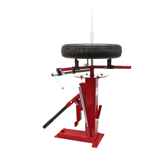
Operation Manual
Manual Tyre Changer
61909
Illustration similar, may vary depending on model
Read and follow the operating instructions and safety information before using for the first time.
Technical changes reserved!
Due to further developments, illustrations, functioning steps and technical data can differ insignific -
antly.
Updating the documentation
If you have suggestions for improvement or have found any irregularities, please contact us.
Advertisement

Related Manuals for WilTec 61909

Summary of Contents for WilTec 61909
- Page 1 Operation Manual Manual Tyre Changer 61909 Illustration similar, may vary depending on model Read and follow the operating instructions and safety information before using for the first time. Technical changes reserved! Due to further developments, illustrations, functioning steps and technical data can differ insignific - antly.
- Page 2 All rights reserved. The WilTec Wildanger Technik GmbH cannot be held accountable for any possible mistakes in this operating manual, nor in the diagrams and figures shown.
- Page 3 1. Attach the jaw frame (19) to the main stand base (4) using screws (22), locknuts (9) and washers (23). 2. Attach the handle holder (7) to the main stand base (4) with a lock pin (8). © by WilTec Wildanger Technik GmbH Item 61909 Page 3 http://www.WilTec.de...
- Page 4 3. Attach the assembly shoe (5) to the handle holder fixture (7) with a screw (6) and locknut (9). 4. Attach the handle (10) to the handle holder (7) using a screw (24) and locknut (12). Tighten all screws and nuts. © by WilTec Wildanger Technik GmbH Item 61909 Page 4 http://www.WilTec.de...
- Page 5 Leave a working area of at least 914 mm on all sides. Mark the drill holes through the base holes and drill four 12.7 mm dia- meter holes. 6. Insert 76.2 mm (3”) concrete anchors into the holes and tighten the anchor nuts. © by WilTec Wildanger Technik GmbH Item 61909 Page 5 http://www.WilTec.de http://www.aoyue.eu 2021-1 http://www.teichtip.de...
- Page 6 Slide clamps are positioned to the correct wheel size as indic- ated by numeric markings on each arm. The pins are inserted on the outside of the terminals. Press the two clamps against the pins. © by WilTec Wildanger Technik GmbH Item 61909 Page 6 http://www.WilTec.de http://www.aoyue.eu...
- Page 7 Disassemble the lower bead in the same way as above. The angle of the tool to the centre post can be varied according to operator height or rim depth, without compromising ease of operation. © by WilTec Wildanger Technik GmbH Item 61909 Page 7 http://www.WilTec.de http://www.aoyue.eu...
- Page 8 Make sure the bead is centred on the rim during the process. In the unlikely event that you will have trouble turning the handle, use a tyre lever. Use a tyre iron to loosen the tire around the point of greatest resistance. Important: Always lubricate the tyre! © by WilTec Wildanger Technik GmbH Item 61909 Page 8 http://www.WilTec.de http://www.aoyue.eu 2021-1 http://www.teichtip.de...
- Page 9 13 Tension rod (with thread) Important notice: The reprint or reproduction, even of excerpts, and any commercial use, even in part of this instructions manual require the written permission of WilTec Wildanger Technik GmbH. © by WilTec Wildanger Technik GmbH...