Advertisement
Quick Links
INTRODUCTION
The FC400 Series Detectors, as supplied, use a common
FC450IB Isolator Base assembly. Guidance on mounting and wir-
ing a FC450IB Isolator Base is given below.
FIXING THE DECTOR BASE
The base may be fixed directly to:
Ø British (fixing centres 50mm) or European (fixing centres
70mm) conduit box;
Ø FC450EMB Euro Mounting Box;
Ø Directly to the ceiling.
DETECTOR LOCATION
The location of each detector should have been determined at the
system design stage in accordance with the site plan. The detec-
tor bases must be mounted in accordance with this plan. If prob-
lems arise then reference to the system designer must be made.
The detector base does not need aligning as the detector LED is
visible through 360°. However, the short circuit indicator needs to
be visible for fault location.
FIXING THE DETECTOR BASE
n TO A CONDUIT BOX
The detector base is to be secured directly to the conduit box with
two M4 pan head steel screws, zinc plated and passivated. The
fixing slot allows the mounting to be fitted to both B.E.S.A. conduit
boxes having fitting points at 50mm centres and European conduit
boxes with fitting points at 70mm centres. For ease of fixing, there
are enlarged holes on the fixing slots, which allows the first fixing
screw to be inserted loosely, the base is then fitted to the screw.
n TO OTHER SURFACES
The detector base is to be secured with two No. 8 x 1 inch pan
head steel screws zinc plated and passivated or equivalent at the
fixing centres shown in Fig. 1.The surface chosen for the mounting
should be flat over the area of the base to ensure a stable fixing.
POSIZIONAMENTO FORI PER VITI
SCREW LOCATING HOLES
MONTAGELÖCHER
FIG. 1 Fixing Dimensions for Detector Base
ENGLISH
n FC450EMB EURO MOUNTING BOX
The European Mounting Box (Fig. 4) is designed to be used with
the FC400 Series detectors in EC countries using 18mm and
21mm cable breakouts.The housing is secured with two No. 8 x 1
inch countersunk zinc plated and passivated steel screws (or
equivalent).The surface chosen for the mounting should be flat
over the area of the underside of the housing to ensure a stable fix-
ing and strong enough to take the weight of the mounting,detector
base and sensor.
DETECTOR BASE WIRING
The detector base is to be wired as shown in Fig. 5. It is recom-
mended that a maximum of two 1.5mm
any one terminal. A remote LED should be wired if specified.
Breakouts are provided at the outer flanges for surface cable
mounting.Take care not overtighten the terminal screws when
connecting the base to the loop wiring.
n MAXIMUM NUMBER OF DEVICES THAT MAY BE CONNECTED.
It is possible to connect a maximum of 32 devices between two loop
isolators (FC450IB o FC410LI), note that in the device counting pro-
cess, each FC410MIO or each FC410SIO adds a double value.
n VERIFYING LOOP WIRING
! WARNING: DO NOT MEGGER LOOP WIRING WITH LINE
ISOLATOR BASES CONNECTED.
The Line Isolator Base is not designed to work with line voltages
above the specified maximum 40V dc. This means that continu-
ity testing of the loop wiring with Line Isolator Bases connected
must be done using a voltage between 20-40V dc. The resis-
tance measurement range on conventional voltmeters use low
voltage only, therefore, the following method can be employed to
confirm loop integrity.A power supply capable of providing 30 -
40V dc with a 300 to 600mA current limit is connected to one end
of the loop (in correct polarity). A voltmeter is connected to the
SEDE CHIAVE DI BLOCCAGGIO
LOCKING KEY SLOT
OPTIONALE SPERRE EINFÜGEN
RIFERIMENTO RIALZATO
RAISED RIB
MARKIERUNG FÜR MELDER IN
BETRIEBSPOSITION
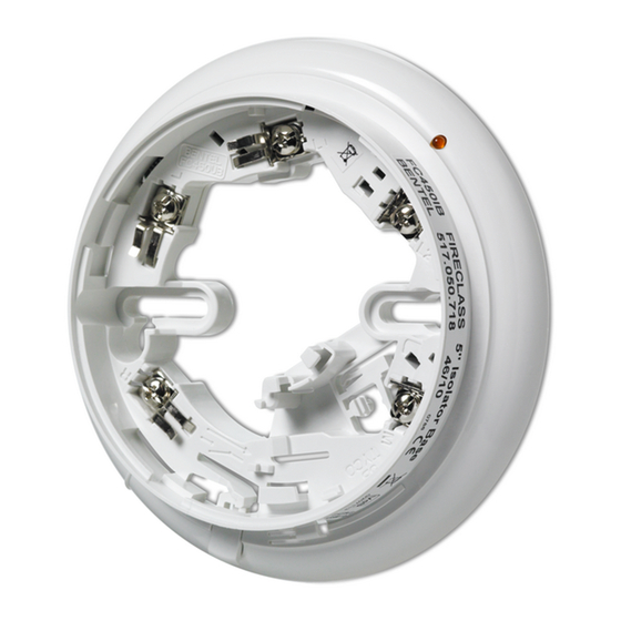
FIG. 2 FC450IB Isolator Base *Patented
2
cables are connected at
INDICATORE DI CORTO
CIRCUITO
SHORT CIRCUIT INDICATOR
LED ZUR
KURZSCHLUSSANZEIGE
CHIAVE DI
BLOCCAGGIO
LOCKING KEY
SPERRE
PERNO PER IL PARCHEGGIO
TEMPORANEO
TEMPORARY PARK
STIFT DRÜCKEN, DANN MELDER IN
PARKPOSITION DREHEN
Advertisement

Related Manuals for Bentel Security FC450IB


Summary of Contents for Bentel Security FC450IB
- Page 1 It is possible to connect a maximum of 32 devices between two loop isolators (FC450IB o FC410LI), note that in the device counting pro- FIXING THE DETECTOR BASE cess, each FC410MIO or each FC410SIO adds a double value.
- Page 2 2) Incorrect Polarity -FC450IB Isolator bases will appear as a short circuit if they are wired with incorrect polarity. +ve IN/OUT 3) Loop Short Circuit - If this occurs between two FC450IB Isola- -ve OUT tor bases, it will isolate that section of the line, which will then -ve IN appear as an open circuit.
- Page 3 FITTING/REMOVAL OF A DETECTOR ORDERING INFORMATION 1) Stick the address number labels to the Address Flag and de- FC450IB: 5" Isolator Base tector. FC450EMB: Euro Mounting Box 2) Fit the Address Flag to the detector as shown in Fig. 7.
Need help?
Do you have a question about the FC450IB and is the answer not in the manual?
Questions and answers