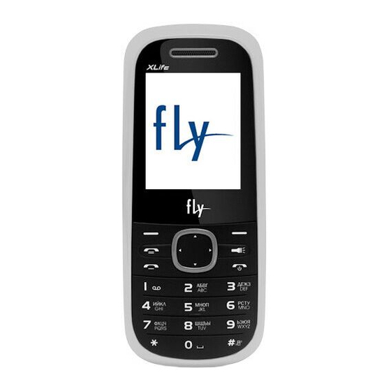
Summary of Contents for FLY DS 110
- Page 1 DS 110 Service Menu Version number: V1.0 Draft Ren Mingwei Auditing Li Xilin Authorize Zhao Gang Date 2010-6-18 Shenzhen IFLY Communication Technology Co., Ltd.
-
Page 2: Table Of Contents
Contents Overview DS 110........................1 1.1 About DS 110 Phone ......................1 1.2 Distribution of the mainboard components ...............2 RF ............................3 2.1 RF Overview ........................3 2.2 Transmit ..........................3 2.3 Receive..........................3 2.4 Common RF Malfunction ....................4 Baseband ..........................15 3.1 Baseband Overview ......................15 3.2 Logic ..........................15 3.3 Power management ......................15... -
Page 3: Overview Ds 110
DS 110 Service menu 1 Overview DS 110 1.1 About DS 110 Phone DS 110 mainboard based platform designed support dual-band which supporting the FM, the mainboard system consists base- band ( CPUMT6223D+EN71PL03280-70CWP) and (AD6548+PARPF88143B). -
Page 4: Distribution Of The Mainboard Components
DS 110 Service menu 1.2 Distribution of the mainboard components... -
Page 5: Rf Overview
DS 110 Service menu 2 RF 2.1 RF Overview RF part mainly consists of transceiver AD6548 (adopts program of near-zero IF receiver, supporting the EGSM / DCS and 26M Crystal as the clock input, integrated clock buffer, LO VCO and TX VCO and regulator, only need for external connections of VBAT / AVDD), PARPF88143B (it supports EGSM / DCS and integrated automatic power control and transceiver switch). -
Page 6: Common Rf Malfunction
DS 110 Service menu 2.4 Common RF Malfunction 2.4.1 Detection and Maintenance Flow Chart of MS Transmit malfunction (No transmit) Connect PC and cell phone with maintenance of line, use the Repair software making mobile phone access to transmit state. - Page 7 DS 110 Service menu IQ signal waveforms of transceiver in transmit state: RF interface spectrum analyzer is as follows: GSM transmit signal...
- Page 8 DS 110 Service menu DCS transmit signal PA-EN waveforms of PA in transmit state: PA-EN...
- Page 9 DS 110 Service menu PA. BAND-SW waveforms: PA.BAND-SW (GSM) PA.BAND-SW (DCS)...
- Page 10 DS 110 Service menu PA Vramp waveforms: Vramp (pcl5) Vramp (pcl 19)
- Page 11 DS 110 Service menu 2.4.3 Detection and Maintenance Flow Chart of MS Receive malfunction No Receive Open Repair Software to connect PC with mobile phone, make the phone access to receiving state, adjust signal generator to corresponding CH, and connect the signal line to phone’s RX_SW.
- Page 12 DS 110 Service menu voltage supply is normal → if normal, Transceiver can be judged of damaged / N: Check PA and the paths ahead ) Signal waveforms refer to the following: Output signal of Signal generator (Input): GSM CH62 channel receives the signal...
- Page 13 DS 110 Service menu IQ signal output pin of Transceiver the state of receiving IQ signal: signal Transceiver received from used access internal register Transceiver. The corresponding waveform is as follows: IQ Signal Frequency-s ynthesizing signal...
- Page 14 DS 110 Service menu 3W(SDATA) 3W(SCLK)...
- Page 15 DS 110 Service menu 3W(LE) 26M clock (can be measured by using the ACCoupling) The AFC (automatic frequency control) from CPU to the crystal oscillator makes crystal oscillator output accurate 26MHZ to Transceiver. 26M Output Input...
- Page 16 DS 110 Service menu VAFC TCXO output(26MHZ)...
-
Page 17: Baseband
3 Baseband 3.1 Baseband Overview DS 110 Baseband consists of CPUMT6223D and Program Memory. UMT6223D baseband, the core device of the mainboard, is responsible for the normal work among various parts of mainboard, such as voice processing, image processing, power management as well as MS communications. -
Page 18: Audio Frequency
DS 110 Service menu Boot process: The normal boot is to press boot key which is that the PWRKEY is being dragged down. Once the boot key is pressed, all LDO are open except VSIM. After VCORE opening RESET timer and timer out, RESET is being pitched up to start the digital baseband chip, that is, UMT6223D starts to run and roll polling its ROWX pin, pitch up its PWRONIN pin, then you can release the boot key. -
Page 19: Baseband Common Malfunction
DS 110 Service menu 3.4.3 Earphone loop Earphone loop includes headset speaker and MIC two-way signal. Check the circuit access situation when there is something abnormal (such as: no sound in headset speaker, Mic invalid, etc.) after inserting the earphone while the headset accessories are good. - Page 20 DS 110 Service menu cut off power supply as soon as possible, and then find the short-circuit point. It may be the abnormal output power supply of a certain circuit that the current is larger than normal (about 30 mA) but not particularly large, at this time should check whethe the valgate of VCORE (1.8V), VDD (2.8V), VADD (2.8 V), VTCXO (2.8V), VRTC (1.5V), VMEM (2.8V) is...
- Page 21 DS 110 Service menu 3.5.3 The signal waveform Chip select signals CS: Screen reset signal LRST:...
- Page 22 DS 110 Service menu Screen Write signal LWR: About the screen, first find the problem whether is mainboard or screen by adopting replacement method, then focus on checking the LCM-CON welding.
-
Page 23: Reference For Maintenance
4.4 Sound trouble DS 110 audio processes in internal CPU, focus on checking the Audio-PA on the issue of free or miscellaneous ring tones. Low ring for checking its solder joints (very small, and easy to cause problems). -
Page 24: Tools
DS 110 Service menu 5 Tools 5.1 Downloading Operation Manual Reference:《手机软件下载操作说明_MTK_售后版》 5.2 Repair tools Operation Manual Reference:《维修软件操作说明_MTK_》 5.3 write SN Operation Manual Reference:《写生产序列号操作说明_MTK_》 5.4 Calibration Operation Manual Reference:《双回路校准系统操作说明_MTK_》 5.5 Testing Operation Manual Reference:《双回路综测系统操作说明_MTK_》 5.6 Function testing Operation Manual 》 Reference:《主板功能测试软件操作说明_MTK 5.7 Detailed maintenance program...


Need help?
Do you have a question about the DS 110 and is the answer not in the manual?
Questions and answers