TEKTELIC Communications Kona Micro User Manual
Outdoor hardened lorawan iot gateway
Hide thumbs
Also See for Kona Micro:
- User manual (23 pages) ,
- Quick start manual (16 pages) ,
- Quick start manual (4 pages)
Table of Contents
Advertisement
Available languages
Available languages
TEKTELIC C
Document type:
Document number:
Document version:
Document Status:
Product name:
Product codes:
TEKTELIC Communications Inc.
th
7657 10
Street NE
Calgary, AB, Canada T2E 8X2
Phone: (403) 338-6900
© 2018 TEKTELIC Communications Inc., All rights reserved.
All products, names and services are trademarks and registered trademarks of their respective companies.
Disclaimer:
Material contained in this document is subject to change without notice. The material herein is solely for
information purposes and does not represent a commitment by TEKTELIC or its representatives. TEKTELIC has
prepared the information contained in this document solely for use by its employees, agents, and customers.
Dissemination of this information and/or concepts to other parties is prohibited without the prior written consent
of TEKTELIC. In no event will TEKTELIC be liable for any incidental or consequential damage in connection with the
furnishing, performance or use of this material.
TEKTELIC reserves the right to revise this publication in accordance with formal change control procedures defined
by TEKTELIC.
OMMUNICATIONS
User Guide
T0005158_UG
0.34
Approved
Kona Micro Outdoor Gateway
See Table 1
I
.
NC
Advertisement
Table of Contents

Related Manuals for TEKTELIC Communications Kona Micro


Summary of Contents for TEKTELIC Communications Kona Micro
- Page 1 Street NE Calgary, AB, Canada T2E 8X2 Phone: (403) 338-6900 © 2018 TEKTELIC Communications Inc., All rights reserved. All products, names and services are trademarks and registered trademarks of their respective companies. Disclaimer: Material contained in this document is subject to change without notice. The material herein is solely for information purposes and does not represent a commitment by TEKTELIC or its representatives.
-
Page 2: Revision History
Updated product descriptions in Table 1 and 4 0.33 Feb 14, 2018 Approved T. Danshin Updated MPE information 0.34 Feb 14, 2018 Approved T. Danshin Updated Radio Compliance Statements Kona Micro Outdoor User Guide T0005158_UG Version 0.34 TEKTELIC Communications Inc. Confidential Page 2 of 32... -
Page 3: Table Of Contents
Précautions de sécurité ....................23 Déballage et inspection ....................24 Équipement pour l'installation ..................24 Montage de la passerelle Kona Micro Outdoor ............. 25 Installation du câble de masse ..................27 Installation directe du câble d'alimentation CC ............. 28 Kona Micro Outdoor User Guide T0005158_UG Version 0.34... - Page 4 Installation du câble Ethernet en cuivre ................ 29 Mise en service et surveillance ....................30 Équipement requis ......................30 Procédure ........................30 déclarations de conformité radio ..................31 Kona Micro Outdoor User Guide T0005158_UG Version 0.34 TEKTELIC Communications Inc. Confidential...
-
Page 5: Product Description
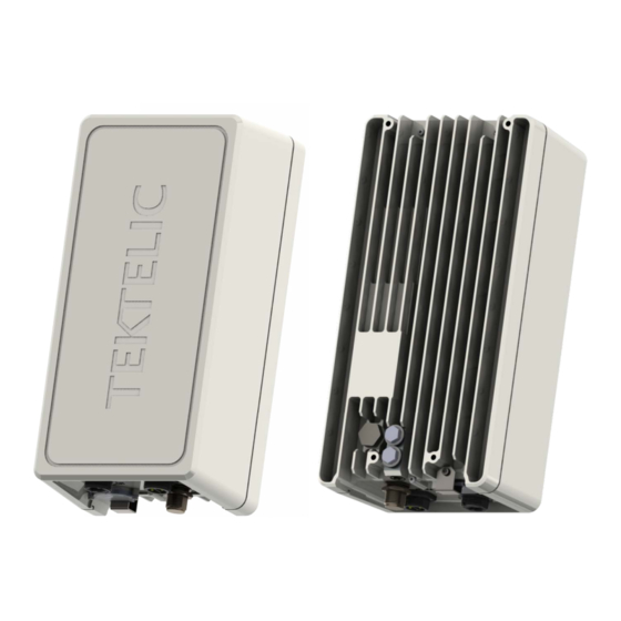
1 Product Description Overview The Kona Micro Outdoor Gateway is an outdoor hardened LoRaWAN IoT gateway that supports the full range of LoRa WAN channels. The Gateway supports one external LoRa antenna, an internal GPS antenna, two power options including direct DC input power or Power over Ethernet (PoE), and two backhaul options including copper Ethernet or 3G/4G wireless. -
Page 6: Physical Interfaces
Figure 1: Kona Micro Outdoor Gateway Common Dimensions Physical Interfaces Figure 2 illustrates the bulkhead layout for the Kona Micro Outdoor Gateway. All models share the same bulkhead layout. Kona Micro Outdoor User Guide T0005158_UG Version 0.34 TEKTELIC Communications Inc. - Page 7 Connector types and their mating connectors are listed in Table 2. Table 2: Kona Micro Outdoor Gateway Interface Connector Types Interface...
-
Page 8: Specifications
Chassis Protective Earth Industry standard 2-hole lug, 1/4 x 0.75” spacing Earth Ground Ground terminal Specifications The Kona Micro Outdoor Gateway specifications are listed in Table 3. Table 3: Kona Micro Outdoor Gateway Specifications Attribute Specification Dimensions 222.2mm (8.7”) wide x 101mm (4.0”) deep x 287.3mm (11.3”) tall Weight 5.1 kg (11.3 lbs) -
Page 9: Installation
• The Kona Micro Outdoor Gateway must be installed in a restricted access location (such that touching of the Gateway by non-service persons is not likely). • The Kona Micro Outdoor Gateway may become hot to the touch during normal operation at elevated ambient temperatures. -
Page 10: Unpacking And Inspection
Kona Micro Outdoor Gateway Mounting Kona Micro Outdoor Gateway is designed to be mounted to a vertical pole or wall using the supplied mounting bracket which attaches at the four screw locations on the back of the module illustrated in Figure 3. - Page 11 Mounting screw location Figure 3: Kona Micro Outdoor Gateway Mounting Bracket Attachment Screw Locations The mounting bracket is a single part that bolts to the back surface of the Gateway using supplied hardware (four M6x1.0 - 14 mm bolts with flat and star lock washers) as illustrated in Figure 4.
- Page 12 2mm gap from the wall surface. 3. Hang the Kona Micro Outdoor Gateway with bracket from the two bolts by inserting the keyhole slots at the top of the bracket onto the 2 bolts and tightening the bolts.
-
Page 13: Ground Cable Installation
The Protective Earth Ground conductor terminated at the double hole lug point is mandatory and must be the first connection made to the Kona Micro Outdoor Gateway during installation. Proper routing and termination of this cable is key to robust lightning withstand performance;... -
Page 14: Direct Dc Power Cable Installation
Figure 5: Chassis Ground Connection Direct DC Power Cable Installation The Kona Micro Outdoor Gateway direct DC feed terminates at a dedicated two pin circular plastic connector (CPC) on the bulkhead. The direct DC power input is isolated from chassis (earth) with the exception of the primary surge suppressors. -
Page 15: Rf Cable Installation
Note that the 3G/4G modem antenna is internal to the Kona Micro Outdoor Gateway. Copper Ethernet Cable Installation The Kona Micro Outdoor Gateway Ethernet port may be used on a temporary basis for commissioning and maintenance or may be permanently connected for backhaul. When the port is not in use, the weatherproof protective cap must be installed. -
Page 16: Commissioning And Monitoring
2. A Cat5 or better Ethernet cable. Procedure Once the DC power and GPS and LoRa RF antenna connections are in place the Kona Micro Outdoor Gateway may be commissioned. 1. Connect an Ethernet cable between the Host PC and the bulkhead copper Ethernet connector (RJ45). -
Page 17: Radio Compliance Statements
Before servicing the product, the antenna(s) or cables, turn off the transmission function or the unit power if you have to get closer than the minimum separation distance. This product must be installed by professional trained RF technicians. Kona Micro Outdoor User Guide T0005158_UG Version 0.34... -
Page 18: Description Du Produit
LoRa externe, une antenne GPS interne, deux options d'alimentation, y compris une alimentation CC directe ou Power over Ethernet (PoE), et deux options backhaul, y compris Ethernet cuivre ou 3G / 4G sans fil. Le tableau 4 présente les modèles Kona Micro Outdoor Gateway actuellement disponibles pour le marché nord-américain.. -
Page 19: Interfaces Physiques
Figure 7: Kona Micro Outdoor Gateway Dimensions communes Interfaces physiques Figure 8 illustre la disposition de la cloison de la Kona Micro Outdoor Gateway. Tous les modèles partagent la même disposition de cloison. Kona Micro Outdoor User Guide T0005158_UG Version 0.34 TEKTELIC Communications Inc. - Page 20 3G / 4G protection Figure 8: Kona Micro Outdoor Gateway Mise en page de cloison Tous les modules d'interconnexion du module Kona Gateway se trouvent sur la cloison inférieure. Les connecteurs RF sont imperméables à l'eau, mais tous les autres connecteurs doivent être terminés avec des connecteurs correspondants ou recouverts avec le capuchon de...
-
Page 21: Spécifications
Terre Terre 1/4 x 0,75 " châssis Spécifications Les spécifications de Kona Micro Outdoor Gateway sont répertoriées dans Table 6. Table 6: Kona Micro Outdoor Gateway Spécifications Attribute Spécifications Dimensions 222.2mm (8.7”) large x 101mm (4.0”) Profond x 287.3mm (11.3”) grand Poids 5.1 kg (11.3 lbs) - Page 22 FCC Pt. 15, RSS-247, EN 301 489-1 Protection contre les Toutes les interfaces sont protégées aux niveaux primaires. surtensions Kona Micro Outdoor User Guide T0005158_UG Version 0.34 TEKTELIC Communications Inc. Confidential Page 22 of 32...
-
Page 23: Installation
La connexion de mise à la terre de protection (c.-à-d. La cosse à deux trous à la masse du châssis) est toujours requise. • Assurez-vous que la connexion à la terre de protection de la passerelle Kona Micro Outdoor Gateway est correctement terminée avant de connecter toute autre interface. -
Page 24: Déballage Et Inspection
à la terre ( s) de l'alimentation DC Kona Micro Outdoor Gateway. • Pour l'entrée d'alimentation CC directe, la broche positive DC doit être à un potentiel positif par rapport à la broche négative DC. Si la polarité est inversée, l'unité ne subira pas de dommages mais ne fonctionnera pas tant que la polarité... -
Page 25: Montage De La Passerelle Kona Micro Outdoor
Montage de la passerelle Kona Micro Outdoor Kona Micro Outdoor Gateway est conçu pour être monté sur un poteau ou un mur vertical en utilisant le support de montage fourni qui se fixe aux quatre emplacements de vis à l'arrière du module illustré... - Page 26 136 kg (300 lb). La zone ci-dessous doit être libre de toute obstruction à l'entrée de câble. La procédure de montage mural Kona Micro Outdoor Gateway est la suivante: 1. Visser le support de montage mural au module de passerelle à l'aide des boulons et des rondelles fournis.
-
Page 27: Installation Du Câble De Masse
électriques locaux et nationaux. Le conducteur de terre de protection terminé au point de cosse à double trou est obligatoire et doit être la première connexion faite à la Kona Micro Outdoor Gateway pendant l'installation. Un routage et une terminaison adéquats de ce câble sont la clé... -
Page 28: Installation Directe Du Câble D'alimentation Cc
Figure 11: Connexion au sol du châssis Installation directe du câble d'alimentation CC L'alimentation CC directe Kona Micro Outdoor Gateway se termine par un connecteur en plastique circulaire à deux broches (CPC) dédié sur la cloison. L'entrée d'alimentation CC directe est isolée du châssis (terre) à... -
Page 29: Installation Du Câble Rf
Scotch, WK-101. Suivez les procédures d'enregistrement décrites par le fournisseur de ce système de bande. Notez que l'antenne du modem 3G / 4G est interne à la Kona Micro Outdoor Gateway. Installation du câble Ethernet en cuivre Le port Ethernet Kona Micro Outdoor Gateway peut être utilisé... -
Page 30: Mise En Service Et Surveillance
7 Mise en service et surveillance Équipement requis L'équipement suivant est requis pour la mise en service et la surveillance de la Kona Micro Outdoor Gateway. 1. Un ordinateur portable fonctionnant sous Windows XP / Vista / 7. 2. Un câble Ethernet Cat5 ou supérieur. -
Page 31: Déclarations De Conformité Radio
à 900 MHz est de 0,5dB ou plus pour 1 porteuse à 28,5dBm ou 2dB ou plus pour 2 porteuses à 30dBm au total . Les antennes doivent être installées à un endroit offrant une distance de séparation d'au moins 13,8 pouces (35 cm) de tout corps humain. Kona Micro Outdoor User Guide T0005158_UG Version 0.34 TEKTELIC Communications Inc. - Page 32 Avant de réparer le produit, l'antenne ou les câbles, désactivez la fonction de transmission ou l'alimentation de l'unité si vous devez vous rapprocher de la distance de séparation minimale. Ce produit doit être installé par des techniciens RF qualifiés. Kona Micro Outdoor User Guide T0005158_UG Version 0.34 TEKTELIC Communications Inc.
Need help?
Do you have a question about the Kona Micro and is the answer not in the manual?
Questions and answers