
Related Manuals for LIGHT MY BRICKS LEGO Book Shop 10270 Lighting Kit


Summary of Contents for LIGHT MY BRICKS LEGO Book Shop 10270 Lighting Kit
-
Page 2: Package Contents
4x White 30cm Bit Lights 2x Pink 30cm Large Bit Lights 1x Blue 30cm Bit Light 2x Green 30cm Bit Lights 1x Light My Bricks Lamp Post 6x Warm White Strip Lights 1x Flicker Effects Board 3x 6-Port Expansion Board... - Page 3 Important things to note: Laying cables in between and underneath bricks Cables can fit in between and underneath LEGO® bricks, plates, and tiles providing they are laid correctly between the LEGO® studs. Do NOT forcefully join LEGO® together around cables; instead ensure they are laying comfortably in between each stud.
- Page 4 Incorrectly inserting the connector can can result in bent pins inside the port or possible overheating of the expansion board when connected. Connecting cable connectors to Strip Lights Take extra care when inserting connectors to ports on the Strip Lights. Connectors can be inserted only one way.
- Page 5 Connecting Micro Cable connectors to Micro Expansion Board Ports Take extra care when inserting the micro connectors to micro ports of Micro Expansion Boards. Connecting Micro Bit Lights to Micro Expansion Boards is similar to connecting lights and cables to Strip Lights. With the expansion board facing up, ensure the side of the connector with the wires exposed is facing down.
- Page 6 OK, Let’s Begin! 1.) Seperate the two buildings, then remove the top two levels of the bluebuilding as we will install lights to this side first. Disconnect the lamp post as well as the following piece behind the flower bed.
- Page 8 Using your LEGO removal tool, disconnect the following tiles and pieces.
- Page 9 Take out the Light My Bricks Lamp Post and connect it to the base plate (without the 2×2 plate underneath it). Lay the cable down towards the building ensuring it’s laid in between studs as shown below, then reconnect the brown 2×4 plate with flower connected, along with the light...
- Page 10 2.) Turn the set around, and disconnect the two side flowers. Take out a Pink 30cm Bit Light and with the LED facing up, place it in the following position in between the brown studs. Reconnect the purple flower piece. Take a Blue 30cm Bit Light and with the LED facing up, place it in the following position in between the brown studs.
- Page 11 Take the remaining Pink 30cm Bit Light and with the LED facing up, place it down in the following position in between the brown studs on the left. Reconnect the blue flower, then ensuring both cables from the Pink Bit Lights are laid in between studs, reconnect the dark grey bricks to secure them in place.
- Page 12 3.) Turn the set around to the front again and reconnect the following bricksand pieces.
- Page 13 Take out the 12-Port Expansion Board and connect the three Bit Lights and the Lamp Post cable to it. Remove the ladder from it’s storage position. Take the USB Power Cable and thread the connector end of the cable through the technic brick hole on the outside of the building on the right side.
- Page 14 Note: If you experience any issues with the lights not working and suspect an issue with a component, please try a different port on the expansion board to verify where the fault lies (with the light or expansion board). To correct any issues with expansion board ports, please view the section addressing expansion board issues on our online troubleshooting guide.
- Page 15 Take out the 50cm Connecting Cable and connect it to a spare port on the expansion board, then thread it through the technic brick hole that leads to the outside of the building (left side). Pull the cable all the way out from the outside. This cable will be used to connect up to the left building (book shop).
- Page 16 If you are connecting both sides of the building together, thread the cable through the black technic pin, then reconnect the pin to the bottom of the building. 5.) We will now light up the first floor starting with the two door lamps. Firstdisconnect the long tile from above the front door, then remove the front door section.
- Page 18 Disassemble each door lamp as shown below, then take out a White 30cm Bit Light and with the cable facing the back of the lamp base, place it over the top of the stud. Secure the Bit Light in place by reconnecting the trans clear brick over the top. Repeat this step to install another White 30cm Bit Light to the other door lamp.
- Page 19 Reconnect the right lamp ensuring you first thread the cable behind and lay it down in between studs. Push down the wall section above, then do the same to reconnect the left lamp. Reconnect the front door section...
- Page 20 6.) Turn this section around so we can access the inside of the front wall. Takethe Bit Light cable from the right door lamp and pull it directly up. Lay the cable around the studs above, then secure it down by reconnecting the long white tile.
- Page 21 Turn this section around to the front and disconnect the following two tiles from the left side. Bring both the door lamp cables across and over the left wall, laying them in between the front two studs. Secure them down by reconnecting the two tiles.
- Page 22 Place this section onto it’s right side, then slightly disconnect the white 1×12 plate from underneath. Pull both cables down the left side of the building and then slip them underneath and in between studs. Secure them in place by reconnecting the white 1×12 plate. Use tape to secure the two cables to the outside wall.
- Page 23 7.) We will now light up the fire place inside the first floor. Disconnect thefollowing tiles, plates, and bricks surrounding the fire place, then disconnect the fire place section as shown below:...
- Page 24 Disconnect the grey bricks from underneath the fire place, then disconnect the trans orange flame piece.
- Page 25 8.) Take a White 15cm Bit Light and seperate the two wires near the LED as shown below. With LED facing forward, place it over the black clip on the right side. Each separated wire should be laid over the left side of this clip. Secure the Bit Light in place by reconnecting the trans orange flame piece.
- Page 26 Ensure the cable is laid underneath and toward the back, then reconnect the grey bricks underneath. Reconnect the fireplace section to the room, then reconnect all the surrounding sections we removed earlier.
- Page 27 9.) Disconnect the following two tiles, then take out a Wireless Connector end with the flat tile. With the cable facing the outside of the building, connect it to the following position. Reconnect the white tile with studs to the left of it. If you have a spare white 1×1 tile, you can connect it to the remaining stud, otherwise, simply leave it as is.
- Page 28 Place the first floor onto it’s left side, then disconnect the white 1×10 plate from underneath. Pull both cables down the outside of the wall and lay them underneath toward the inside. Ensuring the cables are laid in between studs, reconnect the 1×10 plate to secure them both into place.
- Page 29 Use tape to secure both cables down the outside of the wall. 10.) Take out the Flicker Effects Board (FFX) and connect the other end of the White 15cm Bit Light from fireplace to one of the OUT ports. Take a 5cm Connecting Cable and connect one end of it to the IN port on the effects board.
- Page 30 Bring the first floor section over the ground floor and connect the two Bit Lights from the two door lamps to the 12-Port Expansion Board underneath. Connect the Wireless Connector and the other end of the 5cm Connecting Cable from the flicker effects board to the 12-port Expansion Board.
- Page 31 Ensuring all cables are tucked inside, securely reconnect the first floor above the ground floor. Turn ON the Power to test all the lights and effects to the first floor are working OK. The fireplace light should be flickering to give a realistic fire flickering effect.
- Page 32 Note: If you experience any issues with the lights not working and suspect an issue with a component, please try a different port on the expansion board to verify where the fault lies (with the light or expansion board). To correct any issues with expansion board ports, please view the section addressing expansion board issues on our online troubleshooting guide.
- Page 34 Take a White 15cm Bit Light and ensuring the LED is facing down, place it down just in front of the top of the left window frame. Push down the cable into the corner behind, then reconnect the white window roof section. If you look from underneath, you should see the LED peaking out to shine down on the window.
- Page 35 Repeat this step to install another White 15cm Bit Light to the top of the right window frame...
- Page 36 Connect both Bit Lights to a 6-Port Expansion Board. 12.) Place the top floor onto it’s back so we can access underneath of it.Disconnect the following white 1×4 plate on the right side.
- Page 37 Take out a Wireless Connector end with the plate side (studded) and fold the cable over and lay it in between the studs. With the cable facing the inside of the building, connect it underneath the top floor in the following position.
- Page 38 Take out a Warm White Strip Light and using it’s adhesive backing, stick it to the base of a provided LEGO Plate 1×6. Connect the Wireless connector plug to the right port on the Strip Light. Take a 30cm Connecting Cable and connect one end to the left port on the Strip Light.
- Page 39 Connect the Strip Light underneath the top floor in the below position. Ensure the 30cm cable is facing the right side as shown below. Bring the 30cm Connecting Cable across to the left side and over the wireless connector cable. Disconnect the white 1×6 plate from the left side and pull the 30cm cable up the wall.
- Page 40 Tuck in any excess cable from the wireless connector to prevent it from dangling down.
- Page 41 13.) Turn the top floor back over and pull the 30cm Connecting Cable up the left side of the building. Connect it to a spare port on the 6-Port Expansion Board above.
- Page 42 Take a 5cm Connecting Cable and connect one end to the 6-port Expansion Board. Connect the other end of the cable to a new Warm White Strip Light. Turn the top floor around so we are facing the front, then bring the Strip Light over the top and thread it down the following space that leads into the inside.
- Page 44 Note: If you experience any issues with the lights not working and suspect an issue with a component, please try a different port on the expansion board to verify where the fault lies (with the light or expansion board). To correct any issues with expansion board ports, please view the section addressing expansion board issues on our online troubleshooting guide.
- Page 45 Disconnect the following pieces from the right and pull the 30cm Connecting Cable all the way up. Lay the cable toward the inside and in between studs before reconnecting the two dark grey 1×4 plates we removed earlier.
- Page 46 Disconnect the black 2×4 plate and lay the 30cm cable across and in between studs. Reconnect the black 2×4 plate, followed by the larger dark grey plate 2×16 plate.
- Page 47 15.) Turn the set around to the front and lay the window light cables down inbetween studs as shown below, before reconnecting sections over the top.
- Page 48 Tuck the expansion board inside the following space, then lay the remaining excess cables out in between studs. Ensure there are no dangling cables and no components can be seen from the inside the room. Reconnect all the surrounding sections of the roof.
- Page 49 16.) Securely reconnect the top floor to the rest of the building ensuring bothwireless connector contacts are correctly aligned and touching...
- Page 50 Turn ON the power to test all the lights to this building are working OK.
- Page 51 17.) We will now move onto lighting the brown building (Book Shop). Removeall the upper floors and disconnect the tree. Disconnect the following tiles on the top of the ground floor, then disconnect the entire upper wall section above the arches, followed by the lamp and brick section behind it.
- Page 53 18.) Disassemble the lamp as shown below, then take a White 30cm Bit Light and thread the connector end of the cable through the bottom of the trans yellow round brick (large hole) and out the smaller hole. Thread the cable all the way through, then carefully bend the LED so that it faces directly down before pushing it all the way inside the brick.
- Page 54 Reconnect it to the brick section behind, then lay the cable underneath this section and toward the left. Reconnect the lamp to the building ensuring the cable is brought up behind as shown below.
- Page 55 19.) Take the upper wall section we removed earlier and place it onto it’s back sowe can access underneath of it. Take a Green 30cm Bit Light and stick the back of the LED to a provided Adhesive Square. Stick the Bit Light underneath the right arch ensuring the cable is facing the left.
- Page 56 Reconnect this wall section to the front of the building. Ensure the cable from the right arch is laid in between the white brick and front wall as shown below.
- Page 57 Reconnect the 1×2 bricks on each side. If you look closely at the front of the green windows, you should see the Green Bit Light installed to shine down onto the trans green bricks.
- Page 58 20.) Disconnect the stair case floor section from the back of the room, thenlocate the end of the 50cm Connecting Cable from the blue building and thread it through outside of the orange building (technic brick hole). Pull the cable in from the inside of the building underneath the stairs, then thread it up behind the stairs in the corner of the room.
- Page 60 Turn the power ON to test the lamp and window lights are working OK. Note: If you experience any issues with the lights not working and suspect an issue with a component, please try a different port on the expansion board to verify where the fault lies (with the light or expansion board).
- Page 61 Take out a Wireless Connector end (flat tile contact) and with the cable facing the inside of the building, connect it to the following position. Connect the wireless connector cable to a spare port on the 6-Port Expansion Board.
- Page 62 Group the three bit light cables together in between the following studs, then secure them down by reconnecting the 1×2 tile and longer 1×8 tile on both sides. Ensure the three cables are side by side and flat rather than over the top of each other. Disconnect the tile with studs as well as the wireless connector tile, then bring the three cables across toward the back.
- Page 63 Neaten up the cables by bunching them up together, then place the expansion board on top of the book shelf before reconnecting the stair case floor section over the top.
- Page 64 22.) Take the second floor and place it onto it’s back so we can accessunderneath of it. Disconnect the following 1×8 plate from the left side. Take out a Wireless Connector end (plate with stud side) and with the cable facing the inside of the building connect it to the following position.
- Page 66 Connect the other end of the wireless connector to a Warm White Strip Light. Take a 15cm Connecting Cable and connect one end to the Strip Light’s right port. Using it’s adhesive backing, stick the strip light underneath the second floor in the following position. Secure the wireless connector cable by pushing it up inside the plate holes as shown below, then secure the cable by connecting a provided Plate 1×6 over the top.
- Page 67 23.) Connect the other end of the 15cm Connecting Cable from previous step toa new 6-Port Expansion Board. Thread the expansion board up the following space which leads to the inside of the second level. Secure the 15cm cable underneath the following 2×10 plate ensuring the cable is in between studs.
- Page 68 Connect the second floor on top of the ground floor ensuring both the wireless contacts are aligned. Turn ON the power to test the strip light and wireless connectors are working OK.
- Page 69 24.) Remove the second level again and while facing the back right of thissection, disconnect the following tiles. Take out another Wireless Connector End (Flat tile contact) and with the cable facing the inside of the room, connect it to the following position. Take the 1×3 tile and the tile with studs and connect them to new positions as per below:...
- Page 70 Turn the section around so we are facing the inside of the building where the stair case is. Thread the other end of the wireless connector down the space in between the stairs and pull it out from underneath the stair case. Connect this cable to a spare port on the 6-port Expansion board (we pulled up from underneath in previous step).
- Page 71 25.) Disconnect the floor lamp and disassemble it as per below: Take a White 30cm Bit Light and with the LED facing down, place it over the top stud of the trans clear brick. Secure the Bit Light in place by reconnecting the gold tile with clip over the top, then reconnect it to the lamp post.
- Page 72 Disconnect the following tiles and wall section, then lay the Bit Light cable from the lamp over the studs. Reconnect the wall section we removed over the top.
- Page 73 From the other side of the wall, pull the lamp cable up and lay it over the wall. Secure it in place by reconnecting the 1×4 tile over the top.
- Page 74 26.) Turn this section around to the front and disconnect the following tilesfrom the front. Connect the other end of the lamp cable to a spare port on the 6-port expansion board inside. Stick 2x Adhesive Squares to the back of the expansion board and mount it inside the second floor in the following position.
- Page 75 Take the two cables and pull them up the front corner of the room. Secure them on top of the room by laying them in between studs. Reconnect the following two tiles over the top.
- Page 76 Continue to lay the excess cable from the floor lamp in between studs toward the right side. Reconnect tiles over the top as you go.
- Page 77 Disconnect the following tiles and lay the remaining cable in between studs underneath before reconnecting the tiles over the top.
- Page 78 Reconnect the second floor to the ground floor again ensuring the two wireless connector contacts are aligned. Turn ON the power to test the floor lamp light is working OK. Note: If you experience any issues with the lights not working and suspect an issue with a component, please try a different port on the expansion board to verify where the fault lies (with the light or expansion board).
- Page 79 Connect the other end of the wireless connector to a new Warm White Strip Light. Connect a 5cm Connecting Cable to the other end of the strip light, then using it’s adhesive stick the Strip Light underneath the top floor in the following position. Ensure the 5cm cable is facing left.
- Page 80 28.) Connect the other end of the 5cm Connecting Cable to a new Warm White Strip Light. Take the remaining 15cm Connecting Cable and connect it to the other end of the Strip Light, then using it’s adhesive backing, stick this strip light to the following position underneath the top floor.
- Page 81 Secure the wireless connector cable by laying it in between studs and connecting a provided LEGO Plate 1×6 over the top. Secure any remaining excess cable underneath the dark grey 1×10 plate. Thread the other end of the 15cm Connecting Cable up the following space that leads into the top floor.
- Page 82 29.) Disconnect the roof section as well as the following angled brick on theright side. Pull the 15cm Connecting Cable up and lay it around the following stud before reconnecting the angled brick over it.
- Page 83 Connect the cable to the remaining Warm White Strip Light. Using it’s adhesive backing, stick the strip light underneath the roof section we disconnected earlier in the following position. Bring the cable up the corner and lay it behind the following studs before securely reconnecting the roof.
- Page 84 Turn this section around to the front and secure any excess cable underneath the following tiles.
- Page 85 30.) Securely reconnect the top floor to the rest of the building, ensuring thetwo wireless connectors are correctly aligned. Turn the power ON to test all lights to the building are working OK before reconnecting the back wall.
- Page 86 Note: If you experience any issues with the lights not working and suspect an issue with a component, please try a different port on the expansion board to verify where the fault lies (with the light or expansion board). To correct any issues with expansion board ports, please view the section addressing expansion board issues on our online troubleshooting guide.
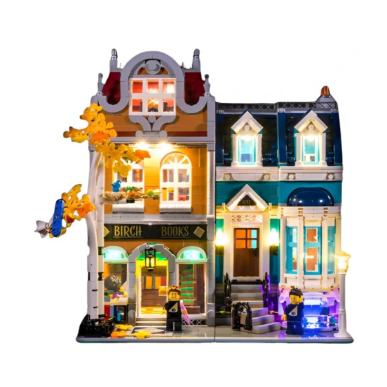
- Page 87 This finally completes installation of the Light My Bricks Book Shop 10270 Light Kit. We thank you for purchasing this product and hope you ENJOY!
Need help?
Do you have a question about the LEGO Book Shop 10270 Lighting Kit and is the answer not in the manual?
Questions and answers