Advertisement
Quick Links
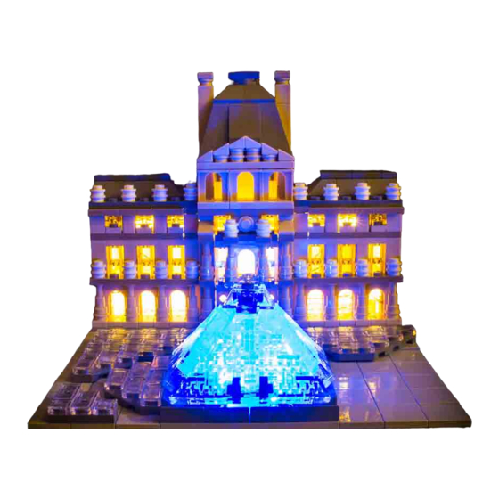
Light My Bricks : The Louvre LED Lighting Kit
Here is the instruction document for the Lego Louvre LED lighting kit. Please read and
follow the steps carefully to ensure this lighting kit is installed properly.
Package Contents:
2 x LED Strip Lights
2 x Blue Bit Lights
1 x 6 Port Expansion Board
1 x Standard Battery Pack (requires 3 x AA batteries not included)
Connecting Cables
1 x 5cm
1 x 15cm
Extra Lego Pieces
2x 1 x 6 Plate
Any colour will do as the plates are hidden inside the model. These are attached to
the LED Strip Lights.
Advertisement

Related Manuals for LIGHT MY BRICKS The Louvre LED Lighting Kit


Summary of Contents for LIGHT MY BRICKS The Louvre LED Lighting Kit
- Page 1 Light My Bricks : The Louvre LED Lighting Kit Here is the instruction document for the Lego Louvre LED lighting kit. Please read and follow the steps carefully to ensure this lighting kit is installed properly. Package Contents: 2 x LED Strip Lights ...
- Page 2 Important things to note: Laying cables in between and underneath bricks Cables can fit in between and underneath LEGO® bricks, plates, and tiles providing they are laid correctly between the LEGO® studs. Do NOT forcefully join LEGO® together around cables; instead ensure they are laying comfortably in between each stud.
- Page 3 CAUTION: Forcing LEGO® to connect over a cable can result in damaging the cable and light. Connecting cable connectors to Strip Lights Take extra care when inserting connectors to ports on the Strip Lights. Connectors can be inserted only one way. With the Strip Light facing up, ensure the side of the connector with the wires exposed is facing down.
- Page 4 Connecting cable connectors to Expansion Boards Take extra care when inserting connectors to ports of Expansion Boards. Connectors can be inserted only one way. With the expansion board facing up, look for the soldered “=” symbol on the left side of the port. The connector side with the wires exposed should be facing toward the soldered “=”...
- Page 5 WARNING: Incorrectly inserting the connector can result in bent pins inside the port or possible overheating of the expansion board when connected. Installing Bit Lights under LEGO® bricks and plates. When installing Bit Lights under LEGO® pieces, ensure they are placed the correct way up (Yellow LED component exposed).
- Page 7 OK, Let’s Begin!
- Page 8 Instructions for installing this kit We will start by installing the two blue bit lights under the pyramid at the front of the model and run the wires from these lights towards the back and then inside the building. Then we will connect the two lights to the 6 port expansion board inside the building.
- Page 9 Remove the 1 x 2 tiles and the transparent round bricks left from under the pyramid structure. What you should see now is a 6 x 6 area of dark grey bricks where the pyramid was as seen in the picture below.
- Page 10 Now we need to remove three of the “water” pieces on the left hand side of the model.
- Page 11 Remove the two 1 x 2 plates and the sloped tiles fixed to them. You want the highest one from the left hand side and the lowest one from the right hand side.
- Page 12 We want to make a path to run our wires from inside the pyramid towards the left and right side of the model. Remove the bottom most 6 tiles on the right hand side of the model. I have started with the two immediately next to the plate and slope tile we removed.
- Page 13 Remove the remaining four tiles so that you can see the studs from the plates underneath going all the way to the edge of the model.
- Page 14 We want to do the same sort of thing on the left hand side but higher up where the gap is from the 1 x 2 plate and slope plate we removed earlier. Looking from there to the left, we want to remove the 2 x 4 plate, the 1 x 2 plate, the 1 x 2 tile and the remaining four 2 x 2 tiles.
- Page 15 Your model should now look like the picture above. You’ll see that I have also removed the 1 x 8 plate from the left edge of the model. Go ahead and remove all three from both sides of the model (6 in total). OK……let’s put some lights in! These two bit lights will end up sitting reasonably flat and facing upwards.
- Page 16 When you press you finger on the wire close to the LED end, the LED should rest somewhere near the middle of the four studs in the lower left hand corner. It doesn’t need to be perfect, but if you can get close to this, things will be easier later on.
- Page 17 Now we are going to put the 1 x 2 plate and sloped tile back and secure the wire under it. Position the wire in the centre of the two studs that the plate goes on top of and hold it in place with your finger.
- Page 18 Put the 1 x 2 plate and sloped tile back in place.
- Page 19 If your LED and wire look like the picture below, then you have done well and we are ready to move on.
- Page 20 We are going to follow roughly the same method for the LED that comes in from the left hand side. Run the wire in, remembering to curve the end near the LED and we want it to sit roughly in the middle of the top four studs in the top right hand corner.
- Page 21 Centre the wire where it comes out of the pyramid section and hold it in place with your finger. Put the 1 x 2 plate and sloped tile back in place securing the wire underneath it.
- Page 22 Back to the right hand side. Gently pull the wire on the right hand side so that it comes straight out and stays in the middle of the studs. You only need to apply enough pressure to keep it straight.
- Page 23 Replace the six tiles concealing the wire in the middle.
- Page 24 Now back to the left hand side! Gently pull the wire on the left hand side so that it comes straight out and stays in the middle of the studs. You only need to apply enough pressure to keep it straight.
- Page 25 Replace the tiles and plates concealing the wires between the studs.
- Page 26 Now we are going to run the wires towards the back of the model and feed them in to the building. I’m going to detail one side of the building but you exactly the same thing for each side.
- Page 27 Gently pull the wire along the edge of the model (on top of the exposed black studs) until it runs straight towards the back.
- Page 28 When the 1 x 8 tile (shown above) is replaced, it will pull the wire down and back towards the front. Allow the wire to do this. We want the wire to rest in between the studs and plates next to them. Gently place the 1 x 8 black tile back where it came from.
- Page 29 Notice that the wire nearest the plate you just put on sits nice and low next to the studs? That is ideal for the next section as well. Gently place the second 1 x 8 tile back where it belongs. Repeat the steps above for the other side of the model.
- Page 30 We need to remove all three roof sections. Looking down on the model, I place my index and middle finger across the brown plates with the lip on them. With my thumb positioned at the back applying gentle downward pressure, I lift from the front like I’m peeling the roof off.
- Page 31 Repeat the above steps for the roof section on the left hand side.
- Page 32 Now remove the centre roof section. I like to pry the back section away from the large left and right panels at the back. Give it a bit of a jiggle if you need to and lift up. The front of this model is not particularly secure so it should come away quite easily.
- Page 34 Time to feed the bit light wires into the sides of the building. I’m going to detail one side of the building but you exactly the same thing for each side.
- Page 35 There are a couple of options here. the quickest and simplest method is to feed the wire in behind the pillar, behind the window piece and through to the back.
- Page 37 You’ll notice that this method does leave some wire clearly visible. If this doesn’t bother you, then this is the way to go! Alternatively, there is a 1 x 4 tan brick and a 1 x 1 tan brick near the bottom of the wall. We are going to feed the wire in between these two bricks.
- Page 38 Feed the end of the wire into the gap between the bricks and gently pull it through to from the other side of the wall. Let the wall rest back in place but do not push it down and lock it in to position just yet.
- Page 39 We need to fit the last 1 x 8 tile now. Similarly to the first one, when we put this tile back on, the wire may get pulled back and down. We want to allow this to easily happen. Lift the building wall again and gently replace the 1 x 8 tile.
- Page 40 From the inside of the wall, gently pull the wire so that it lies against the side of the 1 x 1 tan brick. Move the wall back into place and let it rest in position. If your wires are in between the tan bricks, secure the wall back into place.
- Page 41 Repeat these steps for the other side of the model. Grab the 6 port expansion board.
- Page 42 Connect both of the plug ends of the Blue bit light wires to this expansion board.
- Page 43 With both wires connected and the two remaining rear panels removed, your model should resemble the picture below.
- Page 44 Find your 15cm connecting cable and connect it to the 6 port expansion board.
- Page 45 Find your two strip lights and attach them to 1 x 6 plates as seen in the “IMPORTANT Things to Note” section at the beginning of this guide. (1 x 6 plates are not included but can be purchased separately if you don’t already have your own)
- Page 46 With your remaining 5cm connecting cable, connect the two LED Strip Lights. Now you can connect one of the LED strip lights to the 15cm connecting cable.
- Page 47 Connect the battery pack to the 6 port expansion board.
- Page 48 Grab the centrepiece from the building and put it in front of you where you can work with...
- Page 49 Attach the 1 x 6 plates with the strip lights attached exactly as shown in the picture.
- Page 50 Ok…..let’s put her back together! If you want to conceal the battery pack inside the model, now is the time to position it inside the building. Sit the battery pack inside the building making sure the switch is facing you and rest the centrepiece in place (don’t secure it just yet).
- Page 51 If you have any connecting cable sticking out, move it around so that it stays inside the building.
- Page 52 Replace the rear panels remembering that they partly sit underneath the centrepiece.
- Page 53 Push the battery pack towards the centre of the model where it won’t obstruct the light coming out the front sides.
- Page 54 Push the centrepiece down to secure it and the side panels. Then attach each side roof.
- Page 56 Turn the model around so we can finish the front.
- Page 57 Replace the trans-clear round bricks that came from the centre of the pyramid.
- Page 58 The wires from the lights should run naturally close to the round bricks. Gently replace two of the 1 x 2 grey tiles which will hold the wires in place.
- Page 59 With both tiles in place the LEDs should be facing up and in approx. the centre of the four studs in each corner. Place the other two 1 x 2 plates around the round bricks.
- Page 60 Replace the three “water” pieces back on the left hand side of the pyramid.
- Page 61 Replace the 4 sides of the pyramid and the centrepiece.
- Page 62 Congratulations — y ou’re finished! Now you can switch it on and enjoy!
-
Page 63: Notes On Battery Packs
NOTES ON BATTERY PACKS: If you choose to conceal the battery pack within the model, you will need to access it by removing the rear left panel to switch it on and off again. - Page 64 Another option is to leave the battery pack outside of the model. The bricks may not close neatly around battery pack wires depending on their placement. If you don’t like how this looks, you may choose to remove a 1 x 1 brick and run the wire through the hole.
- Page 65 If you have the standard battery pack as seen in the photo and choose to conceal it within the model, you may notice that one side of the building appears darker (because of the size of the battery pack).
- Page 66 If you centre the battery pack inside the model, this will reduce the darkening effect greatly.
Need help?
Do you have a question about the The Louvre LED Lighting Kit and is the answer not in the manual?
Questions and answers