Advertisement
Quick Links
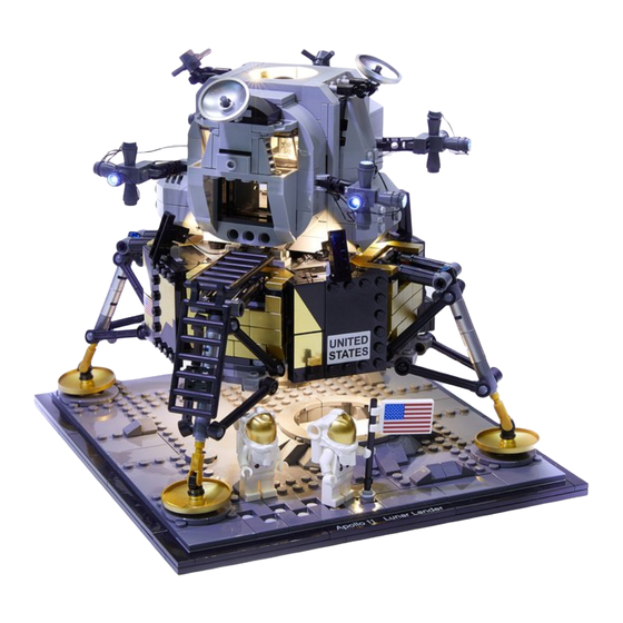
Light My Bricks: LEGO NASA Apollo 11 Lunar
Lander 10266 Lighting Kit
Light My Bricks LEGO
Apollo 11 Lunar Lander (10266) LED light kit.
NASA
online troubleshooting
guide.
Please note: This page lists instructions for the LED light kit only. If you are
wishing to purchase the Light My Bricks LEGO NASA Apollo 11 Lunar Lander
Advertisement

Related Manuals for LIGHT MY BRICKS LEGO NASA Apollo 11 Lunar Lander


Summary of Contents for LIGHT MY BRICKS LEGO NASA Apollo 11 Lunar Lander
- Page 1 Apollo 11 Lunar Lander (10266) LED light kit. NASA online troubleshooting guide. Please note: This page lists instructions for the LED light kit only. If you are wishing to purchase the Light My Bricks LEGO NASA Apollo 11 Lunar Lander...
-
Page 2: Package Contents
Package Contents: 8x Cool White 30cm Bit Lights 1x Blue 30cm Bit Light 1x Orange 30cm Bit Light 2x 6-Port Expansion Boards 2x Flicker Effects Boards 2x 5cm Connecting Cables 2x Flat Battery Packs (requires 3x CR2032 Batteries each) 2x 3M Adhesive Squares LEGO Pieces: Important things to note:... - Page 3 CAUTION: Forcing LEGO® to connect over a cable can result in damaging the cable and light. Connecting cable connectors to Expansion Boards Take extra care when inserting connectors to ports of Expansion Boards. Connectors can be inserted only one way. With the expansion board facing up, look for the soldered “=” symbol on the left side of the port.
- Page 4 Incorrectly inserting the connector can can result in bent pins inside the port or possible overheating of the expansion board when connected. Connecting cable connectors to Strip Lights Take extra care when inserting connectors to ports on the Strip Lights. Connectors can be inserted only one way.
- Page 5 Installing Bit Lights under LEGO® bricks and plates. When installing Bit Lights under LEGO® pieces, ensure they are placed the correct way up (Yellow LED component exposed). You can either place them directly on top of LEGO® studs or in between.
- Page 6 OK, Let’s Begin! We will start with lighting the bottom section of the Lander. First disconnectthe upper shuttle, then remove the bottom section from the base and turn it onto it’s side. Disconnect the Jet section as per below:...
- Page 7 Take the Jet section and slightly disconnect the part above by pulling it up, then push the technic pin out slightly by approx. 5mm. Take the Blue 30cm Bit Light and loop the cable as shown below: Place the loop of the cable around the technic bar’s head, then pull the other end of the cable so that the cable...
- Page 8 tightens the loop securely around the technic bar. Push the bar back in to secure the cable in between. Thread the other end of the cable through the following space of the frame above, then pull the cable all the way out from the other side.
- Page 9 Push the section above back down, then push the cable down into the corner of the inside of the Jet section. Fold down the cable on the outside.
- Page 10 Thread the Bit Light cable through the technic plate hole underneath thelower section of the Lander, pull the cable all the way out from above, then reconnect the Jet section. Connect the Blue Bit Light to one of the OUT ports on a Flicker Effects Board. Take a 5cm Connecting Cable and connect it to the IN port on the Flicker Effects Board, then connect the other end of the cable to a 6-Port Expansion Board.
- Page 11 Turn the Lander around to the back and disconnect the following section inthe middle. Pull the two grey plates out to allow us to disconnect the dark grey plate behind.
- Page 12 Take a Flat Battery Pack and insert 2x new CR2032 batteries to it. Thread the battery pack cable through the following space that leads inside the Lander and pull it out from the inside, then connect it to the 6-Port Expansion Board.
- Page 13 Turn the Battery Pack ON to test the blue jet light is working OK and flickering! Note: If you experience any issues with the lights not working and suspect an issue with a component, please try a different port on the expansion board to verify where the fault lies (with the light or expansion board).
- Page 14 Reconnect the black wall section, then take 2x Adhesive Squares and stick them to the back of the Battery Pack. Mount the battery pack to the outside of the Lander in the below position (mount to the flat surface of the black plates):...
- Page 15 Secure the battery pack cable in between pieces as shown below:...
- Page 16 Turn the bottom section of the Lander around to the front, then onto it’sback side so we can access underneath. Take a Cool White 30cm Bit Light, and with the cable facing down, place the Bit Light underneath the Lander inside the hole underneath the black 2×3 plate, as per below.
- Page 17 Using this same method, install another Cool White 30cm Bit Light to the right side, securing it in place by connecting another Trans Clear Plate w Rounded Bottom 2×2 over the top. Thread the Bit Light cable through a different hole as shown below:...
- Page 18 Push both cables down behind the edge of the black 2×3 plate to prevent them from dangling later on.
- Page 19 Take another Cool White 30cm Bit Light and with the cable facing up, place it over the lower hole underneath the black 2×3 plate on the bottom left, as per below. Secure the Bit Light in place by connecting another provided Trans Clear Plate w Rounded Bottom 2×2 over the top. Thread the cable all the way through the same hole we threaded the first Cool White Bit Light through.
- Page 20 Repeat this process to install another Cool White 30cm Bit Light to the bottom right side, securing it in place by connecting another Trans Clear Plate w Rounded Bottom 2×2 over the top. Thread the Bit Light cable all the way through the same hole we did for the second Cool White Bit Light we installed in previous step.
- Page 21 Turn the Lander back over, then connect all four Bit Light cables to the 6-Port Expansion Board. Turn the Flat Battery Pack located on the back ON to test the lights are all working OK, then place the Lander back onto the base plate.
- Page 22 Note: If you experience any issues with the lights not working and suspect an issue with a component, please try a different port on the expansion board to verify where the fault lies (with the light or expansion board). To correct any issues with expansion board ports, please view the section addressing expansion board issues on our online troubleshooting guide.
- Page 23 Take the four cables from the Cool White Bit Lights and pull them up and twist them around each other. This will help prevent them from dangling down underneath. Neatly tuck the bunched up cables into the spaces on the side, then tuck the expansion board and flicker effects board into the far sides as shown below:...
- Page 24 Ensure there are not dangling cables visible from underneath.
- Page 25 10.) We will now install lights to the upper shuttle of the Lander. Firstdisconnect the side sections, then disconnect the Jet piece from underneath as shown below: Take a Orange 30cm Bit Light and thread the connector side of the cable through the centre hole underneath of the Jet piece.
- Page 26 Place the LED in the centre of the 4 studs, then reconnect the Jet piece underneath the upper section of the Lander. Ensure the other end of the cable is facing down and in between the two studs of the Jet section. Take the remaining Trans Clear Plate w Rounded Bottom 2×2 and connect it over the Bit Light as shown below.
- Page 27 11.) Turn this middle section around to the other side, then disconnect thesection with the two grey tiles running horizontally. Pull the Bit Light cable up and lay them in between studs before reconnecting the section with the grey tiles over it.
- Page 28 Connect the Orange Bit Light to one of the OUT ports on a new Flicker Effects Board. Take a 5cm Connecting Cable and connect it to the IN port on the Flicker Effects Board, then connect the other end of the cable to a new 6-Port Expansion Board.
- Page 29 Take another Flat Battery Pack and insert 2x new CR2032 batteries to it. Connect the battery pack cable to the 6-Port Expansion Board, then turn the battery pack ON to test the Jet light is on and flickering OK. Note: If you experience any issues with the lights not working and suspect an issue with a component, please try a different port on the expansion board to verify where the fault lies (with the light or expansion board).
- Page 30 12.) Take the right section of the upper shuttle and place it onto it’s back.Disconnect the sections from underneath as shown below:...
- Page 31 13.) Take a Cool White 30cm Bit Light and with the cable facing the left, place it underneath the the following piece. Secure the Bit Light in place by connecting a provided Trans Clear Round Plate 1×1 over the top (Connecting the stud side of the plate inside the piece above)
- Page 32 Disconnect the grey pieces from the black technic clip, then reconnect them ensuring you feed the cable underneath and out the front as shown below: Disconnect the black technic clip from the grey clip, then reconnect it ensuring the cable is fed through and out underneath as shown below:...
- Page 33 Disconnect the following pieces from the front: 14.) Follow the previous step to Install another Cool White 30cm Bit Light to the left side, securing it in place with another provided Trans Clear Round Plate 1×1. Disconnect and Reconnect the arm sections in order to feed and secure the cables through the gaps.
- Page 35 15.) Lay both cables toward the middle then up before reconnecting thefollowing 1×4 brick over the top of the cables ensuring both cables are in between studs. Tuck the middle section of the cables up the inside of the shuttle as per below:...
- Page 36 Reconnect the sections underneath as well as the two tiles on the top. 16.) Bring this right section closer to the middle section, then connect the two Bit Light cables to the 6-Port Expansion Board in the middle section. Turn the Battery Pack ON to test the two lights are working OK.
- Page 37 Note: If you experience any issues with the lights not working and suspect an issue with a component, please try a different port on the expansion board to verify where the fault lies (with the light or expansion board). To correct any issues with expansion board ports, please view the section addressing expansion board issues on our online troubleshooting guide.
- Page 39 17.) Take the left side of the upper shuttle and disconnect the bottom sectionsas shown below:...
- Page 40 With the front of this section facing up, take a Cool White 30cm Bit Light and following the same method used to install lights to the right section (step 13), install it to the right side of this section. Use a provided Trans Clear Round Plate 1×1 to secure the Bit Light in place. 18.) Continue following step 13 to disconnect the arm sections to feed andsecure the cable through the clips toward the middle.
- Page 41 Lay the cable underneath this section in between studs, before reconnecting the lower right section. Bring the the cable out toward the front of this section.
- Page 42 19.) Repeat the previous two steps to install the remaining Cool White 30cm Bit Light to the left side, securing it in place with the remaining provided Trans Clear Round Plate 1×1.
- Page 43 Lay the cable underneath this section in between studs before reconnecting the lower left section over the top. 20.) With the front of this section still facing toward you, flip this section upsidedown (so the yellow control handles are facing you). Lay both cables in between studs in each corner before reconnecting the middle lower section.
- Page 44 Take the two Bit Light cables and connect them to the remaining ports on the...
- Page 45 6-Port Expansion Board inside the middle compartment. Turn the Flat Battery Pack ON to test all lights in the upper shuttle are working OK. Note: If you experience any issues with the lights not working and suspect an issue with a component, please try a different port on the expansion board to verify where the fault lies (with the light or expansion board).
- Page 47 Place the battery pack inside the cabin ensuring the cable is neatly placed underneath and the battery pack switch is facing out.
Need help?
Do you have a question about the LEGO NASA Apollo 11 Lunar Lander and is the answer not in the manual?
Questions and answers