GEM 533 eSyStep Operating Instructions Manual
Motorized globe valve positioner (code s0)
Hide thumbs
Also See for 533 eSyStep:
- Operating instructions manual (55 pages) ,
- Operating instructions manual (52 pages) ,
- Operating instructions manual (64 pages)

Related Manuals for GEM 533 eSyStep


Summary of Contents for GEM 533 eSyStep
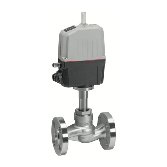
- Page 1 GEMÜ 533 eSyStep Positioner (Code S0) Motorized globe valve Operating instructions further information webcode: GW-533...
- Page 2 All rights including copyrights or industrial property rights are expressly reserved. Keep the document for future reference. © GEMÜ Gebr. Müller Apparatebau GmbH & Co. KG 08.10.2020 GEMÜ 533 2 / 61 www.gemu-group.com Positioner (Code S0)
-
Page 3: Table Of Contents
LED symbols ............Definition of terms ..........Warning notes ............. 2 Safety information ............ 3 Product description ........... 4 GEMÜ CONEXO ............5 Correct use ............... 6 Order data ..............7 Technical data ............10 8 Dimensions ............... 16 9 Manufacturer's information ........20 Delivery .............. -
Page 4: General Information
Working medium The medium that flows through the GEMÜ product. Diaphragm size Hot plant components! Uniform seat size of GEMÜ diaphragm valves for different nominal sizes. 1.5 Warning notes 2 Safety information Wherever possible, warning notes are organised according to... -
Page 5: Product Description
Valve body 1.4408, EN-GJS-400-18- turer first. LT (GGG 40.3) In cases of uncertainty: 15. Consult the nearest GEMÜ sales office. www.gemu-group.com 5 / 61 GEMÜ 533 Positioner (Code S0) -
Page 6: Gemü Conexo
3.3 Description WARNING The GEMÜ 533 is a motorized 2/2-way globe valve. The eSyStep electric actuator is available as ON/OFF or with integ- Improper use of the product rated positioner. The valve spindle is sealed by a self-adjust- ▶... - Page 7 5 Correct use The product is not intended for use in potentially explosive areas. ● Use the product in accordance with the technical data. www.gemu-group.com 7 / 61 GEMÜ 533 Positioner (Code S0)
-
Page 8: Order Data
EN-GJS-400-18-LT (GGG 40.3) 6 Seat seal Code PTFE PTFE, glass fibre reinforced 1.4404 7 Voltage/frequency Code 24 V DC 8 Control module Code Positioner Positioner, configured for emergency power supply module (NC) GEMÜ 533 8 / 61 www.gemu-group.com Positioner (Code S0) - Page 9 Kv value table. 10 Actuator version Actuator size 0 11 Type of design Without 12 CONEXO Integrated RFID chip for electronic identification and traceability www.gemu-group.com 9 / 61 GEMÜ 533 Positioner (Code S0)
-
Page 10: Technical Data
For max. operating pressures the pressure / temperature correlation must be observed. Higher operating pressures on request Leakage rate: Control valve Seat seal Standard Test procedure Leakage rate Test medium Metal DIN EN 60534-4 PTFE, FKM, EPDM DIN EN 60534-4 GEMÜ 533 10 / 61 www.gemu-group.com Positioner (Code S0) - Page 11 25.0 RS481 RS501 10.0 RS482 RS502 15.0 RS483 RS503 10.0 RS484 RS504 10.0 RS485 RS505 16.0 RS486 RS506 25.0 RS488 RS508 40.0 RS490 RS510 Kv values in m³/h Pressures in bar www.gemu-group.com 11 / 61 GEMÜ 533 Positioner (Code S0)
- Page 12 2006/42/EU EMC Directive: 2014/30/EU Interference resistance: DIN EN 61000-6-2 DIN EN 61326-1 (industrial processes) Interference emission: DIN EN 61000-6-4 (Sep. 2011) Interference emission class: Class A Interference emission group: Group 1 GEMÜ 533 12 / 61 www.gemu-group.com Positioner (Code S0)
- Page 13 ▶ With reduced forces, higher duty cycles and/or higher ambient temperatures are possible. At higher force settings the duty cycle and/or ambient temperature is reduced. ▶ IO-Link: Index 0x90 - Subindex 2 - Force www.gemu-group.com 13 / 61 GEMÜ 533 Positioner (Code S0)
- Page 14 0/4 - 20 mA; 0 - 10 V (function selectable via IO-Link) Output type: active Accuracy: ≤ ±1% of full flow Temperature drift: ≤ ±0.1% / 10°K Load resistor: ≤ 750 kΩ Resolution: 12 bit Short-circuit proof: GEMÜ 533 14 / 61 www.gemu-group.com Positioner (Code S0)
- Page 15 20 ms (eSyStep positioner, code S0) Vendor-ID: Device-ID: 1906801 (eSyStep positioner, code S0), Product-ID: eSyStep Positioner (code S0) ISDU support: SIO operation: IO-Link specification: V1.1 IODD files can be downloaded via https://ioddfinder.io-link.com/ or www.gemu-group.com. www.gemu-group.com 15 / 61 GEMÜ 533 Positioner (Code S0)
-
Page 16: Dimensions
32.5 70.0 82.0 150.0 202.0 384.8 252.8 32.5 70.0 82.0 150.0 202.0 389.0 257.0 32.5 70.0 82.0 150.0 202.0 400.5 268.5 32.5 70.0 82.0 150.0 202.0 408.5 276.5 Dimensions in mm GEMÜ 533 16 / 61 www.gemu-group.com Positioner (Code S0) - Page 17 Code 8: Flange EN 1092, PN 16, form B, face-to-face dimension FTF EN 558 series 1, ISO 5752, basic series 1 2) Valve body material Code 37: 1.4408, investment casting Code 90: EN-GJS-400-18-LT (GGG 40.3) www.gemu-group.com 17 / 61 GEMÜ 533 Positioner (Code S0)
- Page 18 Code 48: Flange JIS 20K, face-to-face dimension FTF EN 558 series 10, ASME/ANSI B16.10 table 1, column 16, DN 50 drilled to JIS 10K 2) Valve body material Code 37: 1.4408, investment casting GEMÜ 533 18 / 61 www.gemu-group.com Positioner (Code S0)
- Page 19 Code 39: Flange ANSI Class 125/150 RF, face-to-face dimension FTF EN 558 series 1, ISO 5752, basic series 1 2) Valve body material Code 37: 1.4408, investment casting Code 90: EN-GJS-400-18-LT (GGG 40.3) www.gemu-group.com 19 / 61 GEMÜ 533 Positioner (Code S0)
-
Page 20: Manufacturer's Information
Provide precautionary measures against exceeding the ● 4. Do not store solvents, chemicals, acids, fuels or similar maximum permitted pressures caused by pressure fluids in the same room as GEMÜ products and their spare surges (water hammer). parts. CAUTION Use as step. -
Page 21: Installation Position
The installation position of the product is optional. 10.3 Installation with flanged connections Fig. 1: Flanged connection NOTICE Sealing material ▶ The sealing material is not included in the scope of deliv- ery. Only use appropriate sealing material. ● www.gemu-group.com 21 / 61 GEMÜ 533 Positioner (Code S0) -
Page 22: Electrical Connection
Digital input 1 Digital input 2 Digital input/output Digital output, IO-Link n. c. Connection X2 5-pin M12 plug, A-coded Signal name I+/U+, set value input I-/U-, set value input I+/U+, actual value output GEMÜ 533 22 / 61 www.gemu-group.com Positioner (Code S0) - Page 23 Off/Open/Closed/Safe/On/Ini- Safe/On tialization Digital input/output Open/Closed/Error/Error and Error Error warning/Initialization Digital output Open/Closed/Error/Error and Closed Closed warning Analogue input 4–20 mA/0–20 mA/0–10 V 4–20 mA 4–20 mA Analogue output 4–20 mA/0–20 mA/0–10 V 4–20 mA 4–20 mA www.gemu-group.com 23 / 61 GEMÜ 533 Positioner (Code S0)
-
Page 24: Specific Data Io-Link (Pin 6)
12.1 Operation on IO-Link 12.1.1 Operation on PLC as a 24 V device The motorized actuator GEMÜ eSyStep can be operated directly in a PLC control unit without limitations. Technical data of the product and of PLC must be complied with. - Page 25 During IO-Link operation, pin 6 cannot be evaluated by the PLC control unit as an output signal. Item Name eSyStep PLC with supply voltage USB IO-Link Master USB interface Mains plug – laptop www.gemu-group.com 25 / 61 GEMÜ 533 Positioner (Code S0)
- Page 26 ● Connect pin 4 (CQ) IO-Link master with pin 6 of the product. Do not connect (pin 3) L- IO-Link master. (L-) Item Name eSyStep B1 and B2 Supply voltages USB IO-Link Master GEMÜ 533 26 / 61 www.gemu-group.com Positioner (Code S0)
-
Page 27: Process Data
1 → Process valve in Closed position Operating mode 0 → Normal operation 1 → Initialization mode Valve position analog 8 … 23 Position of the valve in the range 0 … 1000 www.gemu-group.com 27 / 61 GEMÜ 533 Positioner (Code S0) -
Page 28: Parameter Overview
Read out device "eSyStep name Positioner" 0x13 Product ID Read out product "eSyStep Positioner" 0x15 Serial number Read out serial "XXXXXXXX/YYYY" number 0x16 Hardware revision Read out hardware "Rev. XX/XX" version GEMÜ 533 28 / 61 www.gemu-group.com Positioner (Code S0) - Page 29 2 → Output error 3 → Output error & warning 0x4E Logic digital inputs / Input 1 Configure logical 0 → Active high outputs digital input 1 1 → Active low www.gemu-group.com 29 / 61 GEMÜ 533 Positioner (Code S0)
- Page 30 0 … 4095 Min. CLOSED end posi- 0 … 4095 tion 0x60 Analog values Potentiometer Analog value po- 0 … 4095 tentiometer Supply voltage Analog value sup- 0 … 4095 ply voltage GEMÜ 533 30 / 61 www.gemu-group.com Positioner (Code S0)
- Page 31 (0 to 4.0 mA) I max Determine max- 200 to 220 imum current input (20.0 to 22.0 mA) U max Determine max- 100 to 110 imum current input (10.0 to 11.0 V) www.gemu-group.com 31 / 61 GEMÜ 533 Positioner (Code S0)
- Page 32 1 → 4 to 20 mA 2 → 0 to 10 V Min. Determine min- 0 to Max imum signal out- (0.0% to Max) Determine max- 1000 Min to 1000 imum signal out- (Min to 100%) GEMÜ 533 32 / 61 www.gemu-group.com Positioner (Code S0)
-
Page 33: Parameter
0x03 1 byte Data storage index Data Storage Cmd UIntegerT8 1 byte State Property UIntegerT8 4 bytes Data Storage Size UIntegerT32 4 bytes Parameter Check- UIntegerT32 Index List Octet- bytes StringT www.gemu-group.com 33 / 61 GEMÜ 533 Positioner (Code S0) - Page 34 Profile ArrayT 0x8000 Characteristics 0x8002 0x8003 0x8100 Description of parameter values Index name Parameter Values Description Profile Characteristics 0x8000 Device identification objects 0x8002 Process data mapping 0x8003 Diagnostics 0x8100 External identification GEMÜ 533 34 / 61 www.gemu-group.com Positioner (Code S0)
- Page 35 The device name can be read out in ASCII format with the Product name parameter. Off- Access Length Index name Parameter Type Values Rights 0x12 18 byte Product name StringT "eSyStep Positioner" www.gemu-group.com 35 / 61 GEMÜ 533 Positioner (Code S0)
- Page 36 A text with 32 characters can be stored in the device with the Application specific tag parameter. For example, installation location, function, installation date, etc. Off- Access Length Index name Parameter Type Values Rights 0x18 Application StringT „**************** " bytes specific tag GEMÜ 533 36 / 61 www.gemu-group.com Positioner (Code S0)
- Page 37 Parameter Type Values Rights 0x25 39 byte Detailed Device ArrayT See chapter 12.5 Events Status Description of parameter values Index name Parameter Values Description Detailed Device Status See chapter 12.5 Events www.gemu-group.com 37 / 61 GEMÜ 533 Positioner (Code S0)
- Page 38 The functions of the digital inputs can be configured with the Function digital inputs parameter. Off- Access Lengt Index name Parameter Type Default Values Rights 0x4B 3 bits Function digital Input 1 uint:8 inputs 3 bits Input 2 uint:8 GEMÜ 533 38 / 61 www.gemu-group.com Positioner (Code S0)
- Page 39 The safety position is defined by the parameter Error Action (index 0x4F (see "Error Action'"). (Init) Input can be used as an initialization input. www.gemu-group.com 39 / 61 GEMÜ 533 Positioner (Code S0)
- Page 40 (Output Error & Warning) Output error and warnings. (Input Init) Configure input/output as initialization input. Type in- / output (Push-Pull) Configure output as Push-Pull. (NPN) Configure output as NPN. (PNP) Configure output as PNP. GEMÜ 533 40 / 61 www.gemu-group.com Positioner (Code S0)
- Page 41 (Active high) Input 2 not inversed. (Active low) Input 2 inversed. Input / output 1 (Active high) Input/output not inversed. (Active low) Input/output inversed. Output 2 (Active high) Output not inversed. (Active low) Output inversed. www.gemu-group.com 41 / 61 GEMÜ 533 Positioner (Code S0)
- Page 42 (Open) Actuator moves to the OPEN position in case of an error. (Close) Actuator moves to the CLOSED position in case of an error. Error time 1 … 1000 Determine delay time between error detection and error message. GEMÜ 533 42 / 61 www.gemu-group.com Positioner (Code S0)
- Page 43 Operating mode for OPEN/CLOSE control activated. IO-Link process data (Disabled) Use of IO-Link process data (see “Process data“, page 27) is deactivated. (Enabled) Use of IO-Link process data (see “Process data“, page 27) is activated. www.gemu-group.com 43 / 61 GEMÜ 533 Positioner (Code S0)
- Page 44 Initialized positions Open 0 … 4092 Analog value valve position OPEN Close 0 … 4092 Analog value valve position CLOSED Stroke 0 … 4092 Analog value stroke (difference between OPEN and CLOSED). GEMÜ 533 44 / 61 www.gemu-group.com Positioner (Code S0)
- Page 45 Read out current analog value of the supply voltage. Temperature 0 … 4095 Read out current analog value of the temperature sensor. Set value (W) 0 … 4095 Read out current analog value of the set value. www.gemu-group.com 45 / 61 GEMÜ 533 Positioner (Code S0)
- Page 46 1 … 6 Set the force during initialization. Preset at the factory depending on the valve type. Force settings Actuator size Setting parameter Force AG0 and AG1 Minimum force Maximum force GEMÜ 533 46 / 61 www.gemu-group.com Positioner (Code S0)
- Page 47 Open tight 800 … 1000 Set the sealing function valve position OPEN. (80.0 … 100.0 Close tight 0 … 200 Set the sealing function valve position CLOSED. (0 … 20.0 %) www.gemu-group.com 47 / 61 GEMÜ 533 Positioner (Code S0)
- Page 48 Set the stroke limiter of the control range in valve position 1000 OPEN. (Min Pos to 100.0%) Min pos 0 to Max Pos Set the stroke limiter of the control range in valve position (0.0% to Max CLOSED. Pos) GEMÜ 533 48 / 61 www.gemu-group.com Positioner (Code S0)
- Page 49 U max 100 to 110 Determine maximum value of the voltage input. If the set (10.0 to 11.0 V) value is exceeded, the message "Set value too high" is issued. www.gemu-group.com 49 / 61 GEMÜ 533 Positioner (Code S0)
-
Page 50: Events
Event Description Possible cause Troubleshooting Device Hardware Fault The event occurs when a Fault in valve position Contact GEMÜ Support 0x5000 hardware fault is detected. detection. Parameter can no longer be read when switching the device on. Motor Unable To Move... - Page 51 Error when replacing a "Open" direction. diaphragm (stroke of the valve in incorrect area). Actuator has been fitted on the valve incorrectly (stroke of the valve in the incorrect area). www.gemu-group.com 51 / 61 GEMÜ 533 Positioner (Code S0)
-
Page 52: Operation
ð OPEN and CLOSED LEDs flash alternately. 2. Valve automatically moves into the OPEN position. 3. Valve automatically moves into the CLOSED position. 4. Initialization mode is automatically ended. 5. The end positions are set. GEMÜ 533 52 / 61 www.gemu-group.com Positioner (Code S0) -
Page 53: Inspection And Maintenance
5. Clean all parts of contamination (do not damage parts dur- 5. Depressurize the plant or plant component. ing cleaning). 6. Actuate GEMÜ products which are always in the same po- 6. Check parts for potential damage, replace if necessary sition four times a year. -
Page 54: Replacing The Seals
DN 40 150 Nm DN 50 200 Nm 5. Move the actuator A to the closed position. 6. With the valve fully assembled, check the function and tightness. 7. Carry out initialisation. GEMÜ 533 54 / 61 www.gemu-group.com Positioner (Code S0) -
Page 55: Troubleshooting
Emergency power operation, OPEN position Emergency power operation, CLOSED position Emergency power operation, position unknown Set value too small Set value too high Maintenance required, OPEN position Maintenance required, CLOSED position Maintenance required, position unknown www.gemu-group.com 55 / 61 GEMÜ 533 Positioner (Code S0) - Page 56 Valve body / actuator damaged Replace valve body/actuator Body of the GEMÜ product is leaking Body of the GEMÜ product is faulty or Check the body of the GEMÜ product for corroded potential damage, replace body if...
-
Page 57: Removal From Piping
3. Disassemble the product. Observe warning notes and goods can be processed only when this note is completed. If safety information. no return delivery note is included with the product, GEMÜ cannot process credits or repair work but will dispose of the 17 Disposal goods at the operator's expense. -
Page 58: Declaration Of Incorporation According To 2006/42/Ec (Machinery Directive)
19 Declaration of Incorporation according to 2006/42/EC (Machinery Directive) Declaration of Incorporation according to the EC Machinery Directive 2006/42/EC, Annex II, 1.B for partly completed machinery GEMÜ Gebr. Müller Apparatebau GmbH & Co. KG Fritz-Müller-Straße 6-8 74653 Ingelfingen-Criesbach, Germany declare that the following product Make: GEMÜ... -
Page 59: Declaration Of Conformity According To 2014/68/Eu (Pressure Equipment Directive)
EN 1983, AD 2000 Note for products with a nominal size ≤ DN 25: The products are developed and produced according to GEMÜ process instructions and quality standards which comply with the requirements of ISO 9001 and ISO 14001. According to Article 4, Paragraph 3 of the Pressure Equipment Directive 2014/68/EU these products must not be identified by a CE-label. -
Page 60: Declaration Of Conformity According To 2014/30/Eu (Emc Directive)
21 Declaration of conformity according to 2014/30/EU (EMC Directive) EU Declaration of Conformity in accordance with 2014/30/EU (EMC Directive) GEMÜ Gebr. Müller Apparatebau GmbH & Co. KG Fritz-Müller-Straße 6-8 74653 Ingelfingen-Criesbach, Germany declare that the product listed below complies with the safety requirements of the EMC Directive 2014/30/EU. - Page 61 Subject to alteration GEMÜ Gebr. Müller Apparatebau GmbH & Co. KG *88668387* Fritz-Müller-Straße 6-8, 74653 Ingelfingen-Criesbach, Germany 10.2020 | 88668387 Phone +49 (0)7940 123-0 · info@gemue.de www.gemu-group.com...
Need help?
Do you have a question about the 533 eSyStep and is the answer not in the manual?
Questions and answers