
Related Manuals for Hypertherm EcoSift


Summary of Contents for Hypertherm EcoSift
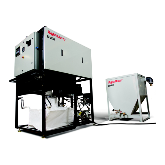
- Page 1 EcoSift ™ Waterjet abrasive recycling system Operator Manual 809500 | Revision 0 | English...
- Page 2 All other trademarks are the property of their respective holders. One of Hypertherm's long-standing core values is a focus on minimizing our impact on the environment. Doing so is critical to our, and our customers', success. We are always striving to become better environmental stewards; it is a process we care deeply about.
- Page 3 EcoSift Operator Manual 809500 Revision 0 English Original instructions November 2017 Hypertherm Inc. Hanover, NH 03755 USA www.hypertherm.com...
- Page 4 México, D.F. C.P. 01780 (Technical Service Email) 52 55 5681 8109 Tel 52 55 5683 2127 Fax South America & Central America: Hypertherm Brasil Ltda. Soporte.Tecnico@hypertherm.com (Technical Service Email) Rua Bras Cubas, 231 – Jardim Maia Guarulhos, SP – Brasil...
-
Page 5: Table Of Contents
Voltage ......................................41 Waste hopper ..................................41 4 Operation ............................43 Safety ........................................43 Operation panel ....................................44 Turn ON the EcoSift ..................................47 Examine the machine before operation ..........................47 Prepare the EcoSift ................................48 Start the EcoSift ..................................49 Turn OFF the EcoSift ..................................50 Routine stop .....................................50 Stop for maintenance, repair, or at the end of the day ....................51... - Page 6 Monitor the dryer box ammeter ............................90 Replace a dryer box component or remove a blockage ....................91 Replace the dryer blower air filter ............................93 Examine the diaphragm pumps ..............................94 Repair a diaphragm pump ..............................96 Start the EcoSift after maintenance ............................109 EcoSift Operator Manual 809500...
- Page 7 9 Installation ...........................137 Safety ......................................137 Buyer obligations ..................................138 Planning ......................................138 Location ....................................139 Requirements ..................................140 Receive and unpack the equipment ............................142 EcoSift unit ....................................142 EcoSift hopper ..................................142 Parts ......................................143 Waste hopper ..................................145 Install the EcoSift ..................................146 Special tools ..................................146 EcoSift Operator Manual 809500...
- Page 8 Connect the electric power ............................... 162 Install the abrasive collection components ........................166 Do the first startup ..................................168 Examine the EcoSift before operation ..........................168 Prepare the EcoSift ................................169 Start the EcoSift ................................... 170 10 Technical drawings ........................173...
-
Page 9: Warranty
if the system has been operated contrary to Hypertherm’s instructions or stated limits of rated and normal use. For full details of the manufacturer’s warranty, refer to the conditions of sale provided when the product was purchased. - Page 10 Warranty Disclaimer Product information contained in this manual is believed to be reliable as of the date of publication. The content in this manual may contain technical inaccuracies or typographical errors. This manual can be changed or updated without notice. SC-10 Safety and compliance...
-
Page 11: Product Stewardship
European directives and standards. Only those versions of Hypertherm products with a CE mark on or near the data plate have been tested for compliance with the applicable European directives, such as the Low Voltage Directive, the Electromagnetic Compatibility Directive, the Pressure Equipment Directive, and the Machinery Directive. -
Page 12: Declaration Of Conformity
Product stewardship Declaration of conformity SC-12 Safety and compliance... - Page 13 CE mark on the data plate. Countries that require a CE mark or have compulsory electromagnetic compatibility regulations must use CE versions of Hypertherm products with the CE mark on the data plate. These may include, but are not limited to: ...
- Page 14 Product stewardship SC-14 Safety and compliance...
-
Page 15: Environmental Stewardship
Particle emission and wastewater quality Hypertherm does not manufacture or supply the materials that are cut and has no knowledge whether the particles released from materials that are cut can pose a physical hazard or health risk. Consult with your supplier or other technical advisor for guidance concerning the properties of the material you cut using a Hypertherm product. - Page 16 Environmental stewardship SC-16 Safety and compliance...
-
Page 17: Safety
Failure to obey safety instructions can cause personal injury or damage to equipment. WARNING Keep this manual near the system. The manual is intended to familiarize the user with the EcoSift and its parts, safe operation, and maintenance. Copies of the manuals may accompany the product in electronic and printed formats. To see an electronic copy of a manual in all languages available for each manual: 1. -
Page 18: User Training
User training Foreseeable misuse Do not use this system in a manner not specified by Hypertherm or for a purpose for which it is not intended. Such use may impair the protections provided by the system. Users must read and understand these instructions before installing, operating, or doing maintenance on this system. -
Page 19: Lifting Hazards
• Misuse of lifting equipment can cause the load to become unstable, which can cause property damage, personal injury, or death. Damaged machinery and parts Do not operate the EcoSift when it is damaged or broken. WARNING Use the emergency stop knob to stop the system immediately. Refer to on page 51. -
Page 20: Personal Protective Equipment
Safety Personal protective equipment Personal protective equipment is important for keeping operators, those working in the area near the machinery, and maintenance personnel safe. Obey your company’s safety program in all aspects of safety, to include the use of personal protective equipment. Wear approved personal protective equipment such as goggles, gloves, and respirators when operating or working near this machinery. -
Page 21: Symbols And Marks
Symbols and marks Information and hazard symbols Some symbols in these tables can be applicable to other products. These symbols are used in this manual or on the system. This symbol identifies an imminently hazardous situation, which, if not prevented, will cause serious injuries or death. - Page 22 Symbols and marks HARMFUL Skin sensitization or irritation Eye irritation HEALTH HAZARD Respiratory sensitization This symbol identifies a potentially hazardous situation, which, if not prevented, can cause minor or moderate injuries or property damage. CAUTION CAUTION Hot surfaces present a burn hazard. Do not touch hot surfaces. CAUTION Lifting hazard –...
- Page 23 Protective conductor terminal This terminal is intended for connection to an external conductor for protection against electrical shock in the case of a fault. AIR-FLOW The arrow indicates the direction of airflow. SHIPPING BRACKETS REMOVE BEFORE OPERATION. REPLACE BEFORE SHIPPING. This symbol identifies tools or materials that are required or recommended for a procedure.
- Page 24 European directives and standards. Only those versions of Hypertherm products with a CE mark on or near the data plate have been tested for compliance with the applicable European directives, such as the Low Voltage Directive, the Electromagnetic Compatibility Directive, the Pressure Equipment Directive, and the Machinery Directive.
- Page 25 These symbols are on the waste hopper. This symbol identifies a potentially hazardous situation, which, if not prevented, can cause serious injuries or death. WARNING Refer to the manual. Read and understand all of the safety guidelines in this manual. Crush hazard Stay clear of the hopper while transporting or dumping.
- Page 26 Symbols and marks Do not stand below the bag. Do not open the bottom of the bag while standing below the bag. Do not cut the bottom of the bag while standing below the bag. Avoid sharp edges HANDLING RECOMMENDATIONS HANDLING RECOMMENDATIONS Use extensions with a crane to lift the bag.
-
Page 27: Terminology
Any source of electric, mechanical, hydraulic, pneumatic, chemical, thermal, or other energy Extreme pressure ( ) is a property used to describe grease; this grease resists mechanical breakdown, oxidation, and heat EcoSift Operator Manual 809500... - Page 28 A kilopascal (kPa) is a unit of pressure: 1 kPa equals 0.01 bar or 0.15 psi or 1,000 N/m lbf∙ft pound force inch, the torque created by 1 pound of force applied at a 1-foot distance from a perpendicular pivot point; 1 lbf∙ft equals 12 lbf∙in or 1.36 N∙m EcoSift Operator Manual 809500...
- Page 29 An original equipment manufacturer ( ) of machines that are sold directly to end users overvoltage category (installation category) A standard that describes how much transient voltage the equipment can tolerate; refer to Electric power page 133. EcoSift Operator Manual 809500...
- Page 30 The system turns off without completing an established sequence of actions; this can occur when power is lost or when the mergency stop knob is pushed. Refer to normal shutdown union A 3-part fitting that is similar to a coupling, designed to join 2 pipes or tubes for easy assembly and disassembly EcoSift Operator Manual 809500...
- Page 31 Terminology Volts of alternating current valve A device used to control the rate of flow in a pipe or a tube Volts of direct current EcoSift Operator Manual 809500...
- Page 32 Terminology EcoSift Operator Manual 809500...
-
Page 33: Product Description
• The system is designed for use with 80-mesh abrasive. • Do not use the EcoSift to recycle abrasive that has been used to cut at 6,205 bar (90,000 psi). The abrasive removal and recycling process produces 2 types of materials. -
Page 34: Overview
5 Agitation pump 17 Dust collector 6 EcoSift hopper 18 Waste hopper 7 Waste water to the cutting table Abrasive 8 Abrasive pump Water 9 Distribution head 10 Primary screen Waste water 11 Dryer box Hot air EcoSift Operator Manual 809500... - Page 35 Product description The EcoSift hopper (6) holds wet used abrasive. A pump (8) pulls that wet abrasive into the EcoSift unit. The distribution head (9) deposits the wet abrasive onto the primary screen (10). Clean water from the nozzles on the distribution head flushes away debris and small particles that are too small for recycling.
-
Page 36: Ecosift Hopper
Waste hopper Refer to item 18 on page 34. Water and abrasive flow from the EcoSift to a waste tube that empties into the waste hopper. Water returns to the cutting table through the overflow tube. 1 Waste tube 2 Overflow tube The waste hopper tilts easily for cleaning. -
Page 37: Waste-Abrasive Collection Bag (Optional)
The bag is for one-time use only. EcoSift unit Work that requires opening the electrical enclosure or removing covers or panels from the EcoSift unit must be done only by an approved technician. WARNING The covers on the left, right, and back of the unit are removable. -
Page 38: Operation Panel
Product description Operation panel Controls for the EcoSift are on the outside of the electrical enclosure. 1 Scale display 4 Dryer box ammeter 2 Operator interface 5 Emergency stop knob 3 Electrical disconnect knob Refer to on page 43 for detailed descriptions of the controls. -
Page 39: Diaphragm Pumps
A mixture of water and abrasive in the EcoSift hopper moves from the hopper to the EcoSift unit. Abrasive pump The abrasive pump pulls water and abrasive from the bottom of the EcoSift hopper and moves it to the top of the EcoSift unit. The mixture goes through the distribution head and onto the primary screen. - Page 40 Product description EcoSift Operator Manual 809500...
-
Page 41: Options
Options Voltage The EcoSift is available in 2 voltage configurations. Refer to the data plate or the technical drawings for the voltage of this equipment. Refer to the section, which starts on page 173. Technical drawings 50 Hz 60 Hz... - Page 42 Options EcoSift Operator Manual 809500...
-
Page 43: Operation
Operation The EcoSift can only recycle garnet and aluminum oxide abrasive. The system is designed for use with 80-mesh abrasive. Do not use the EcoSift to recycle abrasive that has been used to cut at 6,205 bar (90,000 psi). Safety Refer to the manual. -
Page 44: Operation Panel
Operator interface The operator interface is the controller for the EcoSift. Screens on the operator interface show the system status and let the operator start and stop the unit. It also shows failure information, lets the operator to test various components, notifies the operator that the recycled-abrasive collection bag is full, and monitors the time a consumable part has been in use. - Page 45 • All personnel in an area where energy-control procedures are used must receive training regarding the energy-control procedure and the prohibition against removing a lock-out device. The electrical disconnect knob disconnects electric power to the unit motor and controls. RESET ELEASE EcoSift Operator Manual 809500...
- Page 46 Dryer box ammeter Turn the knob to this position to open the electrical enclosure or to reset the primary breaker. ESET This disconnects electric power to the EcoSift unit. The electrical panel is energized. This indicates that the breaker is open.
-
Page 47: Turn On The Ecosift
Make sure that the abrasive collection bags and the waste container are not full. If the EcoSift turns off because of a fault, correct the fault. Refer to on page 119. Warnings and faults ... -
Page 48: Prepare The Ecosift
1. Turn the compressed air, the supply water, and the electric power supply. 2. Turn the electrical disconnect knob to The operator interface turns on. The EcoSift is ready to operate when the home screen (RUNNING PAGE) status is READY. -
Page 49: Start The Ecosift
If there is too much abrasive on the primary screen, lower the abrasive pump pressure until the quantity of abrasive on the primary screen is sufficient. 6. Examine the system for leaks or damage. 7. Examine the pipes, the hoses, the fittings, and the connections for leaks, deterioration, or damage. EcoSift Operator Manual 809500... -
Page 50: Turn Off The Ecosift
On the home screen (RUNNING PAGE), touch to turn the EcoSift. The EcoSift does a normal shutdown. 1. The abrasive pump turns off. 2. The feed pump water hoses are cleared. 3. After 10 minutes, the heating elements turn off. -
Page 51: Stop For Maintenance, Repair, Or At The End Of The Day
Stop for maintenance, repair, or at the end of the day Turn the pump valves when stopping the EcoSift for longer than 1 day. Abrasive can flow from the EcoSift hopper into the pump hoses. Dried abrasive is not easily cleaned from the hoses. -
Page 52: Operator Interface Screens
This shows the temperature of the heating elements inside the dryer box. The optimal temperature is between 137.8°C (280°F) and 160.0°C (320°F). Information only STATUS This shows the status of the EcoSift. Refer to on page 52. STATUS opens the MENU screen. -
Page 53: Menu Screen
Component on/off screens This opens the DUST COLLECTOR BLOWER screen. DUST COLLECTOR Refer to on page 57. Component on/off screens This opens the AGITION PUMP screen. AGITATION PUMP Refer to on page 57. Component on/off screens EcoSift Operator Manual 809500... - Page 54 Refer to on page 63. OPTIONS screen This opens the I/O STATUS screen. I/O STATUS Refer to on page 56. I/O STATUS screen This opens the TIME screen. TIMERS Refer to on page 60. TIME screen EcoSift Operator Manual 809500...
-
Page 55: Abrasive Recycle Rate Trend Screen
Information only Time (minutes) This shows the minutes elapsed since starting the machine. The number sets to 0 when the EcoSift turns off. Recycle Rate Information only The blue line on the graph shows the rate of abrasive in kilograms (or US pounds) per hour that is delivered to the recycled-abrasive collection bag. -
Page 56: Faults Screen
The specified controller input or output is on. opens the home screen (RUNNING PAGE). MAIN Refer to on page 52. Home screen (RUNNING PAGE) opens the MENU screen. MENU Refer to on page 53. MENU screen EcoSift Operator Manual 809500... -
Page 57: Component On/Off Screens
Refer to on page 53. MENU screen HEATING ELEMENTS screen PRIMARY SHAKER screen DRYER BLOWER screen DUST COLLECTOR BLOWER screen AGITATION PUMP screen FEED PUMP screen Refer to page 59 for more information. ABRASIVE PUMP screen EcoSift Operator Manual 809500... - Page 58 Operation RINSE WATER screen FAULT LIGHT screen ALARM HORN screen For testing For testing For testing This turns the water from the This turns the fault indicator This turns the alarm sprayer head beacon EcoSift Operator Manual 809500...
-
Page 59: Feed Pump Screen
The indicator is green when the component is on. Touch this to turn the component opens the home screen (RUNNING PAGE). MAIN Refer to on page 52. Home screen (RUNNING PAGE) opens the MENU screen. MENU Refer to on page 53. MENU screen EcoSift Operator Manual 809500... -
Page 60: Time Screen
SYSTEM RUN TIME Information only System Run Time This shows how long in hours and minutes that the machine has been operating. opens the home screen (RUNNING PAGE). MAIN Refer to on page 52. Home screen (RUNNING PAGE) EcoSift Operator Manual 809500... -
Page 61: Consumables Screens
Primary Screen Life screen Hopper Wear Plate Life screen The screens show how long in hours and minutes that the primary screen and the EcoSift hopper wear plate have been in use. Use these to toggle between the PRIMARY SCREEN LIFE screen and the HOPPER WEAR PLATE LIFE screen. - Page 62 A bar shows a visual representation of the component’s operation time in hours Enter the maximum time setpoint on the OPTIONS screen. Refer to page 63. opens the home screen (RUNNING PAGE). MAIN Refer to on page 52. Home screen (RUNNING PAGE) EcoSift Operator Manual 809500...
-
Page 63: Options Screen
The maximum weight that the bag can hold is 454 kg (1,000 lb). opens the home screen (RUNNING PAGE). MAIN Refer to on page 52. Home screen (RUNNING PAGE) opens the MENU screen. MENU Refer to on page 53. MENU screen EcoSift Operator Manual 809500... -
Page 64: Scale Weight/Process Temperature Screen
Information only Time (hrs) This shows the hours ( ) elapsed since starting the machine. The number sets to 0 when the EcoSift turns off. TEMP Information only Temp This shows the temperature of the heating elements inside the dryer box. -
Page 65: Preventive Maintenance
Preventive maintenance Hypertherm recommends preventive and scheduled maintenance for this system. High-quality systems that are maintained on a schedule lasts longer than systems that are not maintained regularly. Maintenance includes, but is not limited to, adjustments, cleaning, lubrication, repairs, and replacement of parts. -
Page 66: Safety
Obey all safety requirements and applicable safety laws and regulations. Coordinate preventive maintenance and repair activities with operations and safety staff. Examine and clean the system regularly. Refer to the on page 68. Preventive maintenance schedule Make repairs immediately. EcoSift Operator Manual 809500... -
Page 67: Training
Refer to on page 111. Preventive maintenance records Keep the work area clean and free of fluid spills. Use buckets or other containers in areas where water can spill during maintenance or repair procedures. EcoSift Operator Manual 809500... -
Page 68: Preventive Maintenance Schedule
Preventive maintenance Preventive maintenance schedule The maintenance intervals are general guidelines. This table assumes that the EcoSift will be used 40 to 50 hours per week. Revise this schedule as necessary to accommodate local conditions and use. Daily Weekly Annually necessary Examine the EcoSift unit. -
Page 69: Cooling Time
CAUTION The EcoSift can be very hot when it is operating. Some tasks require that the unit is cool before touching components. Plan for cooling time before maintenance. To cool the heating elements, do the following: 1. -
Page 70: Examine The Ecosift Unit
2. Examine the pipes, the hoses, the fittings, and the connections for leaks, deterioration, or damage. Identify the source of a leak and correct the problem. 3. Make sure that the EcoSift hopper contains sufficient abrasive to recycle. EcoSift Operator Manual 809500... -
Page 71: Replace The Recycled-Abrasive Collection Bag
113. Do this task when the EcoSift is not operating. 1. Disconnect the rubber straps on the EcoSift to release the bag loops on each corner. 2. Use a forklift to move the pallet with the abrasive collection bag. - Page 72 9. Put a rubber strap through the bag loops on each corner. 10. Make sure that the scale display shows 0.0. Touch to set the scale to 0.0. Touch to toggle between metric units and US customary units. ZERO UNITS EcoSift Operator Manual 809500...
-
Page 73: Replace The Hopper Wear Plate
Flat-tip screwdriver or 5/32-inch nut driver Shovel Keep spare parts available so that they are ready when required. To order parts, refer to the section, Parts which begins on page 113. Do this task when the EcoSift is not operating. EcoSift Operator Manual 809500... - Page 74 3. Disconnect the discharge hose from the dispersion tube. 4. Use an assistant to help remove the dispersion tube assembly from the hopper. 5. Empty the EcoSift hopper. Use an assistant to help tip the hopper on its side. Use a shovel to remove the abrasive.
- Page 75 12. Make sure that all connections and fasteners are tight, including locking devices, latches, bolts, hoses, and fittings. 13. Examine the pipes, the hoses, the fittings, and the connections for leaks, deterioration, or damage. Identify the source of a leak and correct the problem. EcoSift Operator Manual 809500...
-
Page 76: Examine The Waste Hopper
Repair or replace parts identified in the preventive maintenance schedule or if the parts are defective, deteriorated, corroded, or damaged. Do this task when the EcoSift is operating. 1. Examine the hopper for leaks, deterioration, or damage. Identify the source of a leak and correct the problem. - Page 77 CAUTION Make sure that the bag is pushed down into the hopper. 7. Put the waste hopper next to the EcoSift unit. The waste hopper must be installed on the left side of the machine, below the dust collector. EcoSift Operator Manual 809500...
- Page 78 4. Lift the full bag straight up out of the hopper. Do not stand below the abrasive collection bag. WARNING • Lift the bag vertically, using all 4 carrying loops. • Do not pull the carrying loops to the center. CAUTION EcoSift Operator Manual 809500...
- Page 79 Use a frame or a similar device to keep the carrying loops aligned vertically with the corners of the bag while it is being lifted. Do this task when the EcoSift is not operating. 1. Put the crane over the abrasive collection bag.
- Page 80 110. Recycling and end of product life Do this task when the EcoSift is not operating. 1. Hang the waste-abrasive collection bag above the waste collection area. 2. Open the bag. Use pliers to pull open the 3 ties on the bottom of the bag or slice the bag open with a knife.
-
Page 81: Clean The Waste Hopper
Recommended materials Shovel Do this task when the EcoSift is not operating. 1. If there is a waste-abrasive collection bag in the hopper, remove it. 2. Disconnect the hopper overflow tube from the elbow fitting on the outside of the hopper. - Page 82 12. Make sure that all connections and fasteners are tight, including locking devices, latches, bolts, hoses, and fittings. 13. Examine the pipes, the hoses, the fittings, and the connections for leaks, deterioration, or damage. Identify the source of a leak and correct the problem. EcoSift Operator Manual 809500...
-
Page 83: Examine The Sprayer Head
1. Make sure that the rinse water flow and the dust collector water flow are set correctly. Adjust the flow with the water regulators behind the gauge panel on the back of the EcoSift unit. 2. Test the water hardness. Mineral buildup from hard water can block the nozzle. -
Page 84: Examine The Primary Screen
Required parts, tools, and materials Clean water source for rinsing Do this task when the EcoSift is not operating. 1. Flush the primary screen with clean water to remove abrasive and debris. 2. Examine the primary screen for holes, wear, or damage. - Page 85 Preventive maintenance 1. Flush the primary screen with clean water to remove abrasive and debris. 2. Loosen the socket-head cap screws that hold the sprayer head on the EcoSift frame. Move the sprayer head to the side. 3. Use a nut driver to remove a side panel from the EcoSift unit.
- Page 86 15. Fill the gap between the primary screen and the metal wall above it with a bead of silicone. The silicone bead directs the abrasive into the dryer box and protects the screen from rubbing. The silicone bead must be reapplied each time the screen is removed. EcoSift Operator Manual 809500...
- Page 87 Make sure that the primary screen and the frame are centered. 17. Tighten the hex nuts on the frame. 18. Install the overflow tube. 19. Install the side cover. 20. Move the sprayer head over the screen and tighten it. EcoSift Operator Manual 809500...
-
Page 88: Replace The Ball Carrier Screen
Keep spare parts available so that they are ready when required. To order parts, refer to the section, Parts which begins on page 113. Do this task when the EcoSift is not operating. 1. Remove the balls from the carrier screen. 2. Remove the screen clamp. 3. Replace the ball carrier screen. -
Page 89: Examine The Secondary Screen
CAUTION Required parts, tools, and materials 4 mm hex key wrench Do this task when the EcoSift is not operating. Examine the secondary screen for holes, wear, or damage. Replace the screen, if necessary. Empty the secondary screen waste container Do not touch hot surfaces. -
Page 90: Examine The Dryer Box
(L1, L2, and L3) is no more than 2 amperes more or less than the others. Do this task when the EcoSift is operating. 1. Turn the dryer blower and the heating elements. -
Page 91: Replace A Dryer Box Component Or Remove A Blockage
1-16495 Type J thermocouple with probe 1-16490 Type J thermocouple with compression fitting 1-16483 Narrow heating element (for a 400 VAC EcoSift) 1-16482 Wide heating element (for a 400 VAC EcoSift) 1-16489 Narrow heating element (for a 480 VAC EcoSift) - Page 92 8. Pour 45 kg (100 pounds) of abrasive into the top of the dryer box. Make sure that the added abrasive covers the tops of the elements. This prevents a blockage in the blower nozzles. EcoSift Operator Manual 809500...
-
Page 93: Replace The Dryer Blower Air Filter
Parts which begins on page 113. Do this task when the EcoSift is not operating. 1. Use a nut driver to remove the right side panel from the machine. 2. Remove the wing nut on the dryer blower filter and remove the cover from the dryer blower. -
Page 94: Examine The Diaphragm Pumps
1. Examine the pumps for leaks, deterioration, or damage. Examine the pipes, the hoses, the fittings, and the connections for leaks, deterioration, or damage. Identify the source of a leak and correct the problem. 2. Close the agitation valve on the EcoSift hopper. EcoSift Operator Manual 809500... - Page 95 6. Connect the agitation pump hose to the hopper. 7. Open the agitation valve on the EcoSift hopper. 8. Do these steps again for the feed pump and then for the abrasive pump. 9. Make sure that all connections and fasteners are tight, including locking devices, latches, bolts, hoses, and fittings.
-
Page 96: Repair A Diaphragm Pump
Parts which begins on page 113. Do this task when the EcoSift is not operating. Remove a pump from the EcoSift unit 1. Disconnect the inlet hose, the discharge hose, and the compressed air hose. 2. Use a hex key wrench to remove the 4 bolts on the base of the pump. - Page 97 2. Turn the pump upside-down to drain the liquid from it. 3. Use a marking pen to make a line on each liquid chamber and the center section. This will help to align the parts during reassembly. EcoSift Operator Manual 809500...
- Page 98 5. Remove the check valve balls, the seats, and the seat O-rings. 6. Use a 1/2-inch wrench or socket to remove the inlet manifold from the liquid chambers. 7. Remove the check valve balls, the seats, and the seat O-rings. EcoSift Operator Manual 809500...
- Page 99 1 Center section 2 Liquid chamber 9. Use two 3/4-inch wrenches or sockets to remove the diaphragm assembly from the center section. 10. Remove 1 outer piston and diaphragm from the center section. 1 Outer piston 2 Diaphragm EcoSift Operator Manual 809500...
- Page 100 Use an impact wrench and a 3/4-inch socket to remove the diaphragm assembly from the shaft. 13. Use a 3/16-inch hex key wrench to loosen the bolts that hold the air valve assembly on the center section. EcoSift Operator Manual 809500...
- Page 101 17. Put an air valve bolt into the air valve spool to help pull the spool out of the air valve body. 18. Remove the air valve bolt from the air valve spool. 19. Remove the O-ring from the air valve body end cap. EcoSift Operator Manual 809500...
- Page 102 22. Use an O-ring pick to remove the 2 shaft seals from shaft hole in the center section. 23. Discard the shaft seals, the snap rings, the muffler plate gasket, the air valve gasket, the air valve spool, the end cap O-ring, and the pilot spool. EcoSift Operator Manual 809500...
- Page 103 4. The shaft seal can have a bump from being deformed for installation. Push on the bump until it is equally smooth all the way around the groove. 5. Lubricate the pilot spool with NLGI grade 2 white EP bearing grease. EcoSift Operator Manual 809500...
- Page 104 Lubricate the shaft with NLGI grade 2 white EP bearing grease. To tighten the outer pistons, turn them in opposite directions at the same time. Torque the outer pistons and the diaphragms to 3.40 N∙m (30 lbf∙in). EcoSift Operator Manual 809500...
- Page 105 1 Air valve body 3 End cap O-ring 2 Valve spool 4 End cap Align the pins on the air valve to the alignment holes in the center section to make sure that the air valve is installed correctly. EcoSift Operator Manual 809500...
- Page 106 15. Torque the air valve bolts to 3.05 N∙m (27 lbf∙in). 16. Use a 1/2-inch wrench or socket to attach the liquid chambers to the center section. Lubricate stainless steel bolts with antiseize bolt lubricant (white lithium grease) to prevent seizing. EcoSift Operator Manual 809500...
- Page 107 19. Use a 1/2-inch wrench or socket to attach the inlet manifold to the liquid chambers. Lubricate stainless steel bolts with antiseize bolt lubricant (white lithium grease) to prevent seizing. Torque the bolts to 8.47 N∙m (75 lbf∙in). EcoSift Operator Manual 809500...
- Page 108 Lubricate stainless steel bolts with antiseize bolt lubricant (white lithium grease) to prevent seizing. Torque the bolts to 8.47 N∙m (75 lbf∙in). 22. Install the muffler on the muffler plate. 23. Connect the inlet hose, the discharge hose, and the compressed air hose. EcoSift Operator Manual 809500...
-
Page 109: Start The Ecosift After Maintenance
3. Use compressed air to blow water out of the hoses. 4. Lubricate parts that can oxidize. 5. Put the system on a pallet. 6. Wrap the pallet and the EcoSift with plastic. The recommended storage temperature is -25.0°C to 55.0°C (-13°F to 131°F). EcoSift Operator Manual 809500... -
Page 110: Recycling And End Of Product Life
If the product contains substances that are harmful to the environment, remove and discard the product safely in accordance with national and local hazardous material handling regulations. This includes liquids such as hydraulic fluid and wastewater. Make sure that personal protective equipment is used, when applicable. EcoSift Operator Manual 809500... -
Page 111: Preventive Maintenance Records
Preventive maintenance Preventive maintenance records Problem and work done Date Hours Initials Date Hours Initials Date Hours Initials Date Hours Initials Date Hours Initials Date Hours Initials Date Hours Initials Date Hours Initials EcoSift Operator Manual 809500... - Page 112 Preventive maintenance Problem and work done Date Hours Initials Date Hours Initials Date Hours Initials Date Hours Initials Date Hours Initials Date Hours Initials Date Hours Initials Date Hours Initials EcoSift Operator Manual 809500...
-
Page 113: Parts
Genuine Hypertherm parts are the factory-recommended replacement parts for this system. The Hypertherm warranty might not cover damage caused by using nongenuine Hypertherm parts. To order parts, contact the original equipment manufacturer (OEM) or Hypertherm with the part numbers and quantities. - Page 114 Description Quantity PVC overflow elbow assembly PVC overflow tube with coupling, 152.4 cm (60 inch) length 1-16137 Flexible overflow assembly Description Quantity PVC overflow elbow assembly, U-shaped Flexible overflow hose assembly, 3.7 m (12 feet) length EcoSift Operator Manual 809500...
- Page 115 Grease, air system, 2.67 g (0.09 oz) Gasket, muffler plate Gasket, air valve Pilot sleeve assembly Closed air-valve spool assembly Reducer bushing, 1/2 inch to 1/4 inch Retaining snap ring O-ring, 0.103 × 1.362 Glyd-ring ® O-ring, 0.749 × 0.133 EcoSift Operator Manual 809500...
- Page 116 Spray nozzle, dust collector 1-16451 Feed and agitation hose assembly 1-16452 Abrasive hose assembly 1-16463 Abrasive pump–to–distribution head hose assembly 1-16133 Waste-abrasive collection bag 1-16445 Recycled-abrasive collection bag 1-16449 Hopper wear plate 1-13186 Antiseize bolt lubricant (white lithium grease) EcoSift Operator Manual 809500...
-
Page 117: Troubleshooting
Compressed air is an energy source that can discharge with force. Use care when connecting and disconnecting this energy source. WARNING Work that requires opening the electrical enclosure or removing covers or panels from the EcoSift unit must be done only by an approved technician. WARNING Installation, maintenance, and repairs to the electrical and plumbing systems must meet national and local electrical and plumbing codes. -
Page 118: Uncontrolled Shutdown
The system does not do a normal shutdown, and wet abrasive is left on the primary screen and in the abrasive pump and hoses, which can cause a blockage. An uncontrolled shutdown can cause damage to the system or problems with the operation of the EcoSift. ... -
Page 119: Warnings And Faults
MENU The MENU screen opens. 1 Highlight bar 2 Arrow up Scrolls up in the list 3 Arrow down Scrolls down in the list 4 Escape Returns to the home screen (RUNNING PAGE). 5 Enter symbol EcoSift Operator Manual 809500... -
Page 120: Remove A Warning Or A Fault
ALARM HISTORY 3. Correct the problem. Refer to the section, which begins on page 121. Warning and fault descriptions 4. If the EcoSift turned off, turn the unit. Remove a warning or a fault Touch to remove the warning or the fault. -
Page 121: Warning And Fault Descriptions
If the EcoSift turns off because the emergency stop knob was pushed or because of a fault, the unit does an uncontrolled shutdown. Power to the heating elements, pumps, and motors turns off. The operator interface stays on. - Page 122 LOWER OVERLOAD This fault is caused by an overload on relay or a motor failure. The EcoSift does not turn off normally. It could be necessary to clean out the wet abrasive before starting the machine. Refer to on page 118.
- Page 123 HUTDOWN TEMP This fault occurs when the temperature in the dryer box is less than 115.6°C (240°F). The EcoSift does not turn off normally. It could be necessary to clean out the wet abrasive before starting the machine. Refer to on page 118.
- Page 124 The pressure shows on the sensor. The programmed range is between 0.06 bar (0.9 psi) and 0.14 bar (2.0 psi). This fault occurs when the sensor senses that the pressure is out of range. The EcoSift does not turn off normally. It could be necessary to clean out the wet abrasive before starting the machine. Refer to on page 118.
- Page 125 This fault occurs when the temperature in the dryer box is less than 115.6°C (240°F). The EcoSift does not turn off normally. It could be necessary to clean out the wet abrasive before starting the machine. Refer to on page 118.
- Page 126 Troubleshooting IGH BLOWER PRESS The EcoSift does not turn off normally. It could be necessary to clean out the wet abrasive before starting the machine. Refer to on page 118. Uncontrolled shutdown This fault occurs when the air pressure from the dryer blower in the dryer box is more than 0.06 bar (0.8 psi).
-
Page 127: Diaphragm Pumps
Refer to Repair a diaphragm pump page 96. The air valve spool is not moving because the inner Replace the inner piston. Refer to Repair a diaphragm piston is damaged. on page 96. pump EcoSift Operator Manual 809500... -
Page 128: A Diaphragm Pump Operates Slowly
1.8 bar and 1.9 bar (26 psi and 28 psi). This The pressure is not set correctly. pump pulls the abrasive into the EcoSift system from a nozzle in the EcoSift hopper and deposits it on the primary screen. - Page 129 1. Disconnect the hose from the hopper. 2. Turn the affected pump. 3. Open the ball valve to send water through the hose. Use an assistant to direct the water from the hose into a container such as a bucket. EcoSift Operator Manual 809500...
-
Page 130: The Water Flow Is Slow
• Dispersion tube: Remove the dispersion tube from the hopper and clean it. This is only applicable when the EcoSift is installed A component of the system is clogged with abrasive or with an existing PowerDredge system. debris such as workpiece scraps. -
Page 131: Abrasive Returns To The Cutting Table Tank
Turn the regulator knob to decrease the pressure to bottom of the hopper. approximately 0.8 bar (12 psi). This is only applicable when the EcoSift is installed with an existing PowerDredge system. When the waste-abrasive collection bag is 75% full, The waste-abrasive collection bag is full. - Page 132 Troubleshooting EcoSift Operator Manual 809500...
-
Page 133: Specifications
Specifications The EcoSift is made up of the EcoSift unit, the EcoSift hopper, and the waste hopper. EcoSift unit 203 cm Width (80 in.) 251 cm Height (99 in.) 198 cm Length (78 in.) 1,134 kg Shipping weight (empty) (2,500 pounds) -
Page 134: Environmental Ratings
Width Shipping weight (empty) (14.9 in.) Aluminum model 34.0 cm 15 kg Height (agitation pump and (13.4 in.) (33 pounds) feed pump) 24.4 cm 28 kg Stainless steel model Length (abrasive pump) (9.6 in.) (61 pounds) EcoSift Operator Manual 809500... -
Page 135: Hoppers
Waste-abrasive collection bag The maximum capacity of each bag is 1,000 kg (2,205 pounds). 89 cm Width (35 in.) 46 cm Height (18 in.) 89 cm Length (35 in.) The waste-abrasive collection bag is for one-time use only. EcoSift Operator Manual 809500... - Page 136 Specifications EcoSift Operator Manual 809500...
-
Page 137: Installation
Hypertherm products are designed and manufactured with a commitment to continuous quality control and safety. Contact a Hypertherm Technical Service Associate for information and support regarding the installation, operation, maintenance, and repair of this system. Refer to Hypertherm contact information on page 4. EcoSift Operator Manual 809500... -
Page 138: Buyer Obligations
User training Planning The EcoSift can be installed with an existing PowerDredge abrasive removal system or with an alternative waste hopper. The diagram shows PowerDredge system components in blue. 1 EcoSift hopper 5 Waste water tube... -
Page 139: Location
(OSHA), as well as local codes for detailed information about environmental criteria. EcoSift unit Put the EcoSift on a flat surface that is capable of supporting the weight of the system and thick enough to resist vibration. Make sure that there is a minimum clearance of 91 cm (36 inches) on all sides of the equipment for efficient cooling and space for maintenance and repair. -
Page 140: Requirements
Make sure that a line switch for disconnecting incoming electric power is installed near the power supply to serve as a supply-voltage disconnecting or energy-isolating device. WARNING Work that requires opening the electrical enclosure or removing covers or panels from the EcoSift unit must be done only by an approved technician. WARNING Installation, maintenance, and repairs to the electrical and plumbing systems must meet national and local electrical and plumbing codes. - Page 141 Dry and filter the air before it goes into the pump. 2.1 bar at 142 slpm 8.6 bar Minimum air supply Maximum air supply pressure pressure (30 psi at 5 scfm) (125 psig) The EcoSift has a 1/2-inch female NPT air hose fitting. EcoSift Operator Manual 809500...
-
Page 142: Receive And Unpack The Equipment
5. Make sure that the delivery and shipping documents agree with the system that was ordered and what was received. Report shortages or damages to the OEM or to Hypertherm Waterjet no more than 10 days after receipt of the system. -
Page 143: Parts
Installation Parts Boxes and parts are packed inside the EcoSift shipping crate and the EcoSift hopper. Make sure that no parts are missing. Distribution head assembly Leveling foot (2) Overflow tube Overflow hose assembly Agitation and feed hose, 25 mm (1 inch) OD (2) - Page 144 Installation Assorted hardware Heat shield Waste tube assembly Dust collector assembly Plastic pallet Scale Recycled-abrasive collection bag (2) Waste container Primary screen (spare) Hopper wear plate (spare) EcoSift Operator Manual 809500...
-
Page 145: Waste Hopper
If a PowerDredge abrasive removal system is part of the system, use the PowerDredge hopper as the waste hopper for the EcoSift. If a PowerDredge abrasive removal system is not part of the system, purchase a waste hopper and an overflow assembly. -
Page 146: Install The Ecosift
Installation Install the EcoSift These instructions are for a typical installation. Some locations can require installing the EcoSift unit and the hoppers in a different order. Special tools Some procedures recommend or require special tools. This page is intended to help a user identify tools and parts that are unfamiliar or are known by other names. -
Page 147: Install The Ecosift Unit
Installation Install the EcoSift unit Make sure all fasteners and connections are tight. The EcoSift unit vibrates. Parts, tools, and materials Forklift or crane Level (no longer than 60.96 cm/24 inches) Full set of standard open-ended wrenches, Electrician’s fish tape (draw tape) - Page 148 Installation Remove the shipping brackets from the EcoSift unit 1. Use a nut driver to remove the left and right side panels from the EcoSift unit. 1 Left side panel 2 Right side panel 2. Use a 14 mm open-ended wrench to remove the shipping brackets between the upper and lower drums of the primary shaker.
- Page 149 Install the distribution head assembly 1. Put the distribution head assembly on top of the EcoSift unit. Use an 8 mm hex key wrench to install 2 socket-head cap screws (M8×1.2×20 mm) into the threaded holes in the EcoSift frame.
- Page 150 2 Waste tube assembly 2. Install 4 socket-head cap screws (M8×1.25×25 mm) through the mounting plate and into the EcoSift frame. 3. Put the flexible tube over the bottom of the primary shaker discharge chute. Install 2 hose clamps to hold the flexible tube in position.
- Page 151 3. Install 4 socket-head cap screws (M6×1.00×10 mm) through the mounting plate and into the EcoSift frame. 4. Connect the ground wire on top of the EcoSift frame to the top of the dust collector assembly with a bolt and a hex nut.
- Page 152 6. Install 6 socket-head cap screws (M6×1.00×10mm) through the collar and into the threaded holes in the dust collector frame. 7. Attach the vent hose to the vent intake flap on top of the EcoSift unit. EcoSift Operator Manual 809500...
- Page 153 (M6×1.00×10 mm) through the middle hole on the top of the heat shield. The screw goes into the threaded hole in the dust collector frame. 4. Open the junction box on the bottom of the dust collector motor. 1 Heat shield 3 Junction box 2 Conduit connector 4 Flexible conduit EcoSift Operator Manual 809500...
- Page 154 5. Put the wires from the flexible conduit into the junction box and tighten the connector on the conduit. 6. Connect the wires. Refer to the wiring diagram in on page 173. Technical drawings 7. Install the junction box cover. EcoSift Operator Manual 809500...
- Page 155 2 holes for mounting studs. 1. When the unit is in position, use adjustable wrenches to install the leveling feet on the corners of the EcoSift unit. There are 2 nuts on each foot. The lower nut sets the height. The upper nut tightens against the lower nut to keep the nuts from moving.
-
Page 156: Install The Ecosift Hopper
Make sure that the unit is level in all directions (front-to-back and side-to-side). Install the EcoSift hopper Put the EcoSift hopper in position with the hose connections facing the pumps on the back of the EcoSift unit. EcoSift Operator Manual 809500... -
Page 157: Install The Waste Hopper
454 kg (1,000 pounds) of abrasive. 1. Use a forklift to put the waste hopper next to the EcoSift unit. The waste hopper must be installed on the left side of the EcoSift unit below the dust collector. Refer to on page 139. - Page 158 If the waste hopper is part of a PowerDredge system 1. Use an assistant to help move the dispersion tube assembly from the waste (PowerDredge) hopper to the EcoSift hopper. The elbow fitting points toward the ground. Elbow 2. Attach the discharge hose from the PowerDredge between the diaphragm pump and the dispersion tube.
- Page 159 1. Connect the hopper overflow tube to the coupling on the inside of the hopper. 1 Hopper 4 Coupling 2 Hopper overflow tube 5 Overflow hose assembly 3 Cutting table tank 2. Connect the U-shaped overflow elbow assembly to the overflow hose assembly. EcoSift Operator Manual 809500...
- Page 160 3. Connect the overflow hose assembly to the coupling on the outside of the hopper. 4. Hang the hopper overflow elbow assembly over the edge of the cutting table tank. 5. Make sure that all connections are tight. EcoSift Operator Manual 809500...
-
Page 161: Connect The Hoses
2 Feed pump connection 4 EcoSift hopper connections 1. Connect the abrasive hose from the EcoSift hopper's abrasive outlet to the lower connection on the EcoSift abrasive pump. 2. Connect the hose from the hopper's agitation pump connection to the upper connections on the agitation pump. -
Page 162: Connect The Electric Power
Installation Connect the electric power Work that requires opening the electrical enclosure or removing covers or panels from the EcoSift unit must be done only by an approved technician. WARNING Installation, maintenance, and repairs to the electrical and plumbing systems must meet national and local electrical and plumbing codes. - Page 163 To repair or maintain the motor, disconnect the power source from the motor and any accessory WARNING devices and let the motor to come to a complete stop. Work that requires opening the electrical enclosure or removing covers or panels from the EcoSift unit must be done only by an approved technician. WARNING Installation, maintenance, and repairs to the electrical and plumbing systems must meet national and local electrical and plumbing codes.
- Page 164 Installation The operator interface turns on. The EcoSift is ready to operate when the home screen (RUNNING PAGE) status is READY. 4. Touch to turn the EcoSift. 5. For approximately 5 seconds, watch the direction that the shaft and the counterweight disk spin.
- Page 165 10. Use a lock-out device according to the work site’s policy to isolate and control energy. 11. Inside the electrical enclosure, exchange 2 of the electric cables on the terminals. 12. Test the motor rotation again. EcoSift Operator Manual 809500...
-
Page 166: Install The Abrasive Collection Components
3. Use a fish tape to pull the wiring harness for the scale through a conduit below the electrical enclosure. Pull the harness from the back of the EcoSift unit toward the front. 4. Plug the circular connector on the wiring harness into the socket on the bottom of the electrical panel. Twist the connector to lock it. - Page 167 9. Put a rubber strap through the bag loops on each corner. 10. Put the waste container in the bracket next to the bag support. Adjust the bracket so that the bucket captures large particles coming from the secondary screen chute. EcoSift Operator Manual 809500...
-
Page 168: Do The First Startup
EcoSift without abrasive in the dryer box. CAUTION Remove all tools and materials from the work area before starting the EcoSift. Repair or replace parts identified in the preventive maintenance schedule or if the parts are defective, deteriorated, corroded, or damaged. -
Page 169: Prepare The Ecosift
• The EcoSift can only recycle garnet and aluminum oxide abrasive. • The system is designed for use with 80-mesh abrasive. • Do not use the EcoSift to recycle abrasive that has been used to cut at 6,205 bar (90,000 psi). Do this task when the EcoSift is not operating. -
Page 170: Start The Ecosift
the status changes to RUNNING. a mixture of water and abrasive falls onto the primary screen. 5. Make sure that the abrasive pump pressure is set to 1.9 bar (27 psi). EcoSift Operator Manual 809500... - Page 171 If there is too much abrasive on the primary screen, lower the abrasive pump pressure until the quantity of abrasive on the primary screen is sufficient. Long-term storage To store the EcoSift, refer to on page 109. Long-term storage EcoSift Operator Manual 809500...
- Page 172 Installation EcoSift Operator Manual 809500...
-
Page 173: Technical Drawings
In this section: Wiring diagrams 400 VAC 480 VAC Air diagrams Water diagrams If you are printing this manual from a PDF, Hypertherm recommends printing the diagrams on A3-, tabloid-, or ledger-size paper. EcoSift Operator Manual 809500... - Page 174 Technical drawings EcoSift Operator Manual 809500...
Need help?
Do you have a question about the EcoSift and is the answer not in the manual?
Questions and answers