
Related Manuals for Hypertherm Freedom 38 PPA


Summary of Contents for Hypertherm Freedom 38 PPA
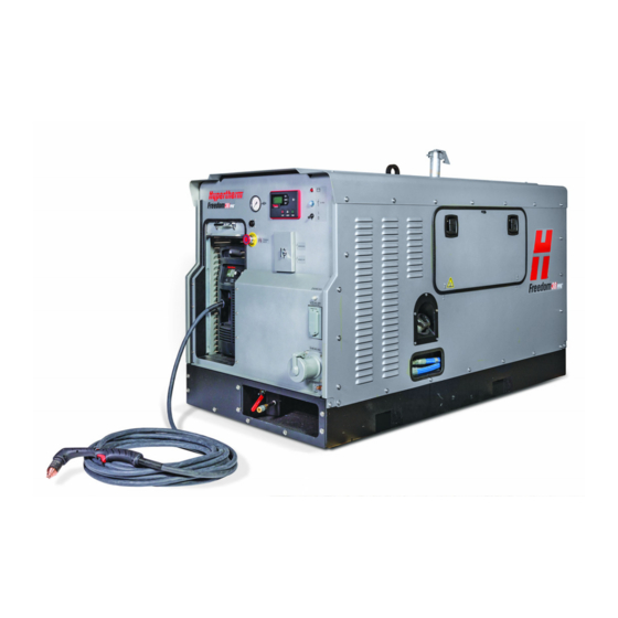
- Page 1 Freedom 38 PPA™ Large Autonomous Plasma Cutting System Service Manual 809010 | Revision 0 | English...
- Page 2 Freedom 38 PPA, Powermax, Duramax, Smart Sense, FastConnect, FineCut, and Hypertherm are trademarks of Hypertherm Inc. and may be registered in the United States and other countries. All other trademarks are the property of their respective holders. © 2017 Hypertherm Inc.
- Page 3 Freedom 38 PPA Service Manual 809010 Revision 0 English March 2017 Hypertherm Inc. Hanover, NH 03755 USA www.hypertherm.com...
- Page 4 México, D.F. C.P. 01780 (Technical Service Email) 52 55 5681 8109 Tel 52 55 5683 2127 Fax South America & Central America: Hypertherm Brasil Ltda. Soporte.Tecnico@hypertherm.com (Technical Service Email) Rua Bras Cubas, 231 – Jardim Maia Hypertherm Plasmatechnik GmbH Guarulhos, SP – Brasil...
- Page 5 한국어 / KOREAN product worden meegeleverd. De handleidingen, elke handleiding 경고! Hypertherm 장비를 사용하기 전에 제품 설명서와 안전 및 규정 beschikbaar in alle talen, zijn ook verkrijgbaar via de “Documentenbibliotheek” 준수 설명서 (80669C)에 나와 있는 안전 지침을 읽으십시오. 안전 지침을...
- Page 6 Kópia návodu, ktorá je dodávaná s produktom, môže mať elektronickú alebo tlačenú podobu. Kópie návodov, vo všetkých dostupných jazykoch, sú k dispozícii aj v sekcii z „knižnice Dokumenty“ na www.hypertherm.com.
-
Page 7: Table Of Contents
System faults ....................................22 Active faults and cleared faults ............................22 System faults triggered by predefined thresholds ......................23 Engine faults (SPN and FMI codes) ..........................25 Find system fault codes in events history ..........................27 Freedom 38 PPA Service Manual 809010... - Page 8 Replace the Dynagen system controller .......................... 92 Replace the alternator lamp ............................... 94 Replace the 12 V circuit breaker on the front panel ..................... 95 Replace the ON/OFF power switch ..........................96 Replace emergency stop contact block .......................... 98 Freedom 38 PPA Service Manual 809010...
- Page 9 Replace the air pressure gauge ............................171 Replace the unloader valve .............................. 172 Replace the muffler and orifice adapter ........................174 Replace the separation tank ............................. 175 Replace the separation tank manifold ..........................178 Replace the cooler unit ..............................181 Freedom 38 PPA Service Manual 809010...
- Page 10 Plasma torch consumables ..............................211 Hand cutting ..................................211 Mechanized cutting ................................212 Accessory parts for plasma cutting ............................213 8 Wiring Diagrams ........................215 AC wiring diagram ..................................217 12 VDC wiring diagram ................................218 Freedom 38 PPA Service Manual 809010...
-
Page 11: Warranty
Hypertherm not in strict conformity herein and as follows: if Hypertherm is notified of a defect (i) with respect with Hypertherm’s specifications and in cases of designs, processes,... -
Page 12: Liability Cap
At all times you will have and maintain insurance in such quantities and types, and with coverage sufficient and appropriate to defend and to hold Hypertherm harmless in the event of any cause of action arising from the use of the products. -
Page 13: Troubleshooting
Contact Hypertherm regarding claims for the plasma supply. Contact Hypertherm regarding system-level claims and claims for the air compressor, alternator, and digital controller. Hypertherm will connect you to the proper manufacturer, if needed. Contact Deutz regarding claims for the engine: ... - Page 14 Remove safety guards only when necessary. Replace the safety guards as soon as maintenance is complete. Close the service panels when maintenance is complete. Repair or replace the panels if they are damaged. Freedom 38 PPA Service Manual 809010...
- Page 15 Some filters can cause discomfort if they come in contact with the eyes or mouth. Wash thoroughly if your skin comes in contact with fuel or oil from the engine. NOTICE STATIC ELECTRICITY CAN DAMAGE CIRCUIT BOARDS Put on a grounded wrist strap before handling printed circuit boards. Freedom 38 PPA Service Manual 809010...
-
Page 16: System Components
16 Auxiliary air hose connector * The main circuit breaker provides power to the on-board plasma cutting system and the 480 V auxiliary outlet. The transformer circuit breaker provides power to the 120 V auxiliary outlet. Freedom 38 PPA Service Manual 809010... - Page 17 Figure 3 – Generator side 1 Fuel fill cap (diesel fuel only) 2 Oil drain hose caps for: Oil pan drain hose Heat exchanger drain hose 3 Service panel 4 Lift truck slots Freedom 38 PPA Service Manual 809010...
-
Page 18: Controls And Indicators
Use the ENTER button to display the menu system on the LCD screen and to confirm settings you changed. You can also use this button to lock the LCD screen when you view parameters. Freedom 38 PPA Service Manual 809010... - Page 19 The ON/OFF power switch should remain in the OFF (O) position when the unit is not being used. When this switch is in the ON (I) position and the unit is not running, the 12 VDC control system drains the battery over time. Freedom 38 PPA Service Manual 809010...
-
Page 20: Plasma Cutting System
Figure 5 – Plasma cutting system controls 1 Status screen 5 Power ON LED (green) 2 Fault LED (yellow) 6 Operating modes 3 Automatic/manual pressure setting mode selector 7 Operating mode switch 4 Current/gas selector 8 Adjustment knob Freedom 38 PPA Service Manual 809010... -
Page 21: Check Engine And Generator Status
2. Press the OFF button on the system controller. 3. Press the RUN button to start the engine. 4. If the control system still needs to be reset, turn the main power switch OFF (O) and then back ON (I). Freedom 38 PPA Service Manual 809010... -
Page 22: System Faults
For more information on SPN and FMI codes, see Engine faults (SPN and FMI codes) on page 25. Figure 6 – Active faults Displayed DTC message, active DTC messages Active fault with SPN and FMI codes and Fault message that displays after system shuts off OC (occurrence count) Freedom 38 PPA Service Manual 809010... -
Page 23: System Faults Triggered By Predefined Thresholds
• Check engine oil level. See page 62. • Change the oil and oil filter in the engine. See page 70. • If the problem persists, have an authorized Deutz service dealer examine the engine. Freedom 38 PPA Service Manual 809010... - Page 24 • The system may be overloaded. Remove or disconnect equipment from the 120 V and 480 V auxiliary outlets to reduce load on the system. • If the problem persists, have an authorized Deutz service dealer examine the engine. Freedom 38 PPA Service Manual 809010...
-
Page 25: Engine Faults (Spn And Fmi Codes)
Add oil as needed. See page 62. coolant sensor is faulty. • Change the oil and oil filter in the engine. See page 70. • Have an authorized Deutz service dealer examine the engine. Freedom 38 PPA Service Manual 809010... - Page 26 254 the fault persists, have an authorized Deutz service dealer examine the engine. 524287 No fault present. • No active faults are still present. Reset the control system if needed. See page 21. Freedom 38 PPA Service Manual 809010...
-
Page 27: Find System Fault Codes In Events History
Check Engine notifications include SPN and FMI codes and are specific to the engine. See Active faults and cleared faults on page 22 and Engine faults (SPN and FMI codes) on page 25. Figure 7 – Faults recorded in events history SPN code FMI code Occurrence count Freedom 38 PPA Service Manual 809010... -
Page 28: Troubleshoot Engine Issues
3. Pull down the black handle at the bottom of the shutoff valve, and hold it in place. Turn the RESET switch at the top of the valve 90° counterclockwise. Release the black handle. 4. Put the service panel back in place. Figure 8 – Air intake shutoff valve CLOSED Figure 9 – Air intake shutoff valve OPEN Freedom 38 PPA Service Manual 809010... -
Page 29: Engine Will Not Start
If yes, clear the fault condition before starting the engine. Some faults cause the engine to shut off (for example, if the engine temperature is too high or the oil pressure is too low). See System faults on page 22. If no, continue with the next step. Freedom 38 PPA Service Manual 809010... -
Page 30: Keep The Fuel System Clean
Use only clean, low-sulfur diesel fuel. Keep fuel storage containers clean and free from water and other contaminants. Use only Deutz-brand fuel filters. Replace the fuel filter regularly. See Maintenance schedules on page 53. Freedom 38 PPA Service Manual 809010... -
Page 31: Use The Hand Pump To Bleed The Fuel System
If you frequently need to bleed the fuel system in order to start the engine, this may indicate an air leak in the fuel line. Have an authorized Hypertherm Freedom 38 PPA repair facility examine the fuel supply lines, or have an authorized Deutz service dealer examine the engine. -
Page 32: Jump-Start The Battery
Reverse the battery cables. Doing so can damage the alternator. Remove the vent caps from the battery. Check the battery by producing sparks between the positive (+) and negative (-) posts. Freedom 38 PPA Service Manual 809010... - Page 33 In this case, fully charge the battery to the correct voltage with a battery charger (with the engine turned off), or install a new battery. See Replace the battery on page 89. Always dispose of old batteries in compliance with local and national regulations. Freedom 38 PPA Service Manual 809010...
- Page 34 Make sure the first cable you disconnect is the negative (-) cable connected to the engine block or chassis ground. 7. Put the service panel back in place. Figure 10 Connect positive (+) cable here Freedom 38 PPA Service Manual 809010...
-
Page 35: Common Engine And Generator Issues
• Make sure the transformer circuit breaker on the front panel is turned not display output current (amperage) for ON (I). This switch must be turned on in order to view the generator’s the generator. output current on the system controller. Freedom 38 PPA Service Manual 809010... -
Page 36: Troubleshoot Air Flow Issues (Air Compressor)
3. Inspect the torch. Are there any signs of damage that might be causing air to leak? If yes, have a Hypertherm distributor or authorized repair facility examine the torch and torch lead. If no, continue with the next step. - Page 37 If yes, allow the system to thaw. Ice can impede the compression system’s operation. If none of these steps resolve the issue, the air compressor itself may be faulty. Replace the air compressor. See page 161. Freedom 38 PPA Service Manual 809010...
-
Page 38: Troubleshoot Power-Related Issues (Generator/Alternator)
1800 RPM? Use the LCD screen on the system controller to check. See Check engine and generator status on page 21. If yes, continue with the next step. If no, have an Hypertherm Freedom 38 PPA repair facility examine the system. Freedom 38 PPA Service Manual 809010... - Page 39 7. Is the automatic voltage regulator (AVR) faulty? If yes, replace the AVR. See page 133. If no, have an Hypertherm Freedom 38 PPA repair facility examine the generator/alternator. If the problem is isolated to the 120 V auxiliary outlet the transformer may be faulty.
-
Page 40: Troubleshoot Plasma Cutting Issues
If you are unable to fix the problem by following this basic troubleshooting guide, or if you need further assistance: 1. Call your Hypertherm distributor or authorized Hypertherm repair facility. 2. Call the nearest Hypertherm office listed in the front of this manual. Common cutting issues... -
Page 41: Plasma Cutting System Fault Codes And Solutions
• 0-19 can indicate a fault that occurs 10 times without removing power. Fault code 0-99 displays. A qualified service technician must service the plasma cutting system. Contact your Hypertherm distributor or authorized repair facility. Freedom 38 PPA Service Manual 809010... - Page 42 • Leave the system ON to allow the fan in the plasma supply to cool the plasma supply. • If the internal temperature of the plasma supply approaches -30°C (-22°F), move the system to a warmer location. Freedom 38 PPA Service Manual 809010...
- Page 43 (generator/alternator) on page 38. 0-99 System hardware fault – • A qualified service technician must service service required the plasma cutting system. Contact your Hypertherm distributor or authorized repair Indicates a major fault with the facility. system. Freedom 38 PPA Service Manual 809010...
- Page 44 To display the service screen, simultaneously press the automatic/manual and current/gas mode selectors for approximately two seconds. Automatic/manual mode Current/gas selector mode selector Freedom 38 PPA Service Manual 809010...
- Page 45 DSP/control board software versions (callouts 1 – 6) Fault log of recent fault codes recorded by the system (0-00-0) and the last three digits of the arc hour count when the fault occurred (000). Freedom 38 PPA Service Manual 809010...
- Page 46 3. Use the adjustment knob to set the gas test field from 0 to 1. If gas does not flow, call your Hypertherm distributor or authorized repair facility, or call the nearest Hypertherm office listed in the front of this manual.
-
Page 47: Find Serial Numbers
The serial number for the system is located on the system’s data plate. The data plate is located in 2 places: On the system’s front panel On the lift-eye frame on the generator side of the system. Freedom 38 PPA Service Manual 809010... -
Page 48: Serial Number For The Generator
Serial number for the engine The serial number for the engine is located on top of the engine near the rear panel. Remove the top cover from the system to see the serial number. Freedom 38 PPA Service Manual 809010... -
Page 49: Serial Number For The Alternator
On the inner side of the alternator behind the plasma cutting system. Move the plasma cutting system to see this serial number. You may also need to remove the cover on the plasma side of the system. Freedom 38 PPA Service Manual 809010... -
Page 50: Serial Number And Version Numbers For The System Controller
3. Use the arrow buttons to navigate to the Device Info command. 4. Press the ENTER button to display the system controller’s hardware version (HV), software version (SV), and serial number (SN). Freedom 38 PPA Service Manual 809010... -
Page 51: Serial Number For The Air Compressor
Remove the rear panel to see the serial number. Serial number for the plasma cutting system The serial number for the plasma cutting system is located on the data plate on the system’s rear panel, next to its power cord. Freedom 38 PPA Service Manual 809010... - Page 52 1 – Troubleshooting Freedom 38 PPA Service Manual 809010...
-
Page 53: Routine Maintenance
Some filters can cause discomfort if they come in contact with the eyes or mouth. Wash thoroughly if your skin comes in contact with fuel or oil from the engine. NOTICE Do not use a pressure washer to clean the outside of the system. Freedom 38 PPA Service Manual 809010... - Page 54 Close the service panels when maintenance is complete. Repair or replace the panels if they are damaged. NOTICE STATIC ELECTRICITY CAN DAMAGE CIRCUIT BOARDS Put on a grounded wrist strap before handling printed circuit boards. Freedom 38 PPA Service Manual 809010...
- Page 55 Check the oil level in the air compressor. See page 63. Every month System component Recommended maintenance Test the GFCI protection on the 120 V auxiliary outlet. See page 66. Engine/generator Replace the air drying filter. See page 67. Air compressor Freedom 38 PPA Service Manual 809010...
- Page 56 If applicable, inspect the screws on the machine torch that connect the torch body to the mounting sleeve. Tighten the screws, if needed. * Hypertherm strongly recommends that only authorized service technicians do this maintenance. Freedom 38 PPA Service Manual 809010...
- Page 57 See page 78. Air compressor In very dusty or dirty environments, change the oil more than once per year. * Hypertherm strongly recommends that only authorized service technicians do this maintenance. Freedom 38 PPA Service Manual 809010...
- Page 58 Change the oil separation filter. * See page 81. Air compressor Clean the finned surface of the air/oil cooler. * * Hypertherm strongly recommends that only authorized service technicians do this maintenance. Every 6,000 operating hours System component Recommended maintenance ...
-
Page 59: Routine Maintenance Procedures
See Every 3 months (or 500 operating hours) on page 69. See Every 6 months on page 73. See Every year on page 78. See Every 4,000 operating hours on page 81. Freedom 38 PPA Service Manual 809010... -
Page 60: Every Use
The surface for damage, wear, or a lack If the O-ring is dry, lubricate it and the of lubrication. threads with a thin layer of silicone lubricant. If the O-ring is worn or damaged, replace it. Torch O-ring Freedom 38 PPA Service Manual 809010... - Page 61 4. When the air draining from the tank is clear, close the valve by rotating the lever towards you until it is parallel with the bottom of the system. Figure 11 Rotate lever down to drain air tank Freedom 38 PPA Service Manual 809010...
-
Page 62: Every Day
Do not exceed the maximum fill level. For details on how to add oil to the engine, see Change the oil and oil filter in the engine on page 70. Figure 12 – Engine oil dipstick Freedom 38 PPA Service Manual 809010... -
Page 63: Every Week
5 mm (1/4 inch). Use the ring at the end of the valve. This discharges internal pressure from the air compressor. 4. Drain the air tank to release pressure. See page 61. Freedom 38 PPA Service Manual 809010... - Page 64 Do not exceed the maximum fill level. See Figure 13 on page 63. 7. Screw the fill cap back onto the top of the air/oil separation tank. 8. Put the system’s panels back in place. See Install the cover on page 88. Figure 14 Freedom 38 PPA Service Manual 809010...
- Page 65 The condensate exits through the baseboard on the plasma side of the system by the rear panel. 5. Dispose of the condensate in compliance with local and national regulations. 6. Put the service panel back in place. Freedom 38 PPA Service Manual 809010...
-
Page 66: Every Month
4. Press the Test button on the GFCI outlet. 5. Did the GFCI Reset button extrude? If yes, press the Reset button. GFCI protection is working properly. If no, have an authorized service technician replace the GFCI outlet. Freedom 38 PPA Service Manual 809010... - Page 67 7. Lightly apply clean oil to the seal on the new air drying filter. 8. Screw the air drying filter into place. Tighten by hand plus a 3/4 turn. Freedom 38 PPA Service Manual 809010...
- Page 68 2 – Routine Maintenance 9. Put the service panel back in place. Figure 15 – Air drying filter Freedom 38 PPA Service Manual 809010...
-
Page 69: Every 3 Months (Or 500 Operating Hours)
1. Turn OFF the system. Make sure the power switch on the front panel is in the OFF (O) position. 2. Remove the service panel on the plasma side of the system. Freedom 38 PPA Service Manual 809010... - Page 70 When changing the oil in the engine, always use the same type of oil. Do not mix different types of oil. Use only Deutz-brand oil filters. This engine is cooled by the lubricating oil, so the oil must be drained from both the oil pan and the heat exchanger. Freedom 38 PPA Service Manual 809010...
- Page 71 14. Pull the other drain hose out from the system, and move the container underneath the end of the hose. Repeat step 12 and step 13 to drain the oil from the second hose. 15. Dispose of the old oil in compliance with local and national regulations. Freedom 38 PPA Service Manual 809010...
- Page 72 23. Put the top cover and the generator-side panel back in place, if you removed them. See Install the cover on page 88. 24. Put the service panel back in place. Figure 17 Oil filter Drain hoses for Oil fill cap oil pan and heat exchanger Oil dipstick Freedom 38 PPA Service Manual 809010...
-
Page 73: Every 6 Months
This circulates fuel through the new filter. See Figure 18. You may need to push in the hand pump as many as 20 times. 10. Reconnect the negative (-) ground cable to the battery. 11. Put the service panel back in place. Freedom 38 PPA Service Manual 809010... - Page 74 2 – Routine Maintenance Figure 18 – Engine fuel filter Hand pump Freedom 38 PPA Service Manual 809010...
- Page 75 11. Reconnect the negative (-) ground cable to the battery. 12. Put the service panel back in place. 13. Turn ON the system. Make sure there are no fuel leaks. Freedom 38 PPA Service Manual 809010...
- Page 76 3. Remove the service panel on the generator side of the system. 4. Pull back the 3 clips, and remove the cover from the air cleaner. See Figure 19. Figure 19 Clips Cover of air cleaner Freedom 38 PPA Service Manual 809010...
- Page 77 13. Empty the air cleaner’s dust discharge valve by pinching the discharge slot. After the valve is empty, clean the discharge slot. 14. Reconnect the negative (-) ground cable to the battery. 15. Put the service panel back in place. Freedom 38 PPA Service Manual 809010...
-
Page 78: Every Year
The viscosity grade must correspond to the ambient temperature and ISO 3448: Ambient temperature Viscosity grade Viscosity index Consistently above 25°C (77°F) ISO VG 68 Minimum 95 Between 25°C (77°F) and 0°C (32°F) ISO VG 46 Minimum 95 Freedom 38 PPA Service Manual 809010... - Page 79 Condensate may discharge from the tank before the oil starts to drain. c. After the oil drains from the tank, close the valve. Dispose of the old oil in compliance with local and national regulations. Freedom 38 PPA Service Manual 809010...
- Page 80 Turn ON the system, and allow it to run until the cooler unit is hot. Shut down the system and check the oil level. Figure 20 – Air compressor’s oil filter and air/oil separation tank Freedom 38 PPA Service Manual 809010...
-
Page 81: Every 4,000 Operating Hours
See Figure 21. Dispose of old oil and filters in compliance with local and national regulations. 6. Lightly apply clean oil to the seal on the new oil separation filter. 7. Screw the oil separation filter into place. Tighten by hand. Freedom 38 PPA Service Manual 809010... - Page 82 2 – Routine Maintenance 8. Put the service panel back in place. Figure 21 – Air compressor’s oil separation filter Freedom 38 PPA Service Manual 809010...
-
Page 83: System-Level Components
Handle all engine filters, fuel, and lubricating oils with care. Fuel and lubricating oils can irritate skin. Some filters can cause discomfort if they come in contact with the eyes or mouth. Wash thoroughly if your skin comes in contact with fuel or oil from the engine. Freedom 38 PPA Service Manual 809010... - Page 84 Close the service panels when maintenance is complete. Repair or replace the panels if they are damaged. NOTICE STATIC ELECTRICITY CAN DAMAGE CIRCUIT BOARDS Put on a grounded wrist strap before handling printed circuit boards. Freedom 38 PPA Service Manual 809010...
- Page 85 Replace the service panel compression latch on page 104 Replace the 120 V auxiliary outlet on page 105 Replace 120 V auxiliary outlet circuit breaker on page 106 Replace the front panel on page 107 Freedom 38 PPA Service Manual 809010...
-
Page 86: Remove And Install The System's Cover
You must remove both side panels before you can remove the rear panel. Remove only the screws and washers that attach the side panels. Leave the front panel and rear panel screws that secure the bottoms to the chassis until removing those assemblies. Figure 22 Freedom 38 PPA Service Manual 809010... - Page 87 Set aside with all the screws and washers. Figure 23 NOTICE Do not remove the front panel unless absolutely necessary. All of the front panel controls must be disconnected before the front panel can be removed. See page 107. Freedom 38 PPA Service Manual 809010...
- Page 88 NOTICE The cap must be put back in place on the exhaust pipe. If it is left off, water, debris, and other contaminants can enter the pipe and cause severe damage to the engine. Freedom 38 PPA Service Manual 809010...
-
Page 89: Replace The Battery
Always dispose of old batteries in compliance with local and national regulations. Examine the chassis ground strap connection regularly. Without a solid ground strap connection, electrical discharge can damage the engine and electrical system. Freedom 38 PPA Service Manual 809010... - Page 90 Remove the battery The Freedom 38 PPA requires a 12 VDC battery with a capacity of 750 cold cranking amperes (CCA). The system ships with a Battery Charging Indicator (BCI) group 34/78 12 V battery. Replace it with a battery of comparable specifications and size.
- Page 91 Cover the terminal with the black sleeve from the cable, as shown in Figure 25. 6. Make sure both battery cable connections are tightened securely before starting the system. 7. Put the service panel back in place. Figure 25 Freedom 38 PPA Service Manual 809010...
-
Page 92: Replace The Dynagen System Controller
6. Put the system’s top cover back in place. See Install the cover on page 88. 7. Set the power switch on the front panel to the ON (I) position. Examine the LCD screen to make sure the new system controller is working properly. Freedom 38 PPA Service Manual 809010... - Page 93 3 – System-Level Components Figure 26 Freedom 38 PPA Service Manual 809010...
-
Page 94: Replace The Alternator Lamp
5. Put the system’s top cover back in place. See Install the cover on page 88. 6. Reconnect the negative (-) ground cable to the battery. Figure 27 Freedom 38 PPA Service Manual 809010... -
Page 95: Replace The 12 V Circuit Breaker On The Front Panel
12 V circuit breaker Figure 28 5. Gently pull on the circuit breaker from outside the front panel. At the same time, slowly push the back of the circuit breaker through the lock washer Freedom 38 PPA Service Manual 809010... -
Page 96: Replace The On/Off Power Switch
5. Carefully remove the rubber cover from the front of the power switch. To do this, hold the back of the power switch in place. At the same time, unscrew the base of the rubber cover until you can remove it from the power switch. Set the rubber cover aside. Freedom 38 PPA Service Manual 809010... - Page 97 8. Make sure the power switch is in the OFF (O) position (pointing down). 9. Put the system’s top cover back in place. See Install the cover on page 88. 10. Reconnect the negative (-) ground cable to the battery. Freedom 38 PPA Service Manual 809010...
-
Page 98: Replace Emergency Stop Contact Block
2. Secure the contact block to the emergency stop plate by tightening the 2 screws 3. Put the system’s top cover back in place. See Install the cover on page 88. 4. Reconnect the negative (-) ground cable to the battery. Freedom 38 PPA Service Manual 809010... -
Page 99: Replace Emergency Stop Button
Kit: Emergency Stop button Remove the emergency stop button 1. Loosen and remove the emergency stop button by turning counterclockwise. Figure 31 Install the emergency stop button 1. Tighten the new emergency stop button by turning clockwise. Freedom 38 PPA Service Manual 809010... -
Page 100: Replace Front Panel Circuit Breaker
5. Remove the circuit breaker that needs replacement from the bracket. (The top breaker is 60 A. The bottom breaker is 10 A.) Unscrew the wires from the breaker by loosening the terminal screws and pulling the wires out. See Figure 32. Figure 32 Freedom 38 PPA Service Manual 809010... - Page 101 3. Reinstall the circuit breaker bracket to the AC connection cabinet. 4. Reinstall the cover to the top of the AC connection cabinet. 5. Reinstall the front panel. See Reattach the front panel on page 125. Freedom 38 PPA Service Manual 809010...
-
Page 102: Replace The 480 V Auxiliary Outlet
Mark the order of the wire colors and location to the receptacle. Check that the wires are stripped clean and there are no stray wire strands Ground/neutral White Black Orange Freedom 38 PPA Service Manual 809010... - Page 103 5. Set the receptacle and gasket into the front panel with the hinge facing up. Secure using the 4 screws and torque to 34.56 kg∙cm (30 in∙lb minimum) / 46.08 kg∙cm (40 in∙lb maximum). Freedom 38 PPA Service Manual 809010...
-
Page 104: Replace The Service Panel Compression Latch
When you put the service panel in place, you may need to adjust the cam position by positioning the jam nuts and lock washers. With the cam properly positioned, tighten the nuts to secure it in place. Figure 35 Freedom 38 PPA Service Manual 809010... -
Page 105: Replace The 120 V Auxiliary Outlet
3. Put the cover and gasket back in place and secure with 2 screws. 4. Reconnect the negative (-) ground cable to the battery. 5. Test the GFCI circuit. See Test the GFCI outlet on page 66. Freedom 38 PPA Service Manual 809010... -
Page 106: Replace 120 V Auxiliary Outlet Circuit Breaker
Secure by tightening the water resistant cover over the button. 3. Put the system’s top cover and engine-side panel back in place. See Install the cover on page 88. 4. Reconnect the negative (-) ground cable to the battery. Freedom 38 PPA Service Manual 809010... -
Page 107: Replace The Front Panel
Kit: Front panel (hardware not included) 428506 Kit: Labels for front panel controls 428507 Kit: Freedom 38 PPA decal for front and rear panels 428508 Kit: Yellow warning sticker for Emergency Stop button Remove the front panel 1. Turn OFF the system. Make sure the power switch on the front panel is in the OFF (O) position. - Page 108 120 V outlet 120 V outlet cover 120 V circuit breaker Front panel breaker cover ON/OFF power switch Dynagen controller 12 V circuit breaker Air pressure gauge Alternator lamp Edge trim CPC connector Front panel Freedom 38 PPA Service Manual 809010...
- Page 109 Alternator lamp. See Install the alternator lamp on page 94. ON/OFF power switch. See Install the ON/OFF power switch on page 97. 120 V circuit breaker. See Install the 120 V auxiliary outlet circuit breaker on page 106. Freedom 38 PPA Service Manual 809010...
- Page 110 Figure 41 428507 428508 428506 12. Put the system’s top cover and side panels back in place. See Install the cover on page 88. 13. Reconnect the negative (-) ground cable to the battery. Freedom 38 PPA Service Manual 809010...
-
Page 111: Plasma Components
Handle all engine filters, fuel, and lubricating oils with care. Fuel and lubricating oils can irritate skin. Some filters can cause discomfort if they come in contact with the eyes or mouth. Wash thoroughly if your skin comes in contact with fuel or oil from the engine. Freedom 38 PPA Service Manual 809010... - Page 112 Close the service panels when maintenance is complete. Repair or replace the panels if they are damaged. NOTICE STATIC ELECTRICITY CAN DAMAGE CIRCUIT BOARDS Put on a grounded wrist strap before handling printed circuit boards. Freedom 38 PPA Service Manual 809010...
- Page 113 Replace the air filter element and air filter bowl in the plasma supply on page 114. Detach the plasma supply power cord on page 115. Unfasten the plasma supply on page 118. Freedom 38 PPA Service Manual 809010...
-
Page 114: Replace The Air Filter Element And Air Filter Bowl In The Plasma Supply
1. Refer to the Maintenance and Repair chapter in the Powermax125 Operator Manual to install a new air filter element and air filter bowl. 2. Reconnect the compressed air hose to the back of the plasma supply. 3. Put the service panel back in place. Freedom 38 PPA Service Manual 809010... -
Page 115: Detach The Plasma Supply Power Cord
5. Remove the connections from the rear of the plasma supply. See Detach the plasma supply on page 118. 6. Remove the cover from the top of the AC connection cabinet that is located on top of the generator. Figure 42 Freedom 38 PPA Service Manual 809010... - Page 116 These are located outside the AC connection cabinet on the plasma side. Figure 43 wires. See Figure 44. 8. Disconnect the power cord’s black , white , and red Figure 44 Freedom 38 PPA Service Manual 809010...
- Page 117 9. Reconnect the plasma supply. See Reattach the plasma supply on page 120. 10. Put the system’s top cover and side panels back in place. See Install the cover on page 88. 11. Reconnect the negative (-) ground cable to the battery. Freedom 38 PPA Service Manual 809010...
-
Page 118: Unfasten The Plasma Supply
OFF (O). 5. Disconnect the compressed air hose 6. Disconnect the machine interface (CPC) connector Figure 45 7. Remove the 2 screws that secure the rear bracket of the plasma supply. Freedom 38 PPA Service Manual 809010... - Page 119 Figure 46 9. Grip the front and rear handles at the top of the plasma supply. Slide the plasma supply forward to free it from the front bracket Freedom 38 PPA Service Manual 809010...
- Page 120 5. Set the power switch on the back of the plasma supply to ON (I). 6. Reconnect the negative (-) ground cable to the battery. 7. Put the system’s top cover and plasma-side panel back in place. See Install the cover on page 88. Freedom 38 PPA Service Manual 809010...
-
Page 121: Generator And Engine Components
Handle all engine filters, fuel, and lubricating oils with care. Fuel and lubricating oils can irritate skin. Some filters can cause discomfort if they come in contact with the eyes or mouth. Wash thoroughly if your skin comes in contact with fuel or oil from the engine. Freedom 38 PPA Service Manual 809010... - Page 122 Close the service panels when maintenance is complete. Repair or replace the panels if they are damaged. NOTICE STATIC ELECTRICITY CAN DAMAGE CIRCUIT BOARDS Put on a grounded wrist strap before handling printed circuit boards. Freedom 38 PPA Service Manual 809010...
- Page 123 Replace the relays on page 150. Replace the fuel shutoff relay on page 151. Replace the cooling unit fan relay on page 152. Replace the generator rectifiers on page 153. Freedom 38 PPA Service Manual 809010...
-
Page 124: Unfasten The Front Panel
3. Remove the top cover and both side panels from the system. See Remove the cover on page 86. 4. Remove the 4 screws and nuts that secure the CPC connector to the front panel. 5. Remove the 2 bottom screws securing the front panel to the base. Figure 48 Freedom 38 PPA Service Manual 809010... - Page 125 3. Reconnect the CPC connector to the front panel using the 4 screws and nuts. 4. Put the system’s top cover and panels back in place. See Install the cover on page 88. 5. Reconnect the negative (-) ground cable to the battery. Freedom 38 PPA Service Manual 809010...
-
Page 126: Replace The Transformer
4. Remove the plasma supply. See Detach the plasma supply on page 118. 5. Remove the 6 screws and washers that secure the plasma supply bracket. Set aside the bracket and hardware. Figure 50 Freedom 38 PPA Service Manual 809010... - Page 127 7. Remove the condensate valve and auxiliary air bracket . Disconnect the hoses on the condensate valve if necessary. 8. Remove the transformer screws Figure 51 9. Have another person help to carefully lift the transformer out of the system. Freedom 38 PPA Service Manual 809010...
- Page 128 The 120 V cable is the one that connects to the 120 V outlet on the front panel. The 480 V cable comes from the front panel 10 A circuit breaker in the AC connection cabinet. Freedom 38 PPA Service Manual 809010...
- Page 129 10. Reinstall the plasma supply. See page 120. 11. Reattach the front panel. See page 125. 12. Put the system’s top cover and panels back in place. See Install the cover on page 88. Freedom 38 PPA Service Manual 809010...
-
Page 130: Replace The Emergency Air Intake Shut-Off Valve
Work the pipe loose from the elbow. 5. Loosen the hose clamps on both sides of the air intake shut-off valve . Unplug the wire harness connection Figure 54 Freedom 38 PPA Service Manual 809010... - Page 131 3. Put the assembly back into place between the air intake pipe and the air intake opening. 4. Tighten the 4 hose clamps. Reconnect the plug from the wiring harness. 5. Place the air intake pipe back into the rubber elbow. Tighten the hose clamp to secure it. Freedom 38 PPA Service Manual 809010...
- Page 132 7. Make sure the emergency air intake shut-off valve is set to the OPEN position 8. Put the system’s top cover and plasma-side panel back in place. See Install the cover on page 88. 9. Reconnect the negative (-) ground cable to the battery. Freedom 38 PPA Service Manual 809010...
-
Page 133: Replace The Automatic Voltage Regulator (Avr)
4. Remove the cover panel from the AVR. See Figure 57. 5. Remove the 4 screws that secure the AVR. 6. Disconnect the 4 wire connections from the top of the AVR. 7. Remove the AVR from the alternator. Figure 57 Freedom 38 PPA Service Manual 809010... - Page 134 Figure 58 (white) (white) (red) (white) 3. Install the 4 screws to secure the AVR to the alternator. 4. Reconnect the negative (-) ground cable to the battery. 5. Turn ON (I) the power switch. Freedom 38 PPA Service Manual 809010...
- Page 135 Turn counterclockwise to decrease the drooping effect. Use the bottom adjustment to set the stabilization effect: Turn clockwise to increase the stabilization effect. Turn counterclockwise to decrease the stabilization effect. Figure 59 Freedom 38 PPA Service Manual 809010...
-
Page 136: Replace The Fuel-Level Sensor
5. Clean the area around the fuel-sensor of dirt and debris so that nothing can fall into the opening when removing the sensor. 6. Remove the 5 screws to disconnect the fuel-level sensor from the fuel tank. Freedom 38 PPA Service Manual 809010... - Page 137 Secure with cable ties. Reconnect the ring terminals from the wiring harness and the new fuel sensor to the grounding bracket on the fuel tank. Figure 61 Freedom 38 PPA Service Manual 809010...
-
Page 138: Replace The Ac Sensor Wiring Harnesses
They are not part of the wire harness. 6. Remove the 6 wire connections (431, 432, 433, 420 X 3) from the current sensors. Remove the wires from the neutral stud (420/220). Freedom 38 PPA Service Manual 809010... - Page 139 5. Tighten the strain relief in the AC connection cabinet by tightening the outer nut. Secure the wiring harness with cable ties as necessary. 6. Reattach the front panel. See page 125. 7. Replace the cover and panels. See Install the cover on page 88. Freedom 38 PPA Service Manual 809010...
-
Page 140: Replace The Control System Wiring Harness
Emergency stop contact block. See Remove the emergency stop contact block on page 98. Fuel shutoff relay. See Remove the fuel shutoff relay on page 151. 6. Remove the diagnose plug. Figure 63 Freedom 38 PPA Service Manual 809010... - Page 141 5. Secure the harness assembly with cable ties. 6. Put the system’s top cover back in place. See Install the cover on page 88. 7. Reconnect the negative (-) ground cable to the battery. Freedom 38 PPA Service Manual 809010...
-
Page 142: Replace The Generator Wiring Harness
4. Start from the engine side. Cut the cable tie and unplug the top large gray connector from the generator. Figure 65 5. Unplug the connection to the engine wire harness located near the gas port. Cut the cable ties to free the connectors. Figure 66 Freedom 38 PPA Service Manual 809010... - Page 143 6. Located on the generator below the air filter housing is the interconnect between the generator and control harnesses. Disconnect the 2 gray connectors. Figure 67 7. Move to the plasma side. Remove the nut and washer to disconnect the ground terminal wires from the engine. Figure 68 Freedom 38 PPA Service Manual 809010...
- Page 144 Figure 69 – Starter motor connections 9. Disconnect the red wire from the battery positive (+) terminal connection. Figure 70 10. Disconnect the fuel-level sensor. See Remove the fuel-level sensor on page 136. Freedom 38 PPA Service Manual 809010...
- Page 145 14. Unplug the connector from the emergency air shutoff relay if installed. (This is an option.) See Figure 54 on page 130. 15. Disconnect the yellow/brown wire from the air compressor’s temperature switch. See Remove the temperature switch, tee fitting, elbow fitting, and adapter on page 167. Freedom 38 PPA Service Manual 809010...
- Page 146 Remove the screw and remove the relay socket from the fan bracket assembly. 19. Remove the red protective cover on the circuit breaker and disconnect the 2 wires. Freedom 38 PPA Service Manual 809010...
- Page 147 16. Secure the generator wiring harness with cable ties as necessary. 17. Put the system’s top cover, side panels, and rear panel back in place. See Install the cover on page 88. 18. Reconnect the negative (-) ground cable to the battery. Freedom 38 PPA Service Manual 809010...
-
Page 148: Replace The Engine Wiring Harness
4. Cut the cable tie and unplug the lower large gray connector from the generator. Figure 75 5. Unplug the connection to the engine wire harness located near the gas port. Cut the cable ties to free the connectors. See Figure 66 on page 142. Freedom 38 PPA Service Manual 809010... - Page 149 3. Connect the 4 remaining plugs into the appropriate connections on the engine. See Figure 76. 4. Put the system’s top cover and engine-side panel back in place. See Install the cover on page 88. 5. Reconnect the negative (-) ground cable to the battery. Freedom 38 PPA Service Manual 809010...
-
Page 150: Replace The Relays
Install the engine mounted relay 1. Place the new relay in the appropriate slot in the housing. 2. Reconnect the negative (-) ground cable to the battery. 3. Put the plasma side service panel back in place. Freedom 38 PPA Service Manual 809010... -
Page 151: Replace The Fuel Shutoff Relay
2. Secure the relay to the rear of the front panel using the washer, toothed washer, and screw. 3. Put the system’s top cover back in place. See Install the cover on page 88. 4. Reconnect the negative (-) ground cable to the battery. Freedom 38 PPA Service Manual 809010... -
Page 152: Replace The Cooling Unit Fan Relay
1. Plug the new relay into the relay housing. 2. Put the system’s top cover back in place. See Install the cover on page 88. 3. Reconnect the negative (-) ground cable to the battery. Freedom 38 PPA Service Manual 809010... -
Page 153: Replace The Generator Rectifiers
1. Turn OFF the system. Make sure the power switch on the front panel is in the OFF (O) position. 2. Remove the front panel. See Unfasten the front panel on page 124. 3. Remove the plastic end cover on the generator. Figure 80 Freedom 38 PPA Service Manual 809010... - Page 154 2. Repeat for each diode, then replace the varistor. The varistor is secured with 2 screws. 3. Reconnect the generator’s plastic cover and secure with screws. 4. Replace the front panel. See Reattach the front panel on page 125. Freedom 38 PPA Service Manual 809010...
-
Page 155: Air Compression Components
Handle all engine filters, fuel, and lubricating oils with care. Fuel and lubricating oils can irritate skin. Some filters can cause discomfort if they come in contact with the eyes or mouth. Wash thoroughly if your skin comes in contact with fuel or oil from the engine. Freedom 38 PPA Service Manual 809010... - Page 156 Close the service panels when maintenance is complete. Repair or replace the panels if they are damaged. NOTICE STATIC ELECTRICITY CAN DAMAGE CIRCUIT BOARDS Put on a grounded wrist strap before handling printed circuit boards. Freedom 38 PPA Service Manual 809010...
- Page 157 Replace the compressor inlet valve on page 166 Replace the air compressor temperature switch, tee fitting, elbow fitting, and adapter on page 167 Replace the air compressor check valve and scavenge line orifice on page 169 Freedom 38 PPA Service Manual 809010...
- Page 158 Pressure in the separation tank manifold should be released by the valve on the separation tank manifold prior to servicing any air compression lines or hoses. Freedom 38 PPA Service Manual 809010...
- Page 159 5 Oil separation filter 14 Oil return line 6 Temperature switch 15 Compressed air and oil out 7 Compressor 16 Air drying filter 8 Separation tank 17 Auxiliary air line 9 Air cooler 18 Pressure gauge Freedom 38 PPA Service Manual 809010...
-
Page 160: Replace The Air Compressor Belt
For a used belt set the tension to 196 – 209 N (44 – 47 pound-force). When the tension pulley is set correctly tighten the outer nut onto the first nut to lock it in place. Freedom 38 PPA Service Manual 809010... -
Page 161: Replace The Air Compressor And Drive Pulley
6. Remove the air compressor belt. See Remove the air compressor belt on page 160. 7. Place a tray or container next to the compressor to catch any oil that drips from the hoses. Freedom 38 PPA Service Manual 809010... - Page 162 Figure 85 Loosen (LH) 12. Remove the compressor inlet valve , oil line elbow fitting , and tee elbow fitting 13. Remove 3 screws and washers that secure the compressor to the bracket. Freedom 38 PPA Service Manual 809010...
- Page 163 Use an impact tool to obtain the correct torque setting for the nut. NOTICE Proper torque of the nut is critical. Too tight and the shaft may break. Too loose and the pulley may slip. Freedom 38 PPA Service Manual 809010...
- Page 164 12. Turn OFF the system, and check the oil level in the air compressor after the oil has had time to settle. See page 63. 13. Periodically check the air compressor to make sure there are no oil leaks. Freedom 38 PPA Service Manual 809010...
-
Page 165: Replace The Compressor Tension Pulley
Figure 88 – Air compressor tension pulley assembly 2. Perform the following procedure starting at the installation of the compressor assembly. Install the air compressor on page 163. Freedom 38 PPA Service Manual 809010... -
Page 166: Replace The Compressor Inlet Valve
5. Connect the air intake hose to the control valve. Tighten the hose clamp to secure the hose. 6. Reinstall the black base board under the rear panel. 7. Reconnect the negative (-) ground cable to the battery. Freedom 38 PPA Service Manual 809010... -
Page 167: Replace The Air Compressor Temperature Switch, Tee Fitting, Elbow Fitting, And Adapter
7. Place a small container or pan under the front of the air compressor to catch any oil that spills. 8. Use a large adjustable wrench to remove the temperature switch from the fitting on the air compressor. Remove the washer. Freedom 38 PPA Service Manual 809010... - Page 168 , elbow fitting , or straight adapter as needed. Disconnect the 45° fitting when replacing the tee fitting. 11. Dispose of any oil that spilled in compliance with local and national regulations. Figure 91 Freedom 38 PPA Service Manual 809010...
-
Page 169: Replace The Air Compressor Check Valve And Scavenge Line Orifice
Place in a container to catch oil drippings. See Figure 92 on page 170. 7. Remove the adapter from the scavenge line orifice 8. Unscrew the check valve from the compressor inlet valve . Dispose of oil according to local and national regulations. Freedom 38 PPA Service Manual 809010... - Page 170 9. Press the OFF (O) button on the system controller to turn OFF the system. Make sure the power switch on the front panel is in the OFF (O) position. 10. Check for leaks and check the oil level. See Check the oil level in the air compressor on page 63. Freedom 38 PPA Service Manual 809010...
-
Page 171: Replace The Air Pressure Gauge
When loose the bracket can be removed with a twist. 6. Remove the air pressure gauge from the front panel. 7. Disconnect the 90° fitting from the back of the air pressure gauge. Freedom 38 PPA Service Manual 809010... -
Page 172: Replace The Unloader Valve
. See Figure 94 on page 173. 6. Use 2 wrenches remove the output hose from the valve’s elbow fitting . Use 2 wrenches to remove the valve assembly from the separation tank manifold Freedom 38 PPA Service Manual 809010... - Page 173 1. Use 2 wrenches to connect the valve assembly to the separation tank manifold. 2. Use 2 wrenches to connect the output hose to the valve’s elbow fitting. 3. Reconnect the battery’s negative (-) ground cable. 4. Replace the plasma-side service panel. Freedom 38 PPA Service Manual 809010...
-
Page 174: Replace The Muffler And Orifice Adapter
7. To remove the muffler from the orifice adapter use 2 wrenches. Place one wrench on the orifice adapter to hold it steady. Place the other wrench on the muffler , and turn the muffler wrench to remove it. Freedom 38 PPA Service Manual 809010... -
Page 175: Replace The Separation Tank
7. Drain the oil from the separation tank. See page 79. 8. Remove the screws and washers that secure the manifold. Remove the manifold from the separation tank. Retain the O-rings for installation on the new tank. Freedom 38 PPA Service Manual 809010... - Page 176 , valve and elbows , oil cap , and input elbow connector from the old tank. The valve and elbows need to be disassembled to remove them from the bottom of the tank. Figure 97 Freedom 38 PPA Service Manual 809010...
- Page 177 11. Check for leaks and check the oil level. See Check the oil level in the air compressor on page 63. 12. Replace the top cover and plasma-side panel on the system. See Install the cover on page 88. Freedom 38 PPA Service Manual 809010...
-
Page 178: Replace The Separation Tank Manifold
Air/oil line from the compressor Air cooler hose 2 oil cooler hoses Oil mist line to the compressor Oil return line the compressor Figure 98 Freedom 38 PPA Service Manual 809010... - Page 179 5. Remove the remaining fittings from the old manifold. Install each fitting to the appropriate location on the new manifold. Use part number 330116 thread sealant. Apply a thread seal bead on 2–3 threads of each fitting. Do not over-apply to avoid air line contamination. Figure 99 – Separation tank manifold fittings Freedom 38 PPA Service Manual 809010...
- Page 180 14. Check for leaks and check the oil level. See Check the oil level in the air compressor on page 63. 15. Replace the top cover and plasma-side panel on the system. See Install the cover on page 88. Freedom 38 PPA Service Manual 809010...
-
Page 181: Replace The Cooler Unit
(5/8 inch by 3/4 inch) foam rubber. 8. Remove the cooling unit being replaced by cutting it out of the mounting bracket and free from the other unit. Leave the foam on the good unit. Freedom 38 PPA Service Manual 809010... - Page 182 Set the power switch on the front panel to ON (|) and press the RUN button on the system controller. 10. After the unit starts up allow it to run for approximately 5 minutes. Freedom 38 PPA Service Manual 809010...
-
Page 183: Replace The Compressor Cooling Fan
3. Remove the top cover, side panels, and rear panel from the system. See Remove the cover on page 86. 4. Unplug the 2 wiring harness connectors from the fan connector. 5. Remove the 4 screws that secure the fan to the bracket. Figure 102 – Fan Assembly Freedom 38 PPA Service Manual 809010... - Page 184 7. Press the OFF (O) button on the system controller to turn OFF the system. Make sure the power switch on the front panel is in the OFF (O) position. Freedom 38 PPA Service Manual 809010...
-
Page 185: Replace The Pressure Relief Valve On The Separation Tank
1. Install the new pressure relief valve. Use part number 330116 thread sealant on the relief valve. Apply a thread seal bead on 2–3 threads. Do not over-apply to avoid air line contamination. 2. Reconnect the battery’s negative (-) ground cable. 3. Replace the plasma-side service panel. Freedom 38 PPA Service Manual 809010... -
Page 186: Replace The Oil Level Gauge
Ensure that the hose clamp’s tightening screw location will not interfere with the side panel when installed. 4. Reconnect the battery’s negative (-) ground cable. 5. Replace the top cover and plasma-side panel on the system. See Install the cover on page 88. Freedom 38 PPA Service Manual 809010... -
Page 187: Replace The Air Drying Filter Assembly
. See Remove the pressure relief valve on the air drying filter assembly on page 190. 7. Disconnect the unloader valve hose 8. Disconnect the air tank hose 9. Remove the adapter from the air drying filter assembly where the air tank hose was attached Figure 105 Freedom 38 PPA Service Manual 809010... - Page 188 12. Remove the screws, nuts, and washers that secure the air drying filter assembly to the chassis. Remove the air drying filter assembly from the unit. Cut any cable ties necessary to free the part. Figure 107 Freedom 38 PPA Service Manual 809010...
- Page 189 10. Redress any hoses and replace any cable ties cut from the removal process. 11. Reconnect the battery’s negative (-) ground cable. 12. Replace the top cover and plasma-side panel on the system. See Install the cover on page 88. Freedom 38 PPA Service Manual 809010...
-
Page 190: Replace The Pressure Relief Valve On The Air Drying Filter Assembly
1. Install the new pressure relief valve. Use part number 330116 thread sealant on the relief valve. Apply a thread seal bead on 2–3 threads. Do not over-apply to avoid air line contamination. 2. Reconnect the battery’s negative (-) ground cable. 3. Replace the plasma-side service panel. Freedom 38 PPA Service Manual 809010... -
Page 191: Replace The Ball Valve, Elbow Fitting, And Elbow Coupler On The Separation Tank
The tank can be moved to access the ball valve, elbow fitting, and elbow coupler. See Figure 96 on page 176. 9. Disconnect the ball valve from the two elbow fittings. Freedom 38 PPA Service Manual 809010... - Page 192 12. Check for leaks and check the oil level. See Check the oil level in the air compressor on page 63. 13. Replace the top cover and plasma-side panel on the system. See Install the cover on page 88. Freedom 38 PPA Service Manual 809010...
-
Page 193: Replace The Condensate Release Lever
The condensate release lever is a standard 1/4 inch brass 600 WOG (water, oil, gas) ball valve, Lance Supply part ® number 21-021. This is not available as a kit from Hypertherm and can be sourced locally if needed. This procedure guides you through the replacement if necessary. Remove the condensate release lever 1. - Page 194 5. Replace the 2 screws behind the front panel. These are located near the 480 V auxiliary outlet electrical box. See Figure 110 on page 193. 6. Replace the top cover and engine-side panel. See Install the cover on page 88. 7. Reconnect the negative (-) ground cable to the battery. Freedom 38 PPA Service Manual 809010...
-
Page 195: Parts
Refer to the Powermax125 Service Manual (808070) for a complete list of replacement parts for the Powermax125 plasma supply and Duramax Hyamp hand torches and machine torches. You can download this manual from the ® “Documents library” at www.hypertherm.com. Freedom 38 PPA Service Manual 809010... -
Page 196: System Parts
Kit: Yellow warning sticker for Emergency Stop button 428508 Kit: Protective panel for main circuit breaker and transformer circuit breaker 428523 Kit: Main circuit breaker, 60 A, 3 pole (top) 428514 Kit: Transformer circuit breaker, 10 A, 3 pole (bottom) 428578 Freedom 38 PPA Service Manual 809010... - Page 197 Kit: Rear panel 428517 (hardware not included) (not shown) Kit: Ventilation screen for rear panel 428515 (not shown) Kit: Freedom 38 PPA decal for front and rear panels 428507 (not shown) Kit: Labels for front panel controls 428506 (not shown)
-
Page 198: Exterior, Sides
Kit: Protective edge lining for cover panels and service panels 428558 Kit: Top cover (hardware not included) 428519 Kit: Cap for engine exhaust pipe 428499 Kit: Freedom 38 PPA decal for side panel (not shown) 428505 Freedom 38 PPA Service Manual 809010... -
Page 199: Interior, Engine And Generator
Kit: Primary filter for engine air cleaner (Donaldson P827653) 428503 ® Kit: Safety filter for engine air cleaner (Donaldson P829332) 428504 ® Kit: Deutz-brand oil filter for engine (Deutz 01174416) 428613 Kit: Deutz-brand fuel filter for engine (Deutz 01174482) 428511 Freedom 38 PPA Service Manual 809010... - Page 200 Kit: Air compressor belt 428500 (Gates Corporation 6846) ® Figure 116 – Plasma side components 9 10 Description Part number Kit: Emergency air intake shutoff valve 428509 Kit: Automatic voltage regulator (AVR) for generator/alternator, 480 VAC 428548 Freedom 38 PPA Service Manual 809010...
- Page 201 Kit: Electrical relay, 12 VDC, 40 A 428575 Kit: Transformer, 120 VAC 428549 Kit: Battery cable, positive (+) 428522 Kit: Battery cable, negative (-) 428521 Kit: Service parts generator rectifiers 428486 Kit: Fuel-level sensor 428735 Freedom 38 PPA Service Manual 809010...
-
Page 202: Wiring Harnesses
7 – Parts Wiring harnesses There are 4 wiring harnesses available through Hypertherm as replaceable parts. To replace the other wiring harnesses for the engine, contact an authorized Deutz service dealer. Figure 117 Description Part number Kit: Wiring harness for engine... - Page 203 7 – Parts Figure 118 – Air compression system kits Freedom 38 PPA Service Manual 809010...
-
Page 204: Interior, Air Compression System
Kit: Nylon air filter bowl for plasma cutting system (includes O-ring) 428415 (in rear panel recess) Kit: Air filter element for plasma cutting system 228695 (inside filter bowl – includes O-ring for filter bowl) Kit: Cooling unit fan 428733 (not shown) Freedom 38 PPA Service Manual 809010... - Page 205 Kit: Nut for air compressor pulley 428580 (includes spacer) Kit: Adapter straight oil line 428738 Kit: Adapter straight 428739 Kit: Elbow fitting compressor output 428740 Kit: Tee fitting temperature switch 428741 Kit: Orifice, scavenge line 428742 Freedom 38 PPA Service Manual 809010...
- Page 206 7 – Parts Figure 120 Description Part number Kit: Elbow fitting for air compressor 428554 Kit: Elbow coupler for air compressor 428555 Kit: Ball valve for air compressor 428553 Freedom 38 PPA Service Manual 809010...
-
Page 207: Air Compression Hoses
Kit: Air line hose for on-board plasma cutting system 428570 Kit: Check valve hose for air compressor 428571 Kit: Pilot hose unloader 428572 See Figure 122 on page 208 for the location of each hose. Freedom 38 PPA Service Manual 809010... - Page 208 7 – Parts Figure 122 – Air compression hose locations Freedom 38 PPA Service Manual 809010...
-
Page 209: Plasma Torches
Duramax Hyamp 15° hand torch assembly with 23 m (75 foot) lead Hypertherm also offers longer torches in 0.6 m (2 foot) and 1.2 m (4 foot) configurations. See the Duramax Hyamp Long Handheld Torches Service Manual (808290). Download the manual from www.hypertherm.com. -
Page 210: Machine Torches
059517 Duramax Hyamp 180° mini machine torch assembly with 15 m (50 foot) lead Hypertherm also offers robotic torches in 45°, 90°, and 180° configurations. See the Duramax/Duramax Hyamp Robotic Torches Service Manual (807460). Download the manual from www.hypertherm.com. -
Page 211: Plasma Torch Consumables
220997 Duramax Hyamp swirl ring FineCut Part Number Description 420152 Duramax Hyamp FineCut shield 220977 Duramax Hyamp retaining cap 420151 Duramax Hyamp FineCut nozzle 220971 Duramax Hyamp electrode 420159 Duramax Hyamp FineCut swirl ring Freedom 38 PPA Service Manual 809010... -
Page 212: Mechanized Cutting
FineCut Part Number Description 420152 Duramax Hyamp FineCut shield 220977 Duramax Hyamp retaining cap 420156 Duramax Hyamp Ohmic retaining cap 420151 Duramax Hyamp FineCut nozzle 220971 Duramax Hyamp electrode 220997 Duramax Hyamp swirl ring Freedom 38 PPA Service Manual 809010... -
Page 213: Accessory Parts For Plasma Cutting
Ground hand clamp: 500 A 024548 Brown leather torch sheathing, 7.6 m (25 foot) 024877 Black leather torch sheathing with Hypertherm logo, 7.6 m (25 foot) 017053 Hyamp deluxe circle cutting guide 428348 Gouging heat shield for Duramax Hyamp torches 017031 Hyamp helmet: face shield with automatic dimming, shades 8–12... - Page 214 7 – Parts Freedom 38 PPA Service Manual 809010...
-
Page 215: Wiring Diagrams
Section 8 Wiring Diagrams This section contains the following wiring diagrams: AC wiring diagram, Freedom 38 PPA, Hypertherm 12 VDC wiring diagram, Freedom 38 PPA, Hypertherm Freedom 38 PPA Service Manual 809010... - Page 216 8 – Wiring Diagrams Freedom 38 PPA Service Manual 809010...
-
Page 217: Ac Wiring Diagram
AC wiring diagram AC WIRING DIAGRAM, FREEDOM 38 PPA, HYPERTHERM... -
Page 218: 12 Vdc Wiring Diagram
12 VDC wiring diagram 12VDC WIRING DIAGRAM, FREEDOM 38 PPA, HYPERTHERM...
Need help?
Do you have a question about the Freedom 38 PPA and is the answer not in the manual?
Questions and answers