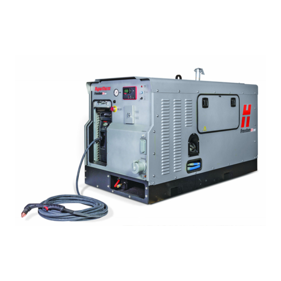
Sign In
Upload
Manuals
Brands
Hypertherm Manuals
Welding System
Freedom 38 PPA
Hypertherm Freedom 38 PPA Manuals
Manuals and User Guides for Hypertherm Freedom 38 PPA. We have
1
Hypertherm Freedom 38 PPA manual available for free PDF download: Service Manual
Hypertherm Freedom 38 PPA Service Manual (218 pages)
Large Autonomous Plasma Cutting System
Brand:
Hypertherm
| Category:
Welding System
| Size: 20.83 MB
Table of Contents
Table of Contents
7
Warranty
11
Attention
11
General
11
Patent Indemnity
11
Limitation of Liability
11
National and Local Codes
11
Liability Cap
12
Insurance
12
Transfer of Rights
12
Waterjet Product Warranty Coverage
12
Product
12
Parts Coverage
12
1 Troubleshooting
13
Where to Go for Help
13
System Components
16
Controls and Indicators
18
System Controller
18
Plasma Cutting System
20
Check Engine and Generator Status
21
Reset the Control System
21
System Faults
22
Active Faults and Cleared Faults
22
System Faults Triggered by Predefined Thresholds
23
Engine Faults (SPN and FMI Codes)
25
Find System Fault Codes in Events History
27
Troubleshoot Engine Issues
28
Reset Emergency Air Intake Shutoff Valve (if Equipped)
28
Engine will Not Start
29
Keep the Fuel System Clean
30
Use the Hand Pump to Bleed the Fuel System
31
Jump-Start the Battery
32
Common Engine and Generator Issues
35
Troubleshoot Air Flow Issues (Air Compressor)
36
Troubleshoot Power-Related Issues (Generator/Alternator)
38
Troubleshoot Plasma Cutting Issues
40
Common Cutting Issues
40
Plasma Cutting System Fault Codes and Solutions
41
Find Serial Numbers
47
Serial Number for the System
47
Serial Number for the Generator
48
Serial Number for the Engine
48
Serial Number for the Alternator
49
Serial Number and Version Numbers for the System Controller
50
Serial Number for the Air Compressor
51
Serial Number for the Plasma Cutting System
51
2 Routine Maintenance
53
Maintenance Schedules
53
Routine Maintenance Procedures
59
Every Use
60
Every Day
62
Every Week
63
Every Month
66
Every 3 Months (or 500 Operating Hours)
69
Every 6 Months
73
Every Year
78
Every 4,000 Operating Hours
81
3 System-Level Components
83
Remove and Install the System's Cover
86
Replace the Battery
89
Replace the Dynagen System Controller
92
Replace the Alternator Lamp
94
Replace the 12 V Circuit Breaker on the Front Panel
95
Replace the ON/OFF Power Switch
96
Replace Emergency Stop Contact Block
98
Replace Emergency Stop Button
99
Replace Front Panel Circuit Breaker
100
Replace the 480 V Auxiliary Outlet
102
Replace the Service Panel Compression Latch
104
Replace the 120 V Auxiliary Outlet
105
Replace 120 V Auxiliary Outlet Circuit Breaker
106
Replace the Front Panel
107
4 Plasma Components
111
Replace the Air Filter Element and Air Filter Bowl in the Plasma Supply
114
Detach the Plasma Supply Power Cord
115
Unfasten the Plasma Supply
118
5 Generator and Engine Components
121
Unfasten the Front Panel
124
Replace the Transformer
126
Replace the Emergency Air Intake Shut-Off Valve
130
Replace the Automatic Voltage Regulator (AVR)
133
Replace the Fuel-Level Sensor
136
Replace the AC Sensor Wiring Harnesses
138
Replace the Control System Wiring Harness
140
Replace the Generator Wiring Harness
142
Replace the Engine Wiring Harness
148
Replace the Relays
150
Replace the Fuel Shutoff Relay
151
Replace the Cooling Unit Fan Relay
152
Replace the Generator Rectifiers
153
6 Air Compression Components
155
Replace the Air Compressor Belt
160
Replace the Air Compressor and Drive Pulley
161
Replace the Compressor Tension Pulley
165
Replace the Compressor Inlet Valve
166
Replace the Air Compressor Temperature Switch, Tee Fitting, Elbow Fitting, and Adapter
167
Replace the Air Compressor Check Valve and Scavenge Line Orifice
169
Replace the Air Pressure Gauge
171
Replace the Unloader Valve
172
Replace the Muffler and Orifice Adapter
174
Replace the Separation Tank
175
Replace the Separation Tank Manifold
178
Replace the Cooler Unit
181
Replace the Compressor Cooling Fan
183
Replace the Pressure Relief Valve on the Separation Tank
185
Replace the Oil Level Gauge
186
Replace the Air Drying Filter Assembly
187
Replace the Pressure Relief Valve on the Air Drying Filter Assembly
190
Replace the Ball Valve, Elbow Fitting, and Elbow Coupler on the Separation Tank
191
Replace the Condensate Release Lever
193
7 Parts
195
System Parts
196
Exterior, Front Panel
196
Exterior, Sides
198
Interior, Engine and Generator
199
Wiring Harnesses
202
Interior, Air Compression System
204
Air Compression Hoses
207
Plasma Torches
209
Hand Torches
209
Machine Torches
210
Plasma Torch Consumables
211
Hand Cutting
211
Mechanized Cutting
212
Accessory Parts for Plasma Cutting
213
8 Wiring Diagrams
215
AC Wiring Diagram
217
12 VDC Wiring Diagram
218
Advertisement
Advertisement
Related Products
Hypertherm powermax 380
Hypertherm powermax 350
Hypertherm Powermax 30
Hypertherm 228723
Hypertherm Categories
Welding System
Cutter
Flashlight
Industrial Equipment
Controller
More Hypertherm Manuals
Login
Sign In
OR
Sign in with Facebook
Sign in with Google
Upload manual
Upload from disk
Upload from URL