Table of Contents
Advertisement
Quick Links
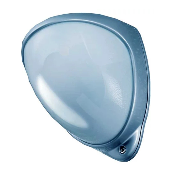
D-TECT 50
GJD350 50m Quad PIR Detector
PACKAGE CONTENTS
•
1 x D-TECT 50
•
1 x Drilling template for fixing holes
•
3 x 31.75mm wall plugs
•
3 x 31.75mm screws
•
2 x Tamper feet
•
1 x Tamper cup
•
1 x Creep mirror
•
1 x Installation manual
•
1 x 5m wide Fresnel lens (Lens 2, Fig.15)
INTRODUCTION
The D-TECT 50 is an outdoor motion detector and alarm
trigger that uses two independent passive infra-red
detectors, both of which must trigger to cause the detector
to signal an alarm. Utilising quad PIR technology, the
D-TECT 50 delivers precise, reliable presence detection.
QUICK INSTALLATION
1.
Mount and connect the detector following the
instructions given later in this sheet.
2.
Apply supply voltage to the unit. The detection LED
(blue) flashes three times.
3.
Wait approximately 2 to 3 minutes to allow the
detector to settle.
4.
Press the programming button once to activate walk
test mode. The detection LED is now enabled for five
minutes.
Note: The front cover must be fitted when walk testing.
The default settings are:
•
Range: 40 meters
•
Pulse count: 1 (always set to 1 during walk rest)
•
Detection LED: off (always enabled during Walk Test)
•
'S' Lux Level: 5
•
Contacts:
•
Alarm 1: Normally Closed
•
Alarm 2: Normally Open
•
Contacts Timer: 5 seconds
MOUNTING THE UNIT
WARNING
•
NYLON WASHERS PROVIDED MUST BE USED
WITH SCREWS
•
ENSURE CABLE ENTRY AND SCREW HOLES
ARE SEALED WITH WATER BASED SEALANT
•
DO NOT USE SILICONE BASED SEALANT
During installation, protect the electronics against water, as
trapped moisture can affect or damage the unit.
1.
Drill the wall to accept the two fixing screws, the
cable entry, and the tamper cup (if used). See Figure
1 and 2. A hole-drilling template is provided.
Note: We recommend using the tamper cup on uneven
wall surfaces.
2.
Remove the cover assembly by loosening the locking
screw. The cover hinges from the top and lifts out of
the location slot. See Figure 3.
3.
Feed standard eight-core alarm cable into the cable
entry. Bare the wires and connect to the top PCB
terminal block. See Figures 2, 4, 5 & 6.
4.
Screw the unit to the wall ensuring that the rear
tamper pin is correctly located and that the tamper
microswitch is closed.
To aid installation, two spare tamper feet are provided. One
is 1mm longer, the other is 2mm longer than the foot
originally fitted. The tamper foot is push fit and can be
removed by carefully pulling it from the pin. See Figure 2.
5.
When the detector is aligned, connected, and
programmed to suit the installation, replace the front
cover and lock as shown. See Figure 7.
CONNECTING THE UNIT
The D-TECT 50 includes jumpers that allow you to
configure the internal end-of-line resistor values, when EOL
resistors are required. Values are 1K, 2K2, 3K3, 4K7, 5K6
and 6K8 Ω.
Figure 8 shows:
1. EOL resistor jumpers
2. Wiring points
Alternatively, you can remove the jumpers and connect a
discrete resistor directly to the alarm or tamper outputs, as
specified by the third-party equipment.
Terminal
Label
1
A
2
S
3, 4
ALARM 1
4, 5
EOL
5, 6
TAMPER N/C
7, 8
ALARM 2
9, 10
9-24V
1
Description
24 hour -VE Output
Dark -VE Output
Alarm relay 1
End-of-line
resistors
Tamper relay,
normally closed
Alarm relay 2
AC / DC Supply
Advertisement
Table of Contents

Related Manuals for GJD D-TECT 50


Summary of Contents for GJD D-TECT 50
- Page 1 See Figures 2, 4, 5 & 6. INTRODUCTION Screw the unit to the wall ensuring that the rear The D-TECT 50 is an outdoor motion detector and alarm tamper pin is correctly located and that the tamper trigger that uses two independent passive infra-red microswitch is closed.
- Page 2 BEAM ALIGNMENT To change any of the D-TECT 50 settings: PIR circuitry detects changes in heat and movement in the beam pattern. Objects such as trees, shrubs, Press the program button, as shown in figure 13, for ponds, flues, and animals should be considered when the number of the Option to be changed, i.e.
- Page 3 Two Fresnel lenses giving up to and the pulse count option is set to 1. The detection LED 50m x 5m or 50m x 10m (Standard) lights each time the D-TECT 50 detects your presence. Adjustment 180° pan + 90° tilt...
- Page 5 Max. 2.6m...
- Page 6 ENGINEER NOTES www.gjd.co.uk info@gjd.co.uk +44 (0) 1706 363 998 Unit 2 Birch Business Park, Whittle Lane, Heywood, Greater Manchester, OL10 2SX, UK...
Need help?
Do you have a question about the D-TECT 50 and is the answer not in the manual?
Questions and answers