Table of Contents
Advertisement
Quick Links
Advertisement
Table of Contents

Related Manuals for Juniper JATP400


Summary of Contents for Juniper JATP400
- Page 1 JATP400 Appliance Hardware Guide Published 2021-05-17...
- Page 2 The Juniper Networks product that is the subject of this technical documentation consists of (or is intended for use with) Juniper Networks software. Use of such software is subject to the terms and conditions of the End User License Agreement ("EULA") posted at https:/ /support.juniper.net/support/eula/.
-
Page 3: Table Of Contents
Additional Hardware Requirements | 21 Initial Installation and Configuration JATP400 Installation Overview | 25 Overview of Installing the JATP400 Appliance in a Rack | 25 Tools and Parts Required for Installing the JATP400 Appliance | 25 Unpacking the JATP400 | 26... - Page 4 Maintaining JATP400 Power System | 52 Maintaining the JATP400 Power Supply | 52 Replacing an AC Power Supply on the JATP400 Appliance | 52 Replacing AC Power Supply Cables on the JATP400 Appliance | 53 Replacing a DC Power Supply on the JATP400 Appliance | 54...
- Page 5 Returning the Chassis or Components Returning the JATP400 Chassis or Components | 63 Locating the Serial Number on a JATP400 Chassis | 63 Contacting Customer Support to Obtain Return Material Authorization | 63 Packing a JATP400 for Shipping | 64...
- Page 6 DC Power Wiring Terminations Warning | 100 Multiple Power Supplies Disconnection Warning | 101 TN Power Warning | 102 JATP400 Agency Approvals and Compliance Statements | 103 Agency Approvals for the JATP400 Appliance | 103 Compliance Statements for Acoustic Noise for the JATP400 Appliance | 106...
-
Page 7: About This Guide
Use this guide to install hardware and perform initial software configuration, routine maintenance, and troubleshooting for the Juniper Networks Advanced Threat Prevention 400 (JATP400) appliance. After completing the installation and basic configuration procedures covered in this guide, refer to the JATP Software documentation for information about further software configuration. -
Page 8: Overview
C HAPTER Overview JATP400 System Overview | 2 JATP400 Chassis | 4... -
Page 9: Jatp400 System Overview
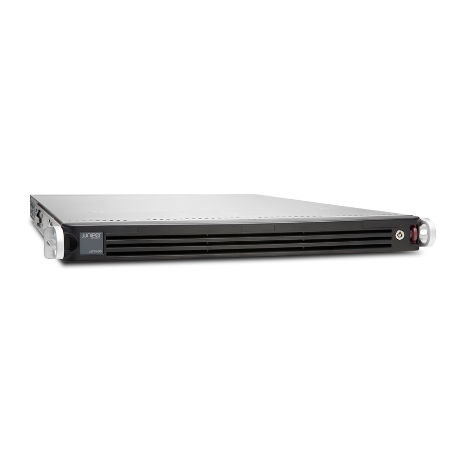
The appliance can be deployed as a Core device, Traffic Collector, Email Collector, Manager of Central Managers (MCM), Secondary Core, or as an All-In-One device. The JATP400 appliance is a 1-rack-unit (1-U), rack-mountable chassis with hot-swappable dual AC power supplies (or optional dual DC power supplies), four hot-swappable hard disk drives that support RAID, 32-GB memory, two 10-Gigabit Ethernet interfaces, two 10-Gigabit Ethernet SFP+ interfaces, and four 1-Gigabit Ethernet interfaces. -
Page 10: Jatp400 Appliance Transceiver Interface
JATP400 Appliance Transceiver Interface Two 10-Gigabit Ethernet SFP+ ports on the rear panel of the JATP400 appliance support SFP+ transceivers. Table 1 on page 3 lists the details of supported transceiver type. -
Page 11: Jatp400 Chassis
RELATED DOCUMENTATION JATP400 Chassis | 4 Overview of Preparing the Site for the JATP400 | 17 JATP400 Installation Overview | 25 JATP400 Chassis IN THIS SECTION JATP400 Appliance Front Panel Description | 4 JATP400 Appliance Back Panel Description | 10... - Page 12 Table 2: JATP400 Front Panel Components Callout Component Description Front Bezel Protects the appliance. Lock Locks the appliance. Chassis LEDs Provides the colors and states, and the status they indicate. RESET button Reboots the appliance. Power button Powers on or powers off the appliance.
- Page 13 Figure 2 on page 6 shows the front panel LEDs of the JATP400 appliance. Figure 2: JATP400 Front Panel LEDs Table 3 on page 6 lists the front panel LEDs of the JATP400 appliance. Table 3: JATP400 Front Panel LEDs...
- Page 14 (Continued) Table 3: JATP400 Front Panel LEDs Callout LEDs Description Information • Solid red—Indicates an overheat condition, which might be caused due to cable congestion. TIP: Check the routing of the cables if they are obstructing the airflow from the system.
- Page 15 (Continued) Table 3: JATP400 Front Panel LEDs Callout LEDs Description GLAN1 • Flashing—Indicates network activity on LAN port 1. • Steady—Indicates link. Hard drive Indicates activity on a hard drive when flashing. Power For AC power supply: • Solid green—Indicates that the appliance is receiving power.
- Page 16 Table 4 on page 9 lists the JATP400 hard disk drive port LEDs. Table 4: JATP400 HDD Port LEDs LEDs Description Activity (top) • Solid green—Indicates that the SAS drive is installed. • Green (blinking)—Indicates the I/O activity. Status (bottom) •...
-
Page 17: Jatp400 Appliance Back Panel Description
JATP400 Appliance Back Panel Description Figure 3 on page 10 shows the back panel components of the JATP400 appliance. Figure 3: JATP400 Back Panel Table 5 on page 10 lists the back panel components of the JATP400 appliance. Table 5: JATP400 Back Panel Components... - Page 18 (Continued) Table 5: JATP400 Back Panel Components Callout Components Description 1-Gigabit Ethernet LAN port RJ-45 port, eth0, management interface. 1-Gigabit Ethernet LAN port RJ-45 port, eth4. eth1 when this port is used as 1- Gigabit Ethernet copper port. 1-Gigabit Ethernet LAN port RJ-45 port, eth2, alternate exhaust interface.
- Page 19 Port 2 of USB 2.0. COM port One DB-9 COM port. NOTE: This port is not supported. Figure 4 on page 12 shows the back panel 10-Gigabit Ethernet port LEDs of the JATP400 appliance. Figure 4: JATP400 10-Gigabit Ethernet Port LEDs...
- Page 20 • Off—Indicates no traffic. Figure 5 on page 13 shows the back panel 1-Gigabit Ethernet port LEDs of the JATP400 appliance. Figure 5: JATP400 1-Gigabit Ethernet Port LEDs Table 7 on page 13 lists the JATP400 1-Gigabit Ethernet port LEDs.
- Page 21 (Continued) Table 7: JATP400 1-Gigabit Ethernet Port LEDs Callout LEDs Description Link • Solid amber—Indicates that the speed of the connection is 1000 Mbps. • Solid green—Indicates that the speed of the connection is 100 Mbps. Table 8 on page 14 lists the JATP400 IPMI port LEDs.
- Page 22 RELATED DOCUMENTATION JATP400 System Overview | 2 JATP400 Site Guidelines and Requirements | 17 JATP400 Installation Overview | 25...
-
Page 23: Site Planning, Preparation, And Specifications
C HAPTER Site Planning, Preparation, and Specifications Overview of Preparing the Site for the JATP400 | 17 JATP400 Site Guidelines and Requirements | 17... -
Page 24: Overview Of Preparing The Site For The Jatp400
6. Verify that the plan for power installation meets all electrical safety guidelines. 7. Verify that your rack meets the minimum requirements for the installation of the JATP400 appliance. 8. Plan to secure the rack to the floor and building structure. -
Page 25: General Site Installation Guidelines For The Jatp400 Appliance
General Site Installation Guidelines for the JATP400 Appliance The following precautions can help you plan an acceptable operating environment for your JATP400 appliance and avoid equipment failures caused by environmental factors: • For the cooling system to function properly, the airflow around the chassis must be unrestricted. - Page 26 (Continued) Table 10: JATP400 Appliance Physical Specifications Specification JATP400 Panel Display • UID button • LEDs: Information, Network activity, Hard drive activity, and Power • Reset button • Power button Rack mountable Four-post Ports • Two RJ-45 10-Gigabit Ethernet LAN ports •...
-
Page 27: Jatp400 Appliance Rack And Clearance Requirements
Maximum thermal output 1002.2 BTU/hour JATP400 Appliance Rack and Clearance Requirements You can install the JATP400 appliance in a four-post rack. Table 11 on page 20 provides the requirements for rack size, clearance, airflow, spacing of mounting brackets and flange holes, and connecting to the building structure. -
Page 28: Additional Hardware Requirements
1.25-in. (3.2 cm) apart (top and bottom mounting hole). Connecting to the Always secure the rack in which you are installing the JATP400 appliance to the building structure structure of the building. If your geographical area is subject to earthquakes, bolt the rack to the floor. - Page 29 Table 12: Required Ports Direction Default TCP/UDP Description Internet Depends on Port Configuratio command- line managemen Secure HTTP/ HTTPS. Used for connecting interface and APIs connection to new managed device TCP, UDP lookups System security updates from Juniper Networks...
- Page 30 Default TCP/UDP Description Internet Depends on Port Configuratio NTP time synchronizat SIEM/Syslog CEF server Juniper SRX Firewall NOTE: For Mitigation through SRX Firewall RELATED DOCUMENTATION Overview of Preparing the Site for the JATP400 | 17 JATP400 Installation Overview | 25...
-
Page 31: Initial Installation And Configuration
Unpacking the JATP400 | 26 Installing the JATP400 in a Rack | 29 Connecting the JATP400 to Power | 35 Connecting the JATP400 Appliance to a Management Device | 38 Performing the Initial Software Configuration for the JATP400 | 39 Configuring IPMI | 46... -
Page 32: Jatp400 Installation Overview
Tools and Parts Required for Installing the JATP400 Appliance | 25 Overview of Installing the JATP400 Appliance in a Rack You must proceed through the installation process in the following order: • Review all safety guidelines and warnings for the JATP400 appliance. See, "General Safety Guidelines and Warnings" on page •... -
Page 33: Unpacking The Jatp400
Table 13: Required Tools and Parts for Installing the JATP400 Appliance Task Tools and Parts Installing the JATP400 Appliance • Phillips (+) screwdriver, number 1 • Phillips (+) screwdriver, number 3 • Tie wrap Connecting the JATP400 Appliance ESD grounding wrist strap... -
Page 34: Unpacking The Jatp400
"Verifying the JATP400 Parts Received" on page Verifying the JATP400 Parts Received The JATP400 appliance shipment package contains a packing list. Check the parts in the shipment against the items on the packing list. The packing list specifies the part numbers and carries a brief description of each part in your order. - Page 35 / www.juniper.net/support/requesting-support.html. Table 14 on page 28 lists the JATP400 parts received through shipment. Table 14: Parts List for a JATP400 Appliance Part Quantity JATP400 appliance End User License Agreement...
-
Page 36: Installing The Jatp400 In A Rack
Figure 6: Identifying the Inner, Middle, and Outer Rails Inner rail Middle rail — — Locking tab Outer rail — — To install the JATP400 appliance: 1. To mount the JATP400 appliance in a four-post rack: a. Install the inner rail extensions. - Page 37 Secure the inner rails to the chassis with the screws provided. Figure 7: Installing the Inner Rails NOTE: Each inner rail of the JATP400 appliance has a locking tab. The locking tabs secure the chassis when either it is installed or completely extended from the rack.
- Page 38 Insert the front hooks of the outer rails into the front slots of the rack, and use the M5 screws to secure the front of the outer rails to the rack, as shown in Figure 8 on page Figure 8: Inserting the Front Mounting Rails iii.
- Page 39 Insert the rear hooks of the outer rails into the rear slots of the rack, and use the screws to secure the rear of the outer rails to the rack, as shown in Figure 9 on page Figure 9: Inserting the Front and Rear Mounting Rails c.
- Page 40 e. Align the chassis inner rails with the ball-bearing shuttle, as shown in Figure 10 on page Figure 10: Aligning the Chassis Rails with the Ball-Bearing Shuttle f. Apply even pressure on both sides; slide the chassis inner rails into the middle rails until the locking tab of the inner rail clicks into the front of the middle rail, locking the chassis into the fully extended position.
- Page 41 5. Connect the monitor to VGA port and the keyboard to USB port on the back panel. For more information, see "Connecting the JATP400 Appliance to a Management Device" on page 6. Push the power button on the front panel.
-
Page 42: Connecting The Jatp400 To Power
• Ensure that you have taken the necessary precautions to prevent electrostatic discharge (ESD) damage. • Ensure that you have connected the JATP400 appliance chassis to earth ground, if required by your site guidelines or installation. CAUTION: For installations that require a separate grounding conductor to the chassis, have a licensed electrician complete this connection before you connect the appliance to power. - Page 43 • ESD grounding strap. • Power cord or cords appropriate for your geographical location. CAUTION: Before you connect power to the JATP400 appliance, ensure both power supply ground terminals are grounded to meet the safety requirements and to ensure proper operation.
-
Page 44: Connecting Dc Power To The Jatp400 Appliance
Before connecting your JATP400 appliance to a DC power source: • Ensure that you have taken the necessary precautions to prevent ESD damage. • Ensure that you have connected the JATP400 appliance chassis to earth ground, if required by your site guidelines or installation. -
Page 45: Connecting The Jatp400 Appliance To A Management Device
2. Connect the black wire to the -48 V terminal block and red wire to the RTN terminal block on the back panel of the JATP400 appliance. 3. Use the terminal screws to secure the power source cables to the power feed on the JATP400 appliance. -
Page 46: Performing The Initial Software Configuration For The Jatp400
JATP400 Installation Overview | 25 Performing the Initial Software Configuration for the JATP400 IN THIS SECTION Selecting the Form Factor | 39 Configuring the IP Address and Domain Name Servers | 41 Configuring the Device Host Name | 41 Configuring the Alternate Exhaust Interface | 42... - Page 47 Juniper Networks Advanced Threat Prevention window appears. See Figure 14 on page NOTE: By default, the JATP400 is installed as an All-In-One appliance. Figure 14: Juniper Networks Advanced Threat Prevention Window Type Yes if you want to change the appliance form factor.
-
Page 48: Configuring The Ip Address And Domain Name Servers
NOTE: The network interface restart can take up to 60 seconds or more. Configuring the Device Host Name To configure the device host name: 1. Enter a valid hostname. For example, JATP400. NOTE: Enter a unique name for the host and do not include the domain. Updates server to JATP400.example.com. -
Page 49: Configuring The Alternate Exhaust Interface
Figure 15: Setting Device Host Name NOTE: If you decline the self-signed certificate by entering No, the JATP400 appliance will continue to use the existing certificates. These certificates might contain an incorrect hostname or fully qualified domain name (FQDN). To resolve this issue on the Web UI, regenerate a new self-signed SSL certificate or upload your private key and certificate. -
Page 50: Configuring The Device Basic Attributes
Configuring the Device Basic Attributes To configure basic server attributes: 1. Type Yes if the device is a Core, an All-In-One, or a Manager of Central Managers (MCM) system. See Figure 16 on page NOTE: If your device is a Traffic Collector, a Secondary Core, or an Email Collector, type No and enter the Core or All-In-One IP address. -
Page 51: Accessing The Jatp Interface
1. Open your Web browser. 2. Log in to your JATP appliance: https:/ / <IP Address> <IP Address> is the IP address of the JATP appliance. Where 3. Enter the default username admin and the default password juniper. See Figure 17 on page... - Page 52 Figure 17: Advanced Threat Prevention Appliance Login Screen 4. Click Log In. The JATP interface appears. RELATED DOCUMENTATION JATP400 Installation Overview | 25 Connecting the JATP400 to Power | 35 Connecting the JATP400 Appliance to a Management Device | 38...
-
Page 53: Configuring Ipmi
Configuring IPMI Intelligent Platform Management Interface (IPMI) is a message-based hardware management interface that enables remote monitoring, management, and recovery capabilities, regardless of the status of the server. It defines a set of interfaces that are common to computer hardware and firmware that you can use to monitor system health and manage the system. - Page 54 Select Yes for Update IPMI LAN Configuration and press Enter. See Figure 19 on page Figure 19: Updating IPMI LAN Configuration Select Static for Configuration Address Source and press Enter. See Figure 19 on page Assign the values for the following fields: •...
- Page 55 Select Save & Exit > Save Changes and Reset and press Enter. See Figure 20 on page Figure 20: Saving IPMI Settings and Exiting the BIOS Setup Configure your laptop IP address. For example, see Figure 21 on page...
- Page 56 Your laptop and the JATP400 IPMI are in the same subnet. Figure 21: Configuring Laptop IPv4 Settings Connect the IPMI port on the back panel of the JATP400 appliance and the laptop LAN port with a CAT5 Ethernet cable. 10. Open your Web browser.
- Page 57 NOTE: Username and password are not case sensitive. Figure 22: JATP IPMI Login Screen 13. Click Login. The JATP interface appears. RELATED DOCUMENTATION JATP400 Chassis | 4 Connecting the JATP400 Appliance to a Management Device | 38 Performing the Initial Software Configuration for the JATP400 | 39...
-
Page 58: Maintaining Components
C HAPTER Maintaining Components Maintaining JATP400 Power System | 52 Maintaining the JATP400 Hard Disk Drive | 56... -
Page 59: Maintaining Jatp400 Power System
• Routinely check the power LED on the power supply module. If the LED status is green, the power supply is functioning normally. • Periodically inspect the site to ensure that the power cables connected to the JATP400 appliance are securely in place and moisture is not accumulating near the appliance. -
Page 60: Replacing Ac Power Supply Cables On The Jatp400 Appliance
Attach the power cord to the power supply. If the power supply is correctly installed and functioning normally, the power supply powers up immediately. Replacing AC Power Supply Cables on the JATP400 Appliance To replace an AC power supply cord: 1. -
Page 61: Replacing A Dc Power Supply On The Jatp400 Appliance
8. If the power supply is correctly installed and functioning normally, the supply automatically powers Replacing a DC Power Supply on the JATP400 Appliance To replace a DC power supply: 1. To remove the DC power supply: a. -
Page 62: Replacing Dc Power Supply Cables On The Jatp400 Appliance
Close the input circuit breaker. The device powers on as soon as power is provided to the power supply. Replacing DC Power Supply Cables on the JATP400 Appliance To replace a DC power supply cable: 1. Attach an ESD grounding strap to your bare wrist and connect the strap to one of the ESD points on the chassis. -
Page 63: Maintaining The Jatp400 Hard Disk Drive
• Error correction—Redundant data storage to detect and resolve problems The JATP400 appliance ships with hot-swappable hard disks to offer component redundancy. The JATP400 appliance uses the RAID6 configuration. In RAID6, drives are duplicated for fault tolerance. Replacing a Hard Drive on the JATP400 Appliance To replace a hard drive from a driver carrier on the JATP400 appliance: 1. - Page 64 The hard drive pops partially out of the slot.
- Page 65 Figure 24: Removing a Drive Carrier...
- Page 66 This indicates that the carrier has been fully seated and connected to the midplane, which automatically makes the power and logic connections to the hard drive. RELATED DOCUMENTATION Contacting Juniper Networks Technical Assistance Center | 61 JATP400 Chassis | 4 Connecting the JATP400 to Power | 35...
-
Page 67: Troubleshooting Hardware
C HAPTER Troubleshooting Hardware Contacting Juniper Networks Technical Assistance Center | 61... -
Page 68: Contacting Juniper Networks Technical Assistance Center
Contacting Juniper Networks Technical Assistance Center You can contact Juniper Networks Technical Assistance Center (JTAC) 24 hours a day, 7 days a week in one of the following ways: • On the Web, using the Case Manager link at: https:/ /www.juniper.net/support/ •... -
Page 69: Returning The Chassis Or Components
C HAPTER Returning the Chassis or Components Returning the JATP400 Chassis or Components | 63... -
Page 70: Returning The Jatp400 Chassis Or Components
The serial number ID of the JATP400 appliance is located on a label on the back of the chassis. You must provide the serial number to the Juniper Networks Technical Assistance Center (JTAC) when you contact them to obtain a Return Materials Authorization (RMA). -
Page 71: Packing A Jatp400 For Shipping
Packing a JATP400 for Shipping To pack a JATP400 appliance for shipping: 1. Power off the JATP400 appliance and remove the AC power cords or DC power cables. 2. Remove the cables that connect the JATP400 appliance to all external devices. - Page 72 Maintaining the JATP400 Hard Disk Drive | 56...
-
Page 73: Safety And Compliance Information
Warning Statement for Norway and Sweden | 71 Fire Safety Requirements | 72 Installation Instructions Warning | 73 Chassis Lifting Guidelines for the JATP400 Appliance | 74 Restricted Access Warning | 74 Ramp Warning | 76 Rack-Mounting and Cabinet-Mounting Warnings | 76... - Page 74 DC Power Grounding Requirements and Warning | 98 DC Power Wiring Sequence Warning | 99 DC Power Wiring Terminations Warning | 100 Multiple Power Supplies Disconnection Warning | 101 TN Power Warning | 102 JATP400 Agency Approvals and Compliance Statements | 103...
-
Page 75: General Safety Guidelines And Warnings
General Safety Guidelines and Warnings The following guidelines help ensure your safety and protect the device from damage. The list of guidelines might not address all potentially hazardous situations in your working environment, so be alert and exercise good judgment at all times. •... -
Page 76: Definitions Of Safety Warning Levels
• Some parts of the chassis, including AC and DC power supply surfaces, power supply unit handles, SFB card handles, and fan tray handles might become hot. The following label provides the warning of the hot surfaces on the chassis: •... - Page 77 dient u zich bewust te zijn van de bij elektrische schakelingen betrokken risico's en dient u op de hoogte te zijn van standaard maatregelen om ongelukken te voorkomen. Varoitus Tämä varoitusmerkki merkitsee vaaraa. Olet tilanteessa, joka voi johtaa ruumiinvammaan. Ennen kuin työskentelet minkään laitteiston parissa, ota selvää sähkökytkentöihin liittyvistä...
-
Page 78: Qualified Personnel Warning
Qualified Personnel Warning WARNING: Only trained and qualified personnel should install or replace the device. Waarschuwing Installatie en reparaties mogen uitsluitend door getraind en bevoegd personeel uitgevoerd worden. Varoitus Ainoastaan koulutettu ja pätevä henkilökunta saa asentaa tai vaihtaa tämän laitteen. Avertissement Tout installation ou remplacement de l'appareil doit être réalisé... -
Page 79: Fire Safety Requirements
In addition, you should establish procedures to protect your equipment in the event of a fire emergency. Juniper Networks products should be installed in an environment suitable for electronic equipment. We recommend that fire suppression equipment be available in the event of a fire in the vicinity of the equipment and that all local fire, safety, and electrical codes and ordinances be observed when you install and operate your equipment. -
Page 80: Installation Instructions Warning
NOTE: To keep warranties effective, do not use a dry chemical fire extinguisher to control a fire at or near a Juniper Networks device. If a dry chemical fire extinguisher is used, the unit is no longer eligible for coverage under a service agreement. -
Page 81: Chassis Lifting Guidelines For The Jatp400 Appliance
Chassis Lifting Guidelines for the JATP400 Appliance The weight of a fully loaded JATP400 appliance is approximately 36 lb (16.33 kg). Observe the following guidelines for lifting and moving a JATP400 appliance: • Before installing the appliance, read the guidelines in "JATP400 Site Guidelines and Requirements"... - Page 82 Varoitus Tämä laite on tarkoitettu asennettavaksi paikkaan, johon pääsy on rajoitettua. Paikka, johon pääsy on rajoitettua, tarkoittaa paikkaa, johon vain huoltohenkilöstö pääsee jonkin erikoistyökalun, lukkoon sopivan avaimen tai jonkin muun turvalaitteen avulla ja joka on paikasta vastuussa olevien toimivaltaisten henkilöiden valvoma. Avertissement Cet appareil est à...
-
Page 83: Ramp Warning
Ramp Warning WARNING: When installing the device, do not use a ramp inclined at more than 10 degrees. Waarschuwing Gebruik een oprijplaat niet onder een hoek van meer dan 10 graden. Varoitus Älä käytä sellaista kaltevaa pintaa, jonka kaltevuus ylittää 10 astetta. Avertissement Ne pas utiliser une rampe dont l'inclinaison est supérieure à... - Page 84 Les directives ci-dessous sont destinées à assurer la protection du personnel: • Le rack sur lequel est monté le Juniper Networks switch doit être fixé à la structure du bâtiment.
- Page 85 Le seguenti direttive vengono fornite per garantire la sicurezza personale: • Il Juniper Networks switch deve essere installato in un telaio, il quale deve essere fissato alla struttura dell'edificio. • Questa unità deve venire montata sul fondo del supporto, se si tratta dell'unica unità...
- Page 86 Para garantizar su seguridad, proceda según las siguientes instrucciones: • El Juniper Networks switch debe instalarse en un bastidor fijado a la estructura del edificio. • Colocar el equipo en la parte inferior del bastidor, cuando sea la única unidad en el...
-
Page 87: Grounded Equipment Warning
Följande riktlinjer ges för att trygga din säkerhet: • Juniper Networks switch måste installeras i en ställning som är förankrad i byggnadens struktur. • Om denna enhet är den enda enheten på ställningen skall den installeras längst ned på... -
Page 88: Radiation From Open Port Apertures Warning
Avvertenza Questo dispositivo deve sempre disporre di una connessione a massa. Seguire le istruzioni indicate in questa guida per connettere correttamente il dispositivo a massa. Advarsel Denne enheten på jordes skikkelig hele tiden. Følg instruksjonene i denne veiledningen for å jorde enheten. Aviso Este equipamento deverá... -
Page 89: Laser And Led Safety Guidelines And Warnings
Class 1 LED Product Warning | 84 Laser Beam Warning | 84 Juniper Networks devices are equipped with laser transmitters, which are considered a Class 1 Laser Product by the U.S. Food and Drug Administration and are evaluated as a Class 1 Laser Product per EN 60825-1 requirements. - Page 90 General Laser Safety Guidelines When working around ports that support optical transceivers, observe the following safety guidelines to prevent eye injury: • Do not look into unterminated ports or at fibers that connect to unknown sources. • Do not examine unterminated optical ports with optical instruments. •...
- Page 91 Class 1 LED Product Warning LASER WARNING: Class 1 LED product. Waarschuwing Klasse 1 LED-product. Varoitus Luokan 1 valodiodituote. Avertissement Alarme de produit LED Class I. Warnung Class 1 LED-Produktwarnung. Avvertenza Avvertenza prodotto LED di Classe 1. Advarsel LED-produkt i klasse 1. Aviso Produto de classe 1 com LED.
-
Page 92: Maintenance And Operational Safety Guidelines And Warnings
Aviso Não olhe fixamente para o raio, nem olhe para ele directamente com instrumentos ópticos. ¡Atención! No mirar fijamente el haz ni observarlo directamente con instrumentos ópticos. Varning! Rikta inte blicken in mot strålen och titta inte direkt på den genom optiska instrument. - Page 93 aanbevolen is. Gebruikte batterijen dienen overeenkomstig fabrieksvoorschriften weggeworpen te worden. Varoitus Räjähdyksen vaara, jos akku on vaihdettu väärään akkuun. Käytä vaihtamiseen ainoastaan saman- tai vastaavantyyppistä akkua, joka on valmistajan suosittelema. Hävitä käytetyt akut valmistajan ohjeiden mukaan. Avertissement Danger d'explosion si la pile n'est pas remplacée correctement. Ne la remplacer que par une pile de type semblable ou équivalent, recommandée par le fabricant.
- Page 94 Waarschuwing Alvorens aan apparatuur te werken die met elektrische leidingen is verbonden, sieraden (inclusief ringen, kettingen en horloges) verwijderen. Metalen voorwerpen worden warm wanneer ze met stroom en aarde zijn verbonden, en kunnen ernstige brandwonden veroorzaken of het metalen voorwerp aan de aansluitklemmen lassen.
- Page 95 Varning! Tag av alla smycken (inklusive ringar, halsband och armbandsur) innan du arbetar på utrustning som är kopplad till kraftledningar. Metallobjekt hettas upp när de kopplas ihop med ström och jord och kan förorsaka allvarliga brännskador; metallobjekt kan också sammansvetsas med kontakterna. Lightning Activity Warning WARNING: Do not work on the system or connect or disconnect cables during periods of lightning activity.
- Page 96 6 in. (15.2 cm) of clearance around the ventilation openings. Waarschuwing Om te voorkomen dat welke switch van de Juniper Networks router dan ook oververhit raakt, dient u deze niet te bedienen op een plaats waar de maximale aanbevolen omgevingstemperatuur van 40°...
- Page 97 ¡Atención! Para impedir que un encaminador de la serie Juniper Networks switch se recaliente, no lo haga funcionar en un área en la que se supere la temperatura ambiente máxima recomendada de 40° C. Para impedir la restricción de la entrada de aire, deje un espacio mínimo de 15,2 cm alrededor de las aperturas para ventilación.
-
Page 98: General Electrical Safety Guidelines And Warnings
General Electrical Safety Guidelines and Warnings WARNING: Certain ports on the device are designed for use as intrabuilding (within- GR-1089-CORE ) the-building) interfaces only (Type 2 or Type 4 ports as described in and require isolation from the exposed outside plant (OSP) cabling. To comply with NEBS requirements and protect against lightning surges and commercial power must not be metallically connected to interfaces disturbances, the intrabuilding ports... -
Page 99: Action To Take After An Electrical Accident
• Canada—Canadian Electrical Code, Part 1, CSA C22.1. • Suitable for installation in Information Technology Rooms in accordance with Article 645 of the National Electrical Code and NFPA 75. Peut être installé dans des salles de matériel de traitement de l’information conformément à l’article 645 du National Electrical Code et à... -
Page 100: Prevention Of Electrostatic Discharge Damage
Prevention of Electrostatic Discharge Damage Device components that are shipped in antistatic bags are sensitive to damage from static electricity. Some components can be impaired by voltages as low as 30 V. You can easily generate potentially damaging static voltages whenever you handle plastic or foam packing material or if you move components across plastic or carpets. -
Page 101: Ac Power Electrical Safety Guidelines
• When removing or installing a component that is subject to ESD damage, always place it component- side up on an antistatic surface, in an antistatic card rack, or in an antistatic bag (see Figure 25 on page 94). If you are returning a component, place it in an antistatic bag before packing it. Figure 25: Placing a Component into an Antistatic Bag CAUTION: ANSI/TIA/EIA-568 cables such as Category 5e and Category 6 can get electrostatically charged. -
Page 102: Ac Power Disconnection Warning
“ATTENTION: CET APPAREIL COMPORTE PLUS D'UN CORDON D'ALIMENTATION. AFIN DE PRÉVENIR LES CHOCS ÉLECTRIQUES, DÉBRANCHER TOUT CORDON D'ALIMENTATION AVANT DE FAIRE LE DÉPANNAGE.” • AC-powered devices are shipped with a three-wire electrical cord with a grounding-type plug that fits only a grounding-type power outlet. Do not circumvent this safety feature. Equipment grounding must comply with local and national electrical codes. -
Page 103: Dc Power Disconnection Warning
Varoitus Kytke irti vaihtovirtalaitteiden virtajohto, ennen kuin teet mitään asennuspohjalle tai työskentelet virtalähteiden läheisyydessä. Avertissement Avant de travailler sur un châssis ou à proximité d'une alimentation électrique, débrancher le cordon d'alimentation des unités en courant alternatif. Warnung Bevor Sie an einem Chassis oder in der Nähe von Netzgeräten arbeiten, ziehen Sie bei Wechselstromeinheiten das Netzkabel ab bzw. - Page 104 Varoitus Varmista, että tasavirtapiirissä ei ole virtaa ennen seuraavien toimenpiteiden suorittamista. Varmistaaksesi, että virta on KATKAISTU täysin, paikanna tasavirrasta huolehtivassa kojetaulussa sijaitseva suojakytkin, käännä suojakytkin KATKAISTU- asentoon ja teippaa suojakytkimen varsi niin, että se pysyy KATKAISTU-asennossa. Avertissement Avant de pratiquer l'une quelconque des procédures ci-dessous, vérifier que le circuit en courant continu n'est plus sous tension.
-
Page 105: Dc Power Grounding Requirements And Warning
BRUTEN genom att slå AV det överspänningsskydd som skyddar likströmskretsen och tejpa fast överspänningsskyddets omkopplare i FRÅN-läget. DC Power Grounding Requirements and Warning An insulated grounding conductor that is identical in size to the grounded and ungrounded branch circuit supply conductors but is identifiable by green and yellow stripes is installed as part of the branch circuit that supplies the device. -
Page 106: Dc Power Wiring Sequence Warning
DC Power Wiring Sequence Warning WARNING: Wire the DC power supply using the appropriate lugs. When connecting power, the proper wiring sequence is ground to ground, +RTN to +RTN, then –48 V to – 48 V. When disconnecting power, the proper wiring sequence is –48 V to –48 V, +RTN to +RTN, then ground to ground. -
Page 107: Dc Power Wiring Terminations Warning
muele para moler, +RTN a +RTN, entonces –48 V a –48 V. Al desconectar potencia, la secuencia apropiada del cableado es –48 V a –48 V, +RTN a +RTN, entonces molió para moler. Observe que el alambre de tierra se debe conectar siempre primero y desconectar por último. -
Page 108: Multiple Power Supplies Disconnection Warning
Warnung Wenn Litzenverdrahtung erforderlich ist, sind zugelassene Verdrahtungsabschlüsse, z.B. für einen geschlossenen Regelkreis oder gabelförmig, mit nach oben gerichteten Kabelschuhen zu verwenden. Diese Abschlüsse sollten die angemessene Größe für die Drähte haben und sowohl die Isolierung als auch den Leiter festklemmen. -
Page 109: Tn Power Warning
Varoitus Tässä laitteessa on useampia virtalähdekytkentöjä. Kaikki kytkennät on irrotettava kokonaan, jotta virta poistettaisiin täysin laitteesta. Avertissement Cette unité est équipée de plusieurs raccordements d'alimentation. Pour supprimer tout courant électrique de l'unité, tous les cordons d'alimentation doivent être débranchés. Warnung Diese Einheit verfügt über mehr als einen Stromanschluß; um Strom gänzlich von der Einheit fernzuhalten, müssen alle Stromzufuhren abgetrennt sein. -
Page 110: Jatp400 Agency Approvals And Compliance Statements
JATP400 Agency Approvals and Compliance Statements IN THIS SECTION Agency Approvals for the JATP400 Appliance | 103 Compliance Statements for Acoustic Noise for the JATP400 Appliance | 106 Agency Approvals for the JATP400 Appliance JATP400 comply with the following standards: • Safety •... - Page 111 • IEC 60950-1:2005 (Second Edition); Am1:2009 + Am2:2013 All 60950-based standards to be evaluated using 2000m altitude • CE • EMC • FCC Part 15 Class A (2007) USA Radiated Emissions • EN 55022 Class A (2006) European Radiated Emissions •...
- Page 112 • Common Language Equipment Identifier (CLEI) code • FIPS requirements • FIPS 140-2 Level 1 • Regional country certifications • USA • Safety Certification - UL 60950-1 • EMC – FCC Class A • Network homologation –TIA-966 • Canada • Safety Certification - CSA 60950-1 •...
-
Page 113: Compliance Statements For Acoustic Noise For The Jatp400 Appliance
• Network homologation – CTR 12 /13, CTR21, DOC • NEBS — Not compliant Compliance Statements for Acoustic Noise for the JATP400 Appliance The maximum emitted sound pressure level is 65 dB(A) or less per EN ISO 7779. German Translation: Maschinenlärminformations-Verordnung - 3.
Need help?
Do you have a question about the JATP400 and is the answer not in the manual?
Questions and answers