Advertisement
Quick Links
The information contained in this document supersedes all similar information that
may be found elsewhere in this manual.
Service – Due to the sophisticated
nature of the sensors and associated
instrumentation
Piezotronics, user servicing or repair is
not recommended and, if attempted,
may void the factory warranty. Routine
maintenance, such as the cleaning of
electrical connectors, housings, and
mounting surfaces with solutions and
techniques that will not harm the
physical material of construction, is
acceptable. Caution should be observed
to ensure that liquids are not permitted
to migrate into devices that are not
hermetically
sealed.
should only be wiped with a dampened
cloth and never submerged or have
liquids poured upon them.
Repair – In the event that equipment
becomes
damaged
operate, arrangements should be made
to
return
the
Piezotronics for repair. User servicing or
repair is not recommended and, if
attempted,
may
warranty.
Calibration – Routine calibration of
sensors and associated instrumentation
is recommended as this helps build
confidence in measurement accuracy
and
acquired
calibration
cycles
established by the users own quality
regimen. When in doubt about a
calibration cycle, a good "rule of thumb"
is to recalibrate on an annual basis. It is
nbn Austria GmbH
provided
by
PCB
Such
devices
or
ceases
to
equipment
to
PCB
void
the
factory
data.
Equipment
are
typically
Service, Repair, and Return
Policies and Instructions
also good practice to recalibrate after
exposure to any severe temperature
extreme,
shock,
load,
environmental influence, or prior to any
critical test.
PCB Piezotronics maintains an ISO-
9001 certified metrology laboratory and
offers calibration services, which are
accredited by A2LA to ISO/IEC 17025,
with full traceability to SI through
N.I.S.T. In addition to the normally
supplied calibration, special testing is
also available, such as: sensitivity at
elevated or cryogenic temperatures,
phase response, extended high or low
frequency response, extended range,
leak
testing,
hydrostatic
testing, and others. For information on
standard
recalibration
special testing, contact your local PCB
Piezotronics
distributor,
representative,
or
factory
service representative.
Returning
Equipment
these procedures will ensure that your
returned materials are handled in the
most
expedient
manner.
returning
any
equipment
Piezotronics,
contact
distributor,
sales
representative,
factory customer service representative
to obtain a Return Warranty, Service,
Repair, and Return Policies and
Instructions
Materials
(RMA) Number. This RMA number
should be clearly marked on the outside
of all package(s) and on the packing
or
other
pressure
services
or
sales
customer
–
Following
Before
to
PCB
your
local
or
Authorization
Advertisement

Subscribe to Our Youtube Channel
Related Manuals for PCB Piezotronics IMI SENSORS 682A14


Summary of Contents for PCB Piezotronics IMI SENSORS 682A14
- Page 1 Piezotronics, user servicing or repair is critical test. not recommended and, if attempted, may void the factory warranty. Routine PCB Piezotronics maintains an ISO- maintenance, such as the cleaning of 9001 certified metrology laboratory and electrical connectors, housings, and offers calibration services, which are...
- Page 2 50% of the replacement cost returned PCB Piezotronics, Inc. item(s). PCB will provide a price quotation replacement 3425 Walden Ave. recommendation for any item whose...
- Page 3 RoHS2 PCB Industrial Monitoring and Measuring Equipment - China RoHS 2 Disclosure Table (Pb) (Cr(VI)) (PBB) (PBDE) (Hg) (Cd) SJ/T 11364 GB/T 26572 GB/T 26572 RoHS 2011/65/ EU CHINA RoHS COMPLIANCE...
- Page 4 Component Name Hazardous Substances Lead Mercury Cadmium Chromium VI Polybrominated Polybrominated (Pb) (Hg) (Cd) Compounds Biphenyls Diphenyl (Cr(VI)) (PBB) Ethers (PBDE) Housing PCB Board Electrical Connectors Piezoelectric Crystals Epoxy Teflon Electronics Thick Film Substrate Wires Cables Plastic Solder Copper Alloy/Brass This table is prepared in accordance with the provisions of SJ/T 11364.
- Page 5 PCB Piezotronics Inc. claims proprietary rights in REVISIONS the information disclosed hereon. Neither it nor any reproduction thereof will be disclosed to others DESCRIPTION without the written consent of PCB Piezotronics Inc. RELEASED TO DRAFTING 48166 4.47 [113.6] .50 [12.7] .890 [22.60]...
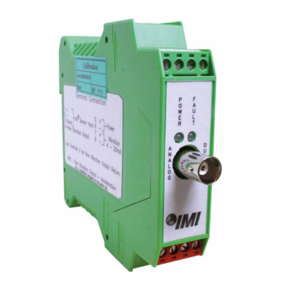
- Page 6 ® Model 682A14 & 682A15 4-20mA Din Rail ICP Signal Conditioner Operating Guide with Enclosed Warranty Information 3425 Walden Avenue, Depew, New York 14043-2495 Phone (716) 684-0003 Fax (716) 684-3823 Toll Free Line 1-800-959-4IMI MANUAL NUMBER: 72514 MANUAL REVISION: NR ECN NUMBER: 50075 nbn Austria GmbH...
-
Page 7: Table Of Contents
Table of Contents Introduction ........................Page 3 Block Diagram ......................Page 3 General Features Page 4 ............................Installation and Wiring ..................... Page 5 Configuring the 682A14 & 682A15 .................. Page 9 ESD Sensitivity ....................... Page 10 Warranty/Servicing Warranty, Service & Return Procedure ................Page 11 Customer Service ...................... -
Page 8: Introduction
Introduction Models 682A14 & 682A15 are 4-20mA din rail signal conditioners designed to interface with a 100 mV/g ICP ® accelerometer. The signal is integrated, filtered and scaled. The 4-20mA output signal is proportional to overall velocity with a measurement range of 0-1 ips rms when using the 682A15 and ips peak when using the 682A14. Block Diagram PAGE 3... -
Page 9: General Features
General Features External transmitters, signal conditioners and ICP power supplies can be eliminated by direct connection ® of the sensor to the din rail signal conditioner. 24Vdc unregulated/20Vdc regulated (field-selectable), 4mA excitation to power sensor. Current (4-20mA) output signal for long-term process monitoring. Analog output (raw vibration) signal for conducting frequency analysis and machinery diagnostics. -
Page 10: Installation And Wiring
Installation and Wiring Installation Models 682A14 & 682A15 are designed to be mounted on a 35mm din rail. Do not install in a harsh area where it can be exposed to cleaning fluids or machine oils. IMI Sensors recommends mounting models 682A14 & 682A15 in a NEMA 4 enclosure, such as Model 682A00, to protect the electronics from contamination. - Page 11 Connector and Pinout Diagram Models 682A14 & 682A15 use plug-in type screw terminal connectors for all input and output connections. This easy-to-assemble connection method allows devices to be exchanged easily and the electrical connection to be visibly isolated. Strip off 8mm of insulation from the connection wire ends. Using a flat head screwdriver, remove the terminal block from the enclosure.
- Page 12 Pin Descriptions: DC Power – Pins 5 and 6: Pin 5 + Power Pin 6 - Power (Common) ® Sensor Input – Pins 1, 2 and 3: Pin 1 + ICP Sensor Input ® Pin 2 - ICP Sensor Input ®...
- Page 13 Typical Wiring Diagram To maintain conformance, Earth Ground, power supply common, input shields and output shields must be connected together. PAGE 8...
-
Page 14: Configuring The 682A14 & 682A15
Configuring the 682A14 & 682A15 Sensor Power Jumper Configuration: Regulated 20Vdc/4mA Power (Factory Default) Unregulated 24Vdc/4mA Power (Constant Current Diode is internal to Model 682A14 & 682A15.) PAGE 9... -
Page 15: Esd Sensitivity
Warning 2 – ESD sensitivity This equipment is designed with user safety in mind; however, the protection provided by the equipment may be impaired if the equipment is used in a manner not specified by PCB Piezotronics, Inc. Caution 1 – ESD sensitivity Cables can kill your equipment. -
Page 16: Warranty, Service & Return Procedure
therefore be done ONLY at an ESD-safe work area. Many products have ESD protection, but the level of protection may be exceeded by extremely high voltage. Warranty IMI instrumentation is warranted against defective material and workmanship for 1 year unless otherwise expressly specified. -
Page 17: Customer Service
Customer Service IMI, a division of PCB Piezotronics, guarantees Total Customer Satisfaction. If, at any time, for any reason, you are not completely satisfied with any IMI product, IMI will repair, replace, or exchange it at no charge. You may also choose, within the warranty period, to have your purchase price refunded.
Need help?
Do you have a question about the IMI SENSORS 682A14 and is the answer not in the manual?
Questions and answers