
Related Manuals for Perkins 415GM


Summary of Contents for Perkins 415GM
- Page 1 Part No N39453 ® User’s Handbook 415GM 422GM 422TGM 4.4GM 4.4TGM 4.4TWGM & 4.4TW2GM 4.4GM & 4.4TGM 4.4TWGM & 4.4TW2GM Radiator Radiator...
- Page 3 © Proprietary information of Wimborne Marine Power Centre, all rights reserved. The information is correct at the time of print. Published in December 2013 by Wimborne Marine Power Centre, Wimborne, Dorset, England BH21 7PW Tel: +44(0)1202 796000 Fax: +44(0)1202 796001 E -mail: Marine@Perkins.com www.perkins.com/marine...
- Page 4 Title N39453...
-
Page 5: Table Of Contents
Rear and right side view (P) of the engine .............31 3 Operation instructions ................33 Models - 415GM, 422GM & 422TGM, how to start the engine .........33 How to start a cold engine with the fuelled starting aid ..........33 How to start a warm engine ..................33 How to stop the engine ....................34... - Page 6 How to renew the canister of the lubricating oil filter ........56 How to renew the engine breather assembly ..........57 How to renew the element of the air filter - 415GM and 422GM ....58 How to renew the element of the air filter - 422TGM ........59 How to set the valve tip clearances - 415GM ..........60...
- Page 7 List of possible causes ....................96 7 Engine preservation ................97 Introduction ........................97 Procedure models - 415GM, 422GM, 422TGM, 4.4GM, 4.4TGM, 4.4TWGM & 4.4TW2GM ........................97 How to add coolant to the raw water system for engine preservation purposes . 98 Procedure models - 4.4GM rad, 4.4TGM rad, 4.4TWGM rad & 4.4TW2GM rad ..99...
- Page 8 8 Parts and service ..................101 Introduction .........................101 Service literature ......................101 Training ........................101 On-board spares kit....................101 POWERPART recommended consumable products ..........101 9 General data ....................103 415GM ..........................103 422GM ..........................104 422TGM........................105 4.4GM ...........................106 4.4TGM .........................107 4.4TWGM ........................108 4.4TW2GM ........................109 4.4GM Radiator ......................110 4.4TGM Radiator ......................
-
Page 9: General Information
These on-board generating sets and other auxiliary power units are the latest developments from the business arrangement between Perkins Engines Ltd and Wimborne Marine Power Centre. Wimborne Marine Power Centre are the managers of the Perkins marine business and all enquires should be made to Wimborne Marine Power Centre; refer to the company address list. -
Page 10: How To Care For Your Engine
Ensure that all adjustments and repairs are done by personnel who have had the correct training. Perkins distributors have this type of personnel available. You can also obtain parts and service from your Perkins distributor. - Page 11 N39453 Chapter 1 Page 3...
- Page 12 Chapter 1 N39453 Page 4...
- Page 13 N39453 Chapter 1 Page 5...
- Page 14 Chapter 1 N39453 Page 6...
- Page 15 N39453 Chapter 1 Page 7...
- Page 16 Chapter 1 N39453 Page 8...
- Page 17 N39453 Chapter 1 Page 9...
- Page 18 Chapter 1 N39453 Page 10...
-
Page 19: General Safety Precautions
• The latest marine engines have a cover fitted to give some protection from the alternator fan and the drive belt. Ensure that this cover is fitted before the engine is started. • Fit only genuine Perkins parts. Page 11... -
Page 20: Engine Guarantee
The engine identification number is shown at two locations on the engine: Models 415GM, 422GM and 422TGM: stamped on a plate (I1) at the front right side of the cylinder block under the fuel injection pipes. The other is shown on a label (I2) fitted to the top of the timing case. - Page 21 N39453 Chapter 1 Page 13...
-
Page 22: Perkins Companies
Via Coloredo,14, Fax: [1](904) 278 8088 28069 TRECATE (NO) www.perkinspower.com Italy. Telephone: [39] (0321) 777880 *This is just a small selection of Perkins dealers. For a Fax: [39] (0321) 777959 more comprehensive list, please see Email: info@scandiesel.it www.Perkins.com/Marine. www.scandiesel.it The managers of the marine business for Perkins... -
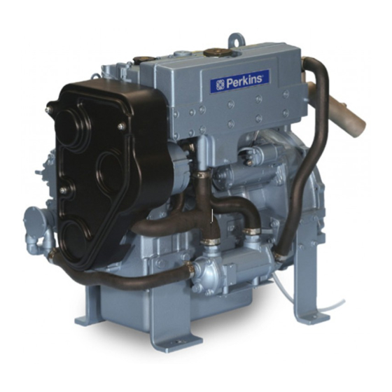
Page 23: Engine Views
N39453 Chapter 2 Engine views Introduction Perkins engines are built for specific applications and the views which follow do not necessarily match your engine specification. Page 15... -
Page 24: Location Of Engine Parts - 415Gm
Chapter 2 N39453 Location of engine parts - 415GM Front and right side view (A) Coolant filler cap Front lifting bracket Belt cover Oil filler cap Raw water pump Fuel inlet Excess fuel return Sump drain take-off point Oil pressure switch/sender 10. -
Page 25: Rear And Left Side View (B) - 415Gm
N39453 Chapter 2 Rear and left side view (B) - 415GM 15. Air filter 16. Exhaust 17. Starter Motor 18. Raw water cooler 19. Alternator 20. Coolant header tank / cooled exhaust manifold Page 17... -
Page 26: Location Of Engine Parts For The - 422Gm
Chapter 2 N39453 Location of engine parts for the - 422GM Front and left side view (C) Coolant header tank / cooled exhaust manifold Exhaust Starter motor Alternator Raw water cooler Raw water pump Belt cover Coolant filler cap Page 18... -
Page 27: Rear And Right Side View (D) - 422Gm
N39453 Chapter 2 Rear and right side view (D) - 422GM Oil filler cap 10. Front lifting bracket 11. Dipstick 12. Oil filler cap 13. Oil pressure switch/sender 14. Oil filter 15. Fuel inlet 16. Excess fuel return 17. Sump drain take-off point 18. -
Page 28: Location Of Engine Parts For The - 422Tgm
Chapter 2 N39453 Location of engine parts for the - 422TGM Front and right side view (E) Coolant filler Front lifting bracket Belt cover Oil filler cap Air filter kit (supplied loose) Raw water pump Solenoid, negative earth Fuel inlet Excess fuel return 10. -
Page 29: Rear And Right Side View (F) - 422Tgm
N39453 Chapter 2 Rear and right side view (F) - 422TGM 16. Coolant header tank / cooled exhaust manifold 17. Exhaust elbow 18. Starter motor 19. Raw water cooler 20. Alternator Page 21... -
Page 30: Location Of Engine Parts - 4.4Gm
Chapter 2 N39453 Location of engine parts - 4.4GM Front and left side view (G) of the engine Fresh water filler cap Air filter Oil filler cap 10. Electric fuel pump Header tank 11. Fuel filter canister Fresh water pump 12. -
Page 31: Rear And Right Side View (H) Of The Engine
N39453 Chapter 2 Rear and right side view (H) of the engine 16. Rear lifting eye 17. Air filter 18. Exhaust manifold 19. Starter 20. Lubricating oil sump 21. Front lifting eye 22. Alternator 23. Exhaust elbow Page 23... -
Page 32: Location Of Engine Parts - 4.4Tgm
Chapter 2 N39453 Location of engine parts - 4.4TGM Front and right side view (I) of the engine Air cleaner Oil filler cap Alternator Turbocharger Exhaust elbow Starter Lubricating oil sump Fresh water filler cap Front lifting eye 10. Exhaust manifold 11. -
Page 33: Rear And Left Side View (J) Of The Engine
N39453 Chapter 2 Rear and left side view (J) of the engine 13. Electric fuel pump 14. Fuel filter canister 15. Fresh water pump 16. Oil filler cap 17. Heat exchanger 18. Raw water pump 19. Dipstick 20. Oil filter 21. -
Page 34: Location Of Engine Parts - 4.4Twgm And 4.4Tw2Gm
Chapter 2 N39453 Location of engine parts - 4.4TWGM and 4.4TW2GM Front and left side view (K) of the engine Rear lifting eye Fresh water filler cap Header tank Fresh water pump Oil filler cap Belt cover Fuel return hose Air cleaner Electric fuel pump 10. -
Page 35: Rear And Right Side View (L) Of The Engine
N39453 Chapter 2 Rear and right side view (L) of the engine 17. Aftercooler 18. Turbocharger 19. Lubricating oil sump 20. Air filter 21. Exhaust manifold 22. Alternator 23. Exhaust elbow 24. Starter Page 27... -
Page 36: Location Of Engine Parts - 4.4Gm & 4.4Tgm Radiator
Chapter 2 N39453 Location of engine parts - 4.4GM & 4.4TGM Radiator Front and left side view (M) of the engine Fresh water filler cap Oil filler cap Radiator Fresh water pump Oil filler cap Fan guard Oil filter Air filter Electric fuel pump 10. -
Page 37: Rear And Right Side View (N) Of The Engine
N39453 Chapter 2 Rear and right side view (N) of the engine 13. Rear lifting eye 14. Air filter 15. Exhaust manifold 16. Starter 17. Lubricating oil sump 18. Front lifting eye 19. Thermostat (cylinder head) 20. Alternator 21. Exhaust elbow 22. -
Page 38: Location Of Engine Parts - 4.4Twgm And 4.4Tw2Gm Radiator
Chapter 2 N39453 Location of engine parts - 4.4TWGM and 4.4TW2GM Radiator Front and left side view (O) of the engine Fresh water filler cap Oil filler cap Radiator Oil filler cap Fan guard Oil filter Air filter Electric fuel lift pump Fuel filter canister 10. -
Page 39: Rear And Right Side View (P) Of The Engine
N39453 Chapter 2 Rear and right side view (P) of the engine 12. Rear lifting eye 13. Air filter 14. Exhaust manifold 15. Starter 16. Lubricating oil sump 17. Front lifting eye 18. Thermostat (cylinder head) 19. Exhaust elbow 20. Alternator 21. - Page 40 Chapter 2 N39453 Page 32...
-
Page 41: Operation Instructions
N39453 Chapter 3 Operation instructions Models - 415GM, 422GM & 422TGM, how to start the engine Several factors affect engine start, for example: • The power of the battery • The performance of the starter motor • The viscosity of the lubricating oil •... -
Page 42: How To Stop The Engine
The idle or the maximum speed settings must not be changed by the engine operator, because this can damage the engine or generator. The warranty of the engine can be affected if the seals on the fuel injection pump are broken during the warranty period by a person who is not approved by Perkins. Running-in A gradual running-in of a new engine is not necessary. -
Page 43: Models - 4.4Gm, 4.4Tgm, 4.4Twgm, 4.4Tw2Gm, 4.4Gm Rad, 4.4Tgm Rad, 4.4Twgm Rad & 4.4Tw2Gm Rad, Control Panel (Optional)
N39453 Chapter 3 Models - 4.4GM, 4.4TGM, 4.4TWGM, 4.4TW2GM, 4.4GM rad, 4.4TGM rad, 4.4TWGM rad & 4.4TW2GM rad, control panel (optional) Oil pressure gauge (A1) Shows engine oil pressure. The oil pressure will be greatest after a cold engine is started. If the gauge reading is fluctuating and the load has become stable, perform the following steps: •... - Page 44 Chapter 3 N39453 Temperature gauge (A2) Shows the engine water temperature. The engine should operate within the range of 78 C (172 F) to 90 (194 F). The temperature may vary according to load. However it should never exceed the boiling point for the pressurised system that is being used.
-
Page 45: Control Module (Optional)
N39453 Chapter 3 Control module (optional) The control panel (B) has six indicators (B3 to B8) that correspond to certain fault conditions. An indicator illuminates when the corresponding problem exists. Each indicator has a label that identifies the problem. The Engine Control Switch (B12) must be turned to the OFF/RESET position (B9) in order to turn off the indicators and to reset the control panel. -
Page 46: Engine Wiring Harness (Optional Equipment)
Chapter 3 N39453 Engine wiring harness (optional equipment) The engine wiring harness is designed to convey information to and from the engine control panel. Within the harness is a circuit breaker and a negative earth fuse to protect the wiring in the event of a short circuit as well as control relays. - Page 47 N39453 Chapter 3 Circuit diagram, engine wiring harness Information derived from 05-1013-1 Page 39...
- Page 48 Chapter 3 N39453 Standard DC circuits Information derived from 04-1006-1 Page 40...
-
Page 49: How To Start The Engine
N39453 Chapter 3 How to start the engine Use only this procedure to start the engine; it has been designed to protect the engine and the environment. Several factors can affect engine startup, for example: • The power of the batteries •... -
Page 50: How To Stop The Engine
Chapter 3 N39453 How to stop the engine Stopping the engine Cautions: • Stopping the engine immediately after it has been working under load can result in overheating and accelerated wear of the engine components. • If the engine has been running at high loads, run at low load for at least three minutes to reduce and stabalise the internal engine temperature before stopping the engine. -
Page 51: Emergency Procedures
N39453 Chapter 3 Emergency procedures If the engine stops Check that the fuel supply valve (if fitted) is in the open position. Check the fuel pre-filter (if fitted) and the fuel filters for water. If a warning light for water in the fuel is fitted, and it is illuminated, water has entered the pre-filter. - Page 52 Chapter 3 N39453 Page 44...
-
Page 53: Preventive Maintenance, Models
Chapter 4 Preventive maintenance, Models Preventive maintenance periods - 415GM, 422TGM & 422TGM These preventive maintenance periods apply to average conditions of operation. Check the periods given by the manufacturer of the boat in which the engine is installed. If necessary, use the shorter periods. When the operation of the engine must conform to the local regulations these periods and procedures may need to be adapted to ensure correct operation of the engine. -
Page 54: Schedules, Models - 415Gm, 422Gm & 422Tgm
Chapter 4 N39453 Schedules, models - 415GM, 422GM & 422TGM The schedules which follow must be applied at the interval (hours or months) which occur first. Every day or every 8 hours Every 2000 hours Every 500 hours or 12 months... -
Page 55: How To Drain The Coolant Circuit
Remove the drain plug (A1) from the cylinder block which is situated in the same place on all the engines and the drain plug from the heat exchanger, (B1) on the 415GM and (C1) on the 422GM/422TGM. Ensure that the drain holes are not restricted. Also, on the 422TGM, remove the drainplug on the raw water cooler (D1). -
Page 56: How To Check The Specific Gravity Of The Coolant
Chapter 4 N39453 How to check the specific gravity of the coolant For mixtures which contain inhibited ethylene glycol: Operate the engine until it is warm enough to open the thermostat. Continue to run the engine until the coolant has circulated through the cooling system. Stop the engine. -
Page 57: How To Drain The Raw Water System
“Coolant specification” for details of the correct coolant to be used. Ensure that the seacock is closed. Remove the drain plug on the 415GM and 422GM (F1) or 422TGM (G1) from the raw water cooler. After the system has been drained, refit the drain plug. -
Page 58: How To Check The Impeller Of The Raw Water Pump
Chapter 4 N39453 How to check the impeller of the raw water pump Ensure that the seacock is closed. Release the four setscrews (H1) which fasten the end plate (H2) of the raw water pump and remove the plate and ‘O’ ring (H3). When the end plate of the raw water pump is removed, some raw water will flow from the pump. -
Page 59: How To Check The Drive Belt
How to adjust the belt tension Cautions: • The alternator is driven by a drive belt of a specific design. Use only a Perkins POWERPART drive belt. If this is not done, an early failure of the belt may occur. -
Page 60: How To Renew The Element Of The Fuel Filter
Warning! Discard the used element and fuel in a safe place and in accordance with local regulations. Caution: It is important that only the genuine Perkins parts are used. The use of wrong parts could damage the fuel injection equipment. -
Page 61: How To Renew An Atomiser
Renew the sealing washers (L1) and fit the leak-off pipe. Tighten the banjo bolts to 27 Nm (19.9 lbf ft) 2,7 kgf m. 10. Eliminate air from the fuel system. 11. Operate the engine and check for leakage of fuel and air. Illustration shows 422GM and 422TGM, 415GM is similar Page 53... -
Page 62: How To Eliminate Air From The Fuel System
Attempt to start the engine using the starter motor for a maximum of 15 seconds, wait for 30 seconds before trying again. If the hand primer does not work, turn the engine half to one revolution to ensure correct operation. Illustration shows 422GM and 422TGM, 415GM is similar. Page 54... -
Page 63: How To Renew The Lubricating Oil
Warning! Discard the used lubricating oil in a safe place and in accordance with local regulations. Illustration shows 422GM and 422TGM, 415GM is similar. Page 55... -
Page 64: How To Renew The Canister Of The Lubricating Oil Filter
• Do not fill the sump past the notch on the dipstick. • The canister contains a valve and special tube to ensure that lubricating oil does not drain from the filter. Therefore, ensure that the correct Perkins POWERPART canister is used. Page 56... -
Page 65: How To Renew The Engine Breather Assembly
N39453 Chapter 4 How to renew the engine breather assembly The breather assembly should be renewed every 2000 hours. Caution: Ensure that the components of the breather assembly are fitted in their correct position (R1 - R6). If they are incorrectly fitted, the engine may be damaged. 422TGM only - Undo the clip (R1) and detach the hose (R2). -
Page 66: How To Renew The Element Of The Air Filter - 415Gm And 422Gm
Chapter 4 N39453 How to renew the element of the air filter - 415GM and 422GM Release the hose clip (S1) and remove the air filter assembly (S2). Fit a new filter element. Tighten the hose clip. Page 58... -
Page 67: How To Renew The Element Of The Air Filter - 422Tgm
N39453 Chapter 4 How to renew the element of the air filter - 422TGM Release the three clips (T1) and remove the end cover (T2). Remove the filter element (T3). Fit a new filter element. The illustration shows the air filter fitted to customers alternator Page 59... -
Page 68: How To Set The Valve Tip Clearances - 415Gm
Chapter 4 N39453 How to set the valve tip clearances - 415GM Notes: • The valve tip clearance is checked with a feeler gauge between the top of the valve stem and the rocker lever (U), with the engine cold. The correct clearance for both the inlet and the exhaust valves is 0,20 mm (0.0078 in). -
Page 69: How To Set The Valve Tip Clearances - 422Gm And 422Tgm
N39453 Chapter 4 How to set the valve tip clearances - 422GM and 422TGM Notes: • The valve tip clearance is checked with a feeler gauge between the top of the valve stem and the rocker lever (W), with the engine cold. The correct clearance for both the inlet and the exhaust valves is 0,20 mm (0.0078 in). -
Page 70: Seacock Strainer
Specialist manufacturers will advise on the maintenance of these anodes. Supplementary tools A general tool kit and an on-board spares kit are available from your Perkins Distributor. It is recommended that the tools and other parts, listed below, are also retained on-board:... -
Page 71: Preventive Maintenance Periods - 4.4Gm, 4.4Tgm, 4.4Twgm, 4.4Tw2Gm, 4.4Gm Rad, 4.4Tgm Rad, 4.4Twgm Rad & 4.4Tw2Gm Rad
N39453 Chapter 4 Preventive maintenance periods - 4.4GM, 4.4TGM, 4.4TWGM, 4.4TW2GM, 4.4GM rad, 4.4TGM rad, 4.4TWGM rad & 4.4TW2GM rad. These preventive maintenance periods apply to average conditions of operation. Check the periods given by the manufacturer of the boat in which the engine is installed. If necessary, use the shorter periods. When the operation of the engine must conform to the local regulations these periods and procedures may need to be adapted to ensure correct operation of the engine. -
Page 72: Schedules - 4.4Gm, 4.4Tgm, 4.4Twgm, 4.4Tw2Gm
Chapter 4 N39453 Schedules - 4.4GM, 4.4TGM, 4.4TWGM, 4.4TW2GM. The schedules which follow must be applied at the interval (hours or months) which occur first. A First service at 25/50 hours D Every 500 hours or 12 months G Non-scheduled maintenance B Every day or every 8 hours E Every 1000 hours C Every 250 hours or 12 months... -
Page 73: Schedules - 4.4Gm Rad, 4.4Tgm Rad, 4.4Twgm Rad & 4.4Tw2Gm Rad
N39453 Chapter 4 Schedules - 4.4GM rad, 4.4TGM rad, 4.4TWGM rad & 4.4TW2GM rad. The schedules which follow must be applied at the interval (hours or months) which occur first. A First service at 25/50 hours D Every 500 hours or 12 months G Non-scheduled maintenance B Every day or every 8 hours E Every 1000 hours... -
Page 74: How To Fill The Coolant Circuit - 4.4Gm, 4.4Tgm, 4.4Twgm, 4.4Tw2Gm
Chapter 4 N39453 How to fill the coolant circuit - 4.4GM, 4.4TGM, 4.4TWGM, 4.4TW2GM. Warning! If coolant is to be added to the circuit during service, allow the engine to cool before the coolant is added. Remove the filler cap slowly as dangerous coolant could be discharged if the coolant is still hot and the system is under pressure. -
Page 75: How To Fill The Coolant Circuit - 4.4Gm Rad, 4.4Tgm Rad, 4.4Twgm Rad & 4.4Tw2Gm Rad
N39453 Chapter 4 How to fill the coolant circuit - 4.4GM rad, 4.4TGM rad, 4.4TWGM rad & 4.4TW2GM rad. Warning! If coolant is to be added to the circuit during service, allow the engine to cool before the coolant is added. -
Page 76: How To Drain The Coolant Circuit - 4.4Gm
Chapter 4 N39453 How to drain the coolant circuit - 4.4GM Warnings! • Do not drain the coolant while the engine is still hot and the system is under pressure because dangerous hot coolant can be discharged. • Discard used coolant in a safe place and in accordance with local regulations. Remove the filler cap of the coolant circuit (BB1). -
Page 77: How To Drain The Coolant Circuit - 4.4Tgm
N39453 Chapter 4 How to drain the coolant circuit - 4.4TGM Warnings! • Do not drain the coolant while the engine is still hot and the system is under pressure because dangerous hot coolant can be discharged. • Discard used coolant in a safe place and in accordance with local regulations. Remove the filler cap of the coolant circuit (EE1). -
Page 78: How To Drain The Coolant Circuit - 4.4Twgm & 4.4Tw2Gm
Chapter 4 N39453 How to drain the coolant circuit - 4.4TWGM & 4.4TW2GM Warnings! • Do not drain the coolant while the engine is still hot and the system is under pressure because dangerous hot coolant can be discharged. • Discard used coolant in a safe place and in accordance with local regulations. Remove the filler cap of the coolant circuit (HH1). -
Page 79: How To Drain The Coolant Circuit - 4.4Gm & 4.4Tgm Rad
N39453 Chapter 4 How to drain the coolant circuit - 4.4GM & 4.4TGM rad. Warnings! • Do not drain the coolant while the engine is still hot and the system is under pressure because dangerous hot coolant can be discharged. •... -
Page 80: How To Drain The Coolant Circuit - 4.4Twgm & 4.4Tw2Gm Rad
Chapter 4 N39453 How to drain the coolant circuit - 4.4TWGM & 4.4TW2GM rad. Warnings! • Do not drain the coolant while the engine is still hot and the system is under pressure because dangerous hot coolant can be discharged. •... -
Page 81: Engines Fitted With Keel Coolers
N39453 Chapter 4 Engines fitted with keel coolers The coolant capacity and the method used to drain the coolant circuit of an engine connected to a keel cooler will vary in different applications. Use the instructions given by the keel cooler manufacturer to drain and renew the engine coolant when a keel cooler is fitted. -
Page 82: How To Drain The Raw Water System - 4.4Gm & 4.4Tgm
Chapter 4 N39453 How to drain the raw water system - 4.4GM & 4.4TGM Caution: The raw water system cannot be drained completely. If the system is drained for engine preservation purposes or for protection from frost, the system must be filled again with an approved antifreeze mixture. See “Coolant specification”... -
Page 83: How To Drain The Raw Water System - 4.4Twgm & 4.4Tw2Gm
N39453 Chapter 4 How to drain the raw water system - 4.4TWGM & 4.4TW2GM Caution: The raw water system cannot be drained completely. If the system is drained for engine preservation purposes or for protection from frost, the system must be filled again with an approved antifreeze mixture. See “Coolant specification”... -
Page 84: How To Check The Impeller Of The Raw Water Pump - 4.4Gm, 4.4Tgm, 4.4Twgm & 4.4Tw2Gm
Chapter 4 N39453 How to check the impeller of the raw water pump - 4.4GM, 4.4TGM, 4.4TWGM & 4.4TW2GM Ensure that the seacock is closed. Release the four setscrews which fasten the end plate of the raw water pump and remove the plate. When the end plate of the raw water pump is removed, some raw water will flow from the pump. -
Page 85: How To Check The Drive Belt - 4.4Gm, 4.4Tgm, 4.4Twgm & 4.4Tw2Gm
- 45N (10 lbf) 4,5 kgf - the correct deflection of the belt is 10 mm (3/8 in). How to adjust the belt tension Caution: The alternator is driven by a drive belt of a specific design. Use only a Perkins POWERPART drive belt. If this is not done, an early failure of the belt may occur. -
Page 86: How To Check The Drive Belt - 4.4Gm Rad, 4.4Tgm Rad, 4.4Twgm Rad & 4.4Tw2Gm Rad
How to adjust the belt tension Caution: The alternator is driven by a pair of drive belts of a specific design. Use only Perkins POWERPART drive belts. If this is not done, an early failure of the belts may occur. -
Page 87: How To Renew The Element Of The Fuel Filter - 4.4Gm, 4.4Tgm, 4.4Twgm & 4.4Tw2Gm
Warning! Discard the used canister and fuel oil in a safe place and in accordance with local regulations. Caution: It is important that only the genuine Perkins parts are used. The use of wrong parts could damage the fuel injection equipment. -
Page 88: How To Renew The Element Of The Fuel Filter - 4.4Gm Rad, 4.4Tgm Rad, 4.4Twgm Rad & 4.4Tw2Gm Rad
Warning! Discard the used canister and fuel oil in a safe place and in accordance with local regulations. Caution: It is important that only the genuine Perkins parts are used. The use of wrong parts could damage the fuel injection equipment. -
Page 89: Atomiser Maintenance
N39453 Chapter 4 Atomiser maintenance Atomiser faults Caution: A faulty atomiser must be renewed by a person who has had the correct training. Regular maintenance of the atomisers is not necessary. The atomiser nozzles should be renewed and not cleaned, and renewed only if an atomiser fault occurs. Some of the problems that may indicate that new nozzles are needed are listed below: •... -
Page 90: How To Remove And To Fit An Atomiser
Chapter 4 N39453 How to remove and to fit an atomiser How to remove Warning! The combustible material of some components of the engine (for example certain seals) can become extremely dangerous if it is burned. Never allow this burnt material to come into contact with the skin or with the eyes. -
Page 91: How To Fit
N39453 Chapter 4 How to fit Remove all covers and caps from the component and connections. Put a new seat washer into the seat recess in the cylinder head. Note: Some new atomiser’s have the seat washer (AG3) fitted on the atomiser. Ensure that the atomiser seal is not damaged. -
Page 92: How To Eliminate Air From The Fuel System
Chapter 4 N39453 How to eliminate air from the fuel system Cautions: • Under no circumstances should any attempt be made to remove the electric fuel lift pump from the filter head as it is not a serviceable item. • Do not operate the engine until the air is eliminated from the fuel injection pump. •... -
Page 93: How To Renew The Lubricating Oil
N39453 Chapter 4 How to renew the lubricating oil Warning! Discard the used lubricating oil in a safe place and in accordance with local regulations. Warning! Do not adjust the oil level while running. Note: Renew the filter canister when the lubricating oil is renewed. Drain the lubricating oil into a suitable container with a capacity of approximately 10 litres (17.5 pints), the lubricating oil should be drained while it is still hot. -
Page 94: How To Renew The Canister Of The Lubricating Oil Filter
• Do not fill the sump past the full mark on the dipstick. • The canister contains a valve and special tube to ensure that lubricating oil does not drain from the filter. Therefore, ensure that the correct Perkins POWERPART canister is used. Page 86... -
Page 95: Air Filter
N39453 Chapter 4 Air filter Caution: Do not operate the engine if there is a blockage in the air filter or the induction hose. This can cause lubricating oil to enter the cylinders through the breather valve. Environmental conditions have an important effect on the frequency at which the air filter needs service. Air filters have automatic dust valves (AM1) through which dust is expelled from the filter. -
Page 96: Restriction Indicator
Chapter 4 N39453 Restriction indicator The restriction indicator is fitted on the air filter outlet or between the air filter and the induction manifold. When the red warning indicator (AO1) is seen through the clear panel (AO2) after the engine has stopped, the air filter element must be removed for service. -
Page 97: How To Check The Valve Tip Clearances
N39453 Chapter 4 How to check the valve tip clearances The valve tip clearances are checked between the top of the valve stem and the rocker lever (AP), with the engine cold. The correct clearance for inlet valves is 0,20 mm (0.008 in) and 0,45 mm (0.018 in) for exhaust valves. -
Page 98: Supplementary Tools
N39453 Supplementary tools A general tool kit and an on-board spares kit are available from your Perkins distributor. It is recommended that the tools and other parts, listed below, are also retained on-board: Wire, 20 SWG (1 mm in diameter) -
Page 99: Engine Fluids
If you need advice on adjustments to an engine setting or to the lubricating oil change periods which may be necessary because of the standard of the available fuel, consult your nearest Perkins distributor or Wimborne Marine Power Centre. -
Page 100: Lubricating Oil Specification
Chapter 5 N39453 Lubricating oil specification Use only a good quality lubricating oil that is not less than the specification API-CG4/CH4 or ACEA-E3/E5. Caution: The type of lubricating oil to be used may be affected by the quality of the fuel which is available. For further details, see “Fuel specification”. -
Page 101: Coolant Specification
N39453 Chapter 5 Coolant specification The quality of the coolant which is used can have a great effect on the efficiency and life of the cooling system. The recommendations indicated below can help to maintain a good cooling system and to protect it against frost and/or corrosion. - Page 102 Chapter 5 N39453 Page 94...
-
Page 103: Fault Diagnosis
N39453 Chapter 6 Fault diagnosis Problems and possible causes Engine problem Possible causes Checks by the user Checks by the workshop personnel The starter motor turns the engine too slowly 1, 2, 3, 4 The engine does not start 5, 6, 7, 8, 9, 10, 12, 13, 14, 34, 35, 36, 37, 38, 42, 15, 17 43, 44... -
Page 104: List Of Possible Causes
Chapter 6 N39453 List of possible causes 44. Piston rings are not free or they are worn or broken. 1. Battery capacity low. 45. Valve stems and/or guides are worn. Bad electrical connections. 46. Crankshaft bearings are worn or damaged. Fault in starter motor. -
Page 105: Engine Preservation
Use these procedures after the engine is withdrawn from service. The instructions for the use of POWERPART products are given on the outside of each container. Procedure models - 415GM, 422GM, 422TGM, 4.4GM, 4.4TGM, 4.4TWGM & 4.4TW2GM Completely clean the outside of the engine. -
Page 106: How To Add Coolant To The Raw Water System For Engine Preservation Purposes
18. If the engine protection is done correctly according to the above recommendations, no corrosion damage will normally occur. Perkins are not responsible for damage which may occur when an engine is in storage after a period in service. -
Page 107: Procedure Models - 4.4Gm Rad, 4.4Tgm Rad, 4.4Twgm Rad & 4.4Tw2Gm Rad
If the engine protection is done correctly according to the above recommendations, no corrosion damage will normally occur. Perkins or Wimborne Marine Power Centre are not responsible for damage which may occur when an engine is in storage after a period in service. - Page 108 Chapter 7 N39453 Page 100...
-
Page 109: Parts And Service
Parts and service Introduction If problems occur with your engine or with the components fitted onto it, your Perkins distributor can make the necessary repairs and will ensure that only the correct parts are fitted and that the work is done correctly. - Page 110 Chapter 8 N39453 POWERPART Metal repair putty Designed for external repair of metal and plastic. Part number 21820126. POWERPART Pipe sealant and sealant primer To retain and seal pipe connections with coarse threads. Pressure systems can be used immediately. Part number 21820122. POWERPART Radiator stop leak For the repair of radiator leaks.
-
Page 111: General Data
N39453 Chapter 9 General data 415GM Number of cylinders............................3 Cylinder arrangement ..........................In line Cycle..............................Four stroke Induction system:........................Naturally aspirated Combustion system ........................Indirect injection Nominal bore ..........................84,0 mm (3.31 in) Stroke .............................90,0 mm (3.54 in) Compression ratio ............................22.5:1 Cubic capacity ............................1496cc Firing order ...............................1, 2, 3... -
Page 112: 422Gm
Chapter 9 N39453 422GM Number of cylinders............................4 Cylinder arrangement ..........................In line Cycle..............................Four stroke Induction system:........................Naturally aspirated Combustion system ........................Indirect injection Nominal bore ..........................84,0 mm (3.31 in) Stroke ...........................100,0 mm (3.94 in) Compression ratio ............................23.3:1 Cubic capacity ............................2216 cc Firing order ............................1, 3, 4, 2 Valve tip clearances (cold) ....................0,20 mm (0.0078 in) Lubricating oil pressure (maximum engine... -
Page 113: 422Tgm
N39453 Chapter 9 422TGM Number of cylinders............................4 Cylinder arrangement ..........................In line Cycle..............................Four stroke Induction system:..........................Turbocharged Combustion system ........................Indirect injection Nominal bore ..........................84,0 mm (3.31 in) Stroke ...........................100,0 mm (3.94 in) Compression ratio ............................23.3:1 Cubic capacity ............................2216 cc Firing order ............................1, 3, 4, 2 Valve tip clearances (cold) ....................0,20 mm (0.0078 in) Lubricating oil pressure (maximum engine speed and normal engine temperature) ............200 kPa (29 lbf/in... - Page 114 Chapter 9 N39453 4.4GM Number of cylinders............................4 Cylinder arrangement ..........................In line Cycle..............................Four stroke Induction system........................Naturally aspirated Combustion system ........................Direct injection Nominal bore ........................105,00 mm (4.13 in) Stroke ...........................127,0 mm (5.00 in) Compression ratio ............................19.3:1 Cubic capacity ........................4,4 litres (269.00 in Firing order ............................1, 3, 4, 2 Valve tip clearances (hot or cold) Inlet ............................0,20 mm (0.008 in)
-
Page 115: 4.4Tgm
N39453 Chapter 9 4.4TGM Number of cylinders............................4 Cylinder arrangement ..........................In line Cycle..............................Four stroke Induction system...........................Turbocharged Combustion system ........................Direct injection Nominal bore ........................105,00 mm (4.13 in) Stroke ...........................127,0 mm (5.00 in) Compression ratio ............................18.3 Cubic capacity ........................4,4 litres (269.00 in Firing order ............................1, 3, 4, 2 Valve tip clearances (hot or cold) Inlet ............................0,20 mm (0.008 in) -
Page 116: 4.4Twgm
Chapter 9 N39453 4.4TWGM Number of cylinders............................4 Cylinder arrangement ..........................In line Cycle..............................Four stroke Induction system......................Turbocharged/aftercooled Combustion system ........................Direct injection Nominal bore ........................105,00 mm (4.13 in) Stroke ...........................127,0 mm (5.00 in) Compression ratio ............................19.3 Cubic capacity ........................4,4 litres (269.00 in Firing order ............................1, 3, 4, 2 Valve tip clearances (hot or cold) Inlet ............................0,20 mm (0.008 in) -
Page 117: 4.4Tw2Gm
N39453 Chapter 9 4.4TW2GM Number of cylinders............................4 Cylinder arrangement ..........................In line Cycle..............................Four stroke Induction system......................Turbocharged/aftercooled Combustion system ........................Direct injection Nominal bore ........................105,00 mm (4.13 in) Stroke ...........................127,0 mm (5.00 in) Compression ratio ............................19.3 Cubic capacity ........................4,4 litres (269.00 in Firing order ............................1, 3, 4, 2 Valve tip clearances (hot or cold) Inlet ............................0,20 mm (0.008 in) -
Page 118: 4.4Gm Radiator
Chapter 9 N39453 4.4GM Radiator Number of cylinders............................4 Cylinder arrangement ..........................In line Cycle..............................Four stroke Induction system........................Naturally aspirated Combustion system ........................Direct injection Nominal bore ........................105,00 mm (4.13 in) Stroke ...........................127,0 mm (5.00 in) Compression ratio ............................19.3:1 Cubic capacity ........................4,4 litres (269.00 in Firing order ............................1, 3, 4, 2 Valve tip clearances (hot or cold) Inlet ............................0,20 mm (0.008 in) -
Page 119: 4.4Tgm Radiator
N39453 Chapter 9 4.4TGM Radiator Number of cylinders............................4 Cylinder arrangement ..........................In line Cycle..............................Four stroke Induction system...........................Turbocharged Combustion system ........................Direct injection Nominal bore ........................105,00 mm (4.13 in) Stroke ...........................127,0 mm (5.00 in) Compression ratio .............................18.23 Cubic capacity ........................4,4 litres (269.00 in Firing order ............................1, 3, 4, 2 Valve tip clearances (hot or cold) Inlet ............................0,20 mm (0.008 in) -
Page 120: 4.4Twgm Radiator
Chapter 9 N39453 4.4TWGM Radiator Number of cylinders............................4 Cylinder arrangement ..........................In line Cycle..............................Four stroke Induction system......................Turbocharged/aftercooled Combustion system ........................Direct injection Nominal bore ........................105,00 mm (4.13 in) Stroke ...........................127,0 mm (5.00 in) Compression ratio .............................18.23 Cubic capacity ........................4,4 litres (269.00 in Firing order ............................1, 3, 4, 2 Valve tip clearances (hot or cold) Inlet ............................0,20 mm (0.008 in) -
Page 121: 4.4Tw2Gm Radiator
N39453 Chapter 9 4.4TW2GM Radiator Number of cylinders............................4 Cylinder arrangement ..........................In line Cycle..............................Four stroke Induction system......................Turbocharged/aftercooled Combustion system ........................Direct injection Nominal bore ........................105,00 mm (4.13 in) Stroke ...........................127,0 mm (5.00 in) Compression ratio .............................18.23 Cubic capacity ........................4,4 litres (269.00 in Firing order ............................1, 3, 4, 2 Valve tip clearances (hot or cold) Inlet ............................0,20 mm (0.008 in) - Page 122 Chapter 9 N39453 Page 114...
- Page 123 California Proposition 65 Warning Diesel engine exhaust and some of its constituents are known to the State of California to cause cancer, birth defects, and other reproductive harm.
- Page 124 Wimborne Marine Power Centre subsequently. 22 Cobham Road, Part No. N39453 issue 7 Ferndown Industrial Estate, Produced in England ©2013 by Wimborne Wimborne, Dorset, BH21 7PW, England. Marine Power Centre Tel: +44 (0)1202 796000, Fax: +44 (0)1202 796001 E-mail: Marine@Perkins.com Web: www.perkins.com/Marine...
Need help?
Do you have a question about the 415GM and is the answer not in the manual?
Questions and answers