mru MGAprime User Manual
Hide thumbs
Also See for MGAprime:
- User manual (126 pages) ,
- User manual (8 pages) ,
- User manual (44 pages)
Table of Contents
Advertisement
Quick Links
Advertisement
Table of Contents

Related Manuals for mru MGAprime


Summary of Contents for mru MGAprime
- Page 1 MGAprime USR MANUAL 9452EN-PR...
- Page 2 USER MANUAL MGAprime Producer: Legal notices / Intellectual property rights comments Original user manual © 2021 by MRU No part of this manual my be published in any form (print, photocopy, electronic media or any other publication form) without a written approval by the publisher.
-
Page 3: Table Of Contents
USER MANUAL MGAprime Table of Contents Information for product and safety ..........7 1.1. Safety manual ....................7 1.2. Safety precautions ..................7 Introduction ..................8 2.1. Intended use ....................8 2.2. About us ......................9 Description ..................11 3.1. - Page 4 USER MANUAL MGAprime 5.5. Operating the analyser in the extended temperature range ..32 Precautions for use in the extended temperature range ..... 32 Connecting heating box .................. 32 5.6. Operating analyser with NiHM-Battery ..........34 Measurement .................. 35 6.1.
- Page 5 USER MANUAL MGAprime 8.1. History ......................64 8.2. System extensions ..................65 8.3. Connections ....................66 8.4. Setting Date / Time ..................66 8.5. Programs ....................... 66 8.6. Instrument leak test ................... 67 8.7. Default settings ................... 68 8.8. Internal log Settings .................. 68 Copying all log data ..................
- Page 6 USER MANUAL MGAprime Appendix ..................91 13.1. Error diagnosis regarding the measuring instrument ....91 13.2. Switching off the analyser in case error ..........92 13.3. RS485 Extern (Option) ................93 13.4. Screw adapter onto HPI-Probe (Option) ..........94 13.5. Connecting analyser with MRU4win ............ 94 Connecting analyser with MRU4win via serial interface (RS 485).
-
Page 7: Information For Product And Safety
USER MANUAL MGAprime Information for product and safety 1.1. Safety manual All general information and safety precautions of MRU products are listed in the supplied separate safety manual. Therefore, this manual must be read and observed before the first use of the instrument . -
Page 8: Introduction
USER MANUAL MGAprime Introduction • This manual enables you to understand and safely operate this MRU Analyzer MGAprime. • Please read this manual with great vigilant and get familiar with the product before using it. • This analyser may only be operated by competent personnel and for its intended use. -
Page 9: About Us
(NO2). 2.2. About us The analyser is produced by the MRU GmbH in Neckarsulm, Germany (Founded in 1984), a medium sized company that is specialised in developing, producing and marketing high quality emission monitoring analysers. - Page 10 USER MANUAL MGAprime MRU GmbH Fuchshalde 8 + 12 74172 Neckarsulm - Obereisesheim GERMANY Tel +49 71 32 99 62 0 (Front office) Tel +49 71 32 99 62 61 (Service) Fax +49 71 32 99 62 20 Email: info@mru.de Site: www.mru.eu...
-
Page 11: Description
USER MANUAL MGAprime Description 3.1. Task The main task of the analyser is to analyse flue gases, as they are emitting from incinerators or engines. • The analyser is optimized for this purpose and includes all components from the gas sampling probe to data processing. - Page 12 USER MANUAL MGAprime Fresh air inlet Sample gas inlet Condensate outlet Diff. Pressure connector Vent collection box Vent outlet Sample gas filter (PTFE) Dust filter Auto-zero solenoid valve Sample gas pump Double stage gas cooler Sample flow sensor Paramagnetic sensor...
-
Page 13: The Analyser
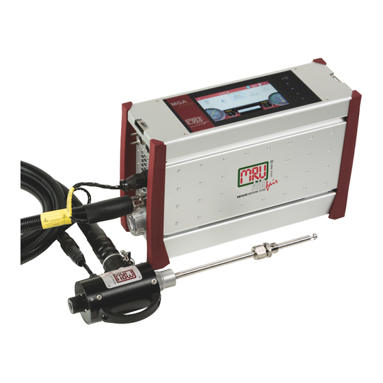
USER MANUAL MGAprime 3.3. The Analyser The analyser consists of a compact and robust metal housing with shock-absorbing rubber corners. All electrical and pneu- matic connections are located on the both front sides of the instrument. It is operated exclusively via the touch-sensitive touch screen. -
Page 14: Connectors
USER MANUAL MGAprime 3.4. Connectors Front side right Loudspeaker Ethernet (LAN) USB socket Second USB socket (option) RS485 (Option) Analog outputs 4 ... 20 mA Analog-inputs 4 … 20 mA Mains power supply Front side left Sample gas filter Condensate outlet port... -
Page 15: Probes
USER MANUAL MGAprime The connection drawings are also displayed in the menu Extras. ► Touch the menu Extras. A selection list appears. ► Press „Connections“. The left side of the analyser appears. ► Push „Right >>“. The right side of the analyser appears. -
Page 16: Heated Gas Sampling Probe
USER MANUAL MGAprime 3.6. Heated Gas sampling probe For interchangeable probe tube with flue gas temperature measure- ment using type K-thermoelement. Probe handle Probe tube Fast locking coupling Probe cone Cable plug (14-pin) Heated hose line Cable coupler (5-pin) Fast locking coupling Filter lock ►... - Page 17 USER MANUAL MGAprime ATTENTION When measuring with coiled heated hose line, the hose line is destroyed due to strong heat development. ► Roll out the heated hose line completely for each measurement. NOTE Please note that heating hoses with 110V and 230V are offered.
-
Page 18: Unheated Gas Sampling Probe
USER MANUAL MGAprime 3.7. Unheated Gas sampling probe Filter lock Fast locking coupling Cable coupler (5-pin) Cable plug (14-pin) Fast locking coupling Unheated hose line Probe cone Probe tube Probe handle ► Check the probe filter before and after every measurement. -
Page 19: Gas Supply
USER MANUAL MGAprime Optionally, connect a hose (DN 4/6) to the condensate drain. A hose (DN 4/6, not longer than 5 m) can also be connected to the sample gas outlet for discharge. For subsequent filtering, a round filter is used on the front of the Analyze. -
Page 20: Acid Injection
USER MANUAL MGAprime 3.11. Acid injection CAUTION Phosphoric acid (10 %) Phosphoric acid (10 %) may cause burns. ► If you come into contact with acid, wash the area im- mediately using a lot of water. ► Note the safety data sheet for phosphoric acid (10%). -
Page 21: Operation
USER MANUAL MGAprime 4 Operation 4.1. Commissioning The analyser leaves the factory assembled and ready for use. ► Check the analyser regarding completeness and integrity. ► Connect the analyser to the mains. The analyser switches on. The operating system boots. -
Page 22: Charging The Battery
USER MANUAL MGAprime Power-on and reset Reserve Reserve LED display mains opera- tion/battery charging mode Reserve Current flow rate Current pump load Current temperatures heated hose Selected measuring pro- gram, e.g., Test or measure- ment program Current temperatures of Current temperatures of gas... -
Page 23: Switching On The Analyser
USER MANUAL MGAprime 4.4. Switching on the analyser ► Touch the ⏻ button (1) for 3 sec. minimum LED lights blue ► Release the ⏻ button (1). Analyzer runs up. 4.5. Switching off the analyser There are two possibilities to switch off the analyser. -
Page 24: Set The Analyser To Standby Mode
USER MANUAL MGAprime 4.7. Set the analyser to standby mode The analyser is protected in standby mode. You cannot take measurements in standby mode. The actuators, for example pumps and gas coolers, are switched off as far as possible. Note that NDIR is not switched off. After you have left the standby mode, the analyser will start up again. -
Page 25: Back To Homescreen / Back To Measure
USER MANUAL MGAprime 4.8. Back to homescreen / Back to measure As soon as the back button is displayed, you have the option to go back to the homescreen or go back to the measurement, from any window. ► Press for one second ... -
Page 26: Settings
USER MANUAL MGAprime Settings After the analyser has been inspected and is ready for start-up it can be switched on and personalized settings can be entered. These settings can be changed at any time. 5.1. Analyser settings In the Settings menu, some analyser pre-sets may be configured: ►... - Page 27 USER MANUAL MGAprime For an overview on all available options please refer to the company’s home page or sales representatives See also chapter Activate NDIR- Fastmode function, page 41. Temperature unit Change of unit Hold delay Time in which Analog outputs maintain...
-
Page 28: Setting Time And Date
USER MANUAL MGAprime Ref. temperature Calculation of the values for a standard state at reference temperature Language Select analyzer language. Heated probe temper- 120°C – Default 160 °C ature 180°C Intervall auto-zero [h] See also Chapter Automatic zero point, Page 38. -
Page 29: Measurement Program
USER MANUAL MGAprime Measurement program The measured value window can be freely set with regard to the displayed measured values. Further measuring programs The measurement window for gas analysis can be configured and adapted to your needs. The measuring window initially displays 12 measured values, by a scrolling gesture it will display more values. -
Page 30: Setting Zoom
USER MANUAL MGAprime You can replace the selected value field with the selected measured value. You can insert the selected measured value in place of the se- lected value field. The previously selected value field moves accordingly. ► Touch „replace“ or „insert“. - Page 31 USER MANUAL MGAprime ► Touch „Gas flow measurement“. A setting window appears. ► Change the desired parameters. ► Touch „CHOOSE UNITS“. A setting window appears. ► Change the desired unit. ► Go back. The change will be saved.
-
Page 32: Operating The Analyser In The Extended Temperature Range
USER MANUAL MGAprime 5.5. Operating the analyser in the extended temperature range With the option "Operation at extended temperature range" you can carry out measurements up to -15°. NOTE Note that measurements with a connected Acid Dosing Unit APE are not recommended because phosphoric acid can freeze at low temperatures. - Page 33 USER MANUAL MGAprime ► Screw the heating box onto the analyser (1). The spacer bolts have internal threads. ► Connect the heating box to the external power supply (3). ► Plug the external power supply into a power socket. Ensure that the heating box is supplied with power during the entire measurement.
-
Page 34: Operating Analyser With Nihm-Battery
USER MANUAL MGAprime 5.6. Operating analyser with NiHM-Battery ► Please note that the following information is only relevant for you if an optional NiHM-Battery is installed in your analyser. The NiHM-Battery is mounted in the analyser instead of a LiIon-Battery. -
Page 35: Measurement
USER MANUAL MGAprime Measurement 6.1. Prepare measurement CAUTION Acid from the condensate Acid burns may result from weakly acidic liquids from the condensate. ► If you come into contact with acid, wash the area im- mediately using a lot of water. -
Page 36: Operating Temperature
USER MANUAL MGAprime ► Use a test gas humidifier for measurements (see chapter Connecting Gas moisture bottle, Page 45 or see chapter Connecting Acid Dosing Unit APE, Page 46) to prevent the gas cooler from drying out due to dry test gas. For a short time, you can also use dry test gas (for about 15 minutes). -
Page 37: Opening The Transport Bag
USER MANUAL MGAprime Opening the transport bag NOTE Note that different transport bags are offered. A standard transport bag is offered, which is intended exclusively for the transport and not for the operation of the analyser. Optionally, an IP42 operating bag is available, which is designed for the operation of the analyser. -
Page 38: Repeated Zero Point
USER MANUAL MGAprime If the ambient air is contaminated during the last two minutes of zeroing, the zero point is extended by approx. three to ten minutes. If there is no serious zero point after the zero-point extension, a message appears in the display. -
Page 39: Use Last Valid Zero Point
USER MANUAL MGAprime ► Set the desired interval auto-zero [h] in the menu Settings. See also Chapter 5.1 Analyser settings, S.26. NOTE Please note that a manually initiated zeroing sets a new time point grid. This depends on the set interval auto- zero [h] in the menu Settings. -
Page 40: Select Source Zero Point (Gas)
USER MANUAL MGAprime NOTE Please note that for the O2 sensor, regardless of this setting, a zero point measurement is performed after each switch-on. Select Source zero point (gas) You can select whether zero-point gas is always sucked in via the fresh air inlet. -
Page 41: Activate Ndir-Fastmode Function
USER MANUAL MGAprime A window appears. ► Choose the desired option. The zero gas is sucked in either via the probe or the fresh air inlet. NOTE After switching on, the first zero point is always taken via the fresh air inlet. -
Page 42: Charging State Of The Battery
USER MANUAL MGAprime ► Confirm the message. A zero point measurement is performed. An icon appears in the display. After the zero point measurement the NDIR-Fastmode is acti- vated. Charging state of the battery The battery symbol in the display indicates approximately the remaining capacity of the battery. - Page 43 USER MANUAL MGAprime NOTE ► Always connect a collection container to the condensate output (9). ► Ensure that the collection container has a sufficient empty volume. ► Dispose of acidic condensate and phosphoric acid in accordance with national and, if necessary, local dis- posal guidelines.
-
Page 44: Attach Clip-On Filter
USER MANUAL MGAprime Attach clip-on filter If you operate the analyser without a heated hose, dirt may collect in the gas inlet. ► In this case, plug the supplied clip-on filter onto the gas inlet (12). Controlling Filters The filters (probe filter and round filter) must be checked before and after each measurement. -
Page 45: Connecting Gas Moisture Bottle
USER MANUAL MGAprime Connecting Gas moisture bottle NOTE Fresh air and dry test gas must always be humidified to prevent the gas cooler from drying out. To humidify the test gas you can, for example, connect a gas mois- ture bottle. If you are using an Acid Dosing Unit APE the humidification is replaced by the Acid Dosing Unit APE. -
Page 46: Connecting Acid Dosing Unit Ape
USER MANUAL MGAprime Connecting Acid Dosing Unit APE See also Chapter 3.11 Acid injection, Page 20. CAUTION Acid from the condensate Acid burns may result from weakly acidic liquids from the condensate. ► If you come into contact with acid, wash the area im- mediately using a lot of water. - Page 47 USER MANUAL MGAprime NOTE Always connect the collecting container. Please note that the volume of the supplied collecting container is sufficient for 2 hours of meas- uring operation. ► Empty the collecting container after two hours of measuring operation. ► Dispose of acidic condensate and phosphoric acid in accordance with national and, if necessary, local dis- posal guidelines.
-
Page 48: Perform Leak Test
USER MANUAL MGAprime Perform leak test The analyser device has an integrated leak test to check the tightness of the gas paths. ► Check all plug connections for correct fit. ► Check all hoses and hose connections (from the probe tip to the gas inlet of the analyser) for leaks. - Page 49 USER MANUAL MGAprime ► Press START LEAK TEST A message appears. ► Confirm with YES, that the APE tubes are removed. ► Seal the gas port. The leak test is performed. Or if the complete gas path is to be checked for leaks:...
-
Page 50: Take A Measurement
USER MANUAL MGAprime 6.2. Take a measurement Setting O2 reference and Fuel type ► Touch the menu „Measure“. The measurement window appears. ► Touch the „Context menu“(19). A selection list appears. ► Touch „O2ref / Fuel type“. A window appears. -
Page 51: Starting The Measurement
USER MANUAL MGAprime ► Set the desired CO threshold value. ► Touch “OK”. The setting is saved. The stored ppm value determines the CO shutdown threshold. If the measured value reaches this threshold, the second fresh air purge pump starts and the CO sensor is separated from the gas path by a valve. -
Page 52: Selecting Channels For Auto-Measurement
USER MANUAL MGAprime ► Choose the desired site. The measured values are stored. The measurement continues until you switch off the analyser. See also Chapter Recalling stored measurements, Page 60. Selecting channels for Auto-measurement You can log a maximum of eight channels simultaneously. - Page 53 USER MANUAL MGAprime ► Press a measurand that you want to replace. A window appears. ► Select the desired measurand. ► Press OK. The measurand is replaced. You have the possibility to display two measurands simultaneously as a curve.
- Page 54 USER MANUAL MGAprime ► Press the graphic symbol. A diagram appears. ► If necessary, touch to stop the graphical display. The measurement will be continued in the background. ► If necessary, touch to continue the graphical display. 54 / 104...
-
Page 55: Starting Auto-Measurement
USER MANUAL MGAprime Starting Auto-measurement You can record the measured values for a defined period and have them displayed graphically. ► Touch the menu Measure. The measurement window appears. ► Touch the “Context menu” (19). A selection list appears. - Page 56 USER MANUAL MGAprime The Auto-measurement starts automatically. The Auto-measurement ends automatically. A protocol of the Auto-measurement appears ► Press the graphic symbol. A diagram appears. ► If necessary, press the gear wheel symbol to display other measurands in graphical form.
-
Page 57: Stopping Auto-Measurement
USER MANUAL MGAprime 8.8See also Chapter Internal log Settings, Page 68. Stopping Auto-measurement The Auto-measurement can be stopped manually at any time. ► Touch the context menu (19) while the measurement is recorded. A selection list appears. ► Touch „Stop logging“... -
Page 58: Data Memory
USER MANUAL MGAprime Data memory 7.1. Organizing data memory Base of the data memory of the analyser is a set of sites stored in the instrument. Every site exists of a unique site number and 12 freely usa- ble text lines which can have, e.g., the address, customer name etc. -
Page 59: Changing Site Data
USER MANUAL MGAprime Changing site data ► Touch the menu Sites. A selection list appears. ► Select the desired site. A window appears. ► Change the desired data. ► Touch „STORE“. The changes are stored. 59 / 104... -
Page 60: Deleting Sites
USER MANUAL MGAprime Deleting sites ► Touch the menu Sites. A selection list appears. ► Select the desired site. A window appears. ► Touch „Delete“. The site is deleted. Recalling stored measurements Stored measurement can be displayed individually for each site. -
Page 61: Data Transfer Via Usb (Csv Export)
USER MANUAL MGAprime ► Touch „MEASUREMENTS“. A selection list appears. ► Touch the desired measurement. The measurement window appears. 7.3. Data transfer via USB (CSV export) The data exchange format is CSV. A character-separated values (CSV) file is a simple text format for a database table. The analyser uses a sem- icolon ‘;’... - Page 62 USER MANUAL MGAprime ► Insert a USB-stick into the analyser. ► Touch the menu Sites. A selection list appears. ► Select the desired site. A window appears. ► Touch „MEASUREMENTS“. The stored measurements are displayed. ► Select the desired measurements.
- Page 63 USER MANUAL MGAprime ► Open the CSV-File with Excel. (Do not use Dat-files files or internal Log-files) 63 / 104 MRU GmbH, D-74172 Neckarsulm...
-
Page 64: Extras
USER MANUAL MGAprime Extras 8.1. History ► Touch the menu Extras. A selection list appears. ► Touch „History“. A window appears. ► Touch „DATE“. A selection list appears. ► Choose the desired period time. The chosen time period is displayed graphically. -
Page 65: System Extensions
USER MANUAL MGAprime 8.2. System extensions You have the possibility to expand the analyser with options. For this you will receive an option file from the manufacturer. ► Copy the options file onto a USB stick. NOTE You can also save the option files in subfolders. The an- alyser will search the folder structure on the USB stick up to the second hierarchy level. -
Page 66: Connections
USER MANUAL MGAprime ► Select the desired Options. ► Press “LOAD CHECKED OPTIONS”. A message appears. ► Touch OK. The option was successfully set. 8.3. Connections You can view the connections on the display of the analyser See also chapter 3.4Connectors, Page 14. -
Page 67: Instrument Leak Test
USER MANUAL MGAprime ► Select the program you want to change the name for. A keybar appears. ► Enter the desired Program name. ► Exit the Extras menu. ► Touch Selected measuring program (8) See also Chapter 4.2 Operating panel, page 21. -
Page 68: Default Settings
USER MANUAL MGAprime 8.7. Default settings You can reset the analyser to factory default. NOTE Note that when the analyser is reset to the factory de- fault, all individual settings are lost. ► Touch the menu Extras. A selection list appears. -
Page 69: Copying Single Log Data
USER MANUAL MGAprime ► Touch „SERVICE:COPY INTERNAL LOGG TO USB STICK“. A window appears. The copy process is started. A Symbol appears in the Display. ► Touch „OK“: The directory [serial number] Logg was created on the USB-Stick. - Page 70 USER MANUAL MGAprime ► Touch „FILE BROWSER“. A selection list appears. ► Choose the desired log file. A window appears. The desired log file appears in the window. ► Touch „COPY TO EXTERN USB-STICK“. A window appears.
-
Page 71: Analog Output Setup (4 - 20 Ma)
USER MANUAL MGAprime The directory [serial number] Logg was created on the USB-Stick. The log files are saved in the directory [serial number]. After copying, the display shows "File(s) successfully copied". ► Touch „OK“. 8.9. Analog output setup (4 – 20 mA) There are 8 Analog outputs (4-20 mA) available. -
Page 72: Setting Lower / Higher Limit
USER MANUAL MGAprime ► Choose the desired measurrand. ► Touch “OK“. The measurand is assigned to the desired channel. Setting lower / higher limit NOTE Setting lower limit (4mA) This setting determines the lower end value, corre- sponding to 4 mA. If the measured value falls below the set value, the Analog output stops at 4 mA. -
Page 73: Setting Analog Outputs During Zeroing
USER MANUAL MGAprime ► Enter the desired values for the lower and higher limit. ► Touch „OK“. The lower and higher limit are assigned to the desired channel. ► Touch "Default" to set the default values for the lower and upper limits. -
Page 74: Pin Assignment Of The 4-20 Ma Interface (Analog In/Out)
USER MANUAL MGAprime ► Touch the menu Extras. A selection list appears. ► Touch „Analog output setup (4-20mA)“. A window appears. ► Scroll to "Output during zeroing" ► Touch the field. ► Choose the desired option. Pin assignment of the 4-20 mA interface (Analog IN/OUT) ►... -
Page 75: Connecting Analyser With Wifi (Wlan)
USER MANUAL MGAprime ► Choose the desired channel. A window appears. ► Enter the desired values. ► Go back. The values appear in the selection list. The incoming measurand is displayed. 8.11. Connecting analyser with WIFI (WLAN) ►... - Page 76 USER MANUAL MGAprime NOTE Press the button REFRESH if no WLAN connection is displayed. ► Select the desired WLAN-Connection. A window appears. ► Enter the WLAN password. ► Touch „OK“. A connection to the WLAN network is established.
-
Page 77: Getting Information About The Network
USER MANUAL MGAprime ► Use the displayed WLAN -IP for MRU4win (in this example 192.168.43.53). See also Chapter 13.5 Connecting analyser with MRU4win, Page 8.12. Getting information about the network ► Touch the menu Extras. A selection list appears. -
Page 78: Assigning A Fixed Ip Address
USER MANUAL MGAprime 8.13. Assigning a fixed IP address ► Touch the menu Extras. A selection list appears. ► Touch „Network“. A window appears. ► Set the switch to "Static IP is active". The fields for „IP-Adress/Subnetmask“, „Gateway“... -
Page 79: Serial Connectivity (Rs485/Usb)
USER MANUAL MGAprime ► Choose the desired option. The change takes effect after a restart 8.14. Serial connectivity (RS485/USB) You have a connection option to MRU4win via Bluetooth 8.15. Printing measurement results In the menu Printer, you can select the type of connection between an optional printer and the analyser. -
Page 80: Printing Current Measurement Results
USER MANUAL MGAprime Printing current measurement results ► Switch on the printer. ► Go to the menu Measurement. The measurement window appears. ► Touch the “Context menu” (19). A selection list appears. ► Touch „Print“. The measurement is printed out with a slight delay. - Page 81 USER MANUAL MGAprime ► Touch „MEASUREMENTS“. The stored measurements are displayed. ► Touch the desired measurement. The measurement window appears. ► Touch the context menu (19). A selection list appears. ► Touch „Print“. The measurement is printed out with a slight delay.
-
Page 82: Service Values
USER MANUAL MGAprime 8.16. Service values This screen displays a number of internal parameters and their values. In case of unexpected behaviour of the analyser it might be helpful to communicate those values to our worldwide service staff: https://www.mru.eu ► Touch the menu Extras. -
Page 83: Info
USER MANUAL MGAprime Info In the menu Info, version information and installed options can be viewed. ► Touch menu info. A window appears. ► Touch „INFO“. A window appears. ► Touch „OPTIONS“. A window appears. 83 / 104... -
Page 84: Maintenance And Cleaning
USER MANUAL MGAprime 10 Maintenance and cleaning 10.1. Cleaning and maintenance The analyser needs only low maintenance effort for long value preservation: CAUTION Acid from the condensate Acid burns may result from weakly acidic liquids from the condensate. ► If you come into contact with acid, wash the area im- mediately using a lot of water. -
Page 85: Simple Service Work
USER MANUAL MGAprime 11 Simple service work 11.1. Information of the analyser components Information about analyser components is helpful in case of service or inquiries. ► Touch A selection list appears. ► Choose the desired component of the analyser. - Page 86 USER MANUAL MGAprime A window appears. ► Touch „LOAD FROM USB-STICK“. The firmware is copied to the analyser. The button"PERFORM FIRMWARE UPDATE" becomes active when the copy process is complete. ► Touch „PERFORM FIRMWARE UPDATE“. The firmware is updated.
-
Page 87: Specifications
USER MANUAL MGAprime Specifications The technical data listed here may differ depending on the analyser configuration. • means: included in the standard scope of each analyser O means: optional possible, availability depends on device configuration 12.1. Specifications of NDIR technology... -
Page 88: Sensors For Oxygen, Temperatures And Pressure
USER MANUAL MGAprime 12.2. Sensors for Oxygen, Temperatures and Pressure Electrochemical Sensor Long Life Measuring Range 0 - 25 Vol.% Resolution 0,01 Vol.% Abs. Accuracy ± 0,25 Vol.% Response Time T90 < 40s Years expected lifetime at air 5 Years... -
Page 89: Calculated Values And Accessories
User Manual MGAprime Gas outlet (Vent port) • passiv 3 mm active (req for long VENT lines or Optional pressurized Vent) 12.4. Calculated values and accessories Measurement values available as mg/Nm Ref, mg/kWh NOX: mg/Nm Velocity based on differential pressure... -
Page 90: Technical Data Acid Dosing Unit Ape
USER MANUAL MGAprime Power supply (w/o heated 86 - 265 Vac / 47 - 63 Hz / 105 W sample line) Power consumption (with 5m 300 W typical heated sample line) (600 W max.) Weight unit w/ NDIR bench 10 kg... -
Page 91: Appendix
User Manual MGAprime Appendix 13.1. Error diagnosis regarding the measuring instrument Fault indication Possible causes Repair Gas cooler is faulty! Gas cooler faulty. Contact MRU service depart- The system will shut ment. down. Undervoltage!!! Battery is discharged. Connect instrument to power The System will shut grid. -
Page 92: Switching Off The Analyser In Case Error
USER MANUAL MGAprime Fault indication Possible causes Repair Condensate or wa- ► To continue the operation, it has to be en- ter has been de- sured that no water will be fed to the sen- tected behind the sors. gas cooler stage. To ►... -
Page 93: Rs485 Extern (Option)
L 32 bit signed integer value (-2.147.483.648…2.147.483.647) F 32 bit floating point value (reads -1E38, when not availa- ble)- Further information about the defined registers on demand (www.mru.eu) and on the device supplied USB stick! 93 / 104 MRU GmbH, D-74172 Neckarsulm... -
Page 94: Screw Adapter Onto Hpi-Probe (Option)
USER MANUAL MGAprime 13.4. Screw adapter onto HPI-Probe (Option) With the adapter you have the possibility to use heated probe tubes from other manufacturers. The adapter is available in 3/8-inch and 3/4-inch sizes. When screwing the adapter onto the HPI probe, pay attention to the size of your probe tube. -
Page 95: Connecting Analyser With Mru4Win Via Tcp/Ip Connection
User Manual MGAprime Please note that the Modbus slave ID is a consecutive number. If the number 1 is already assigned, assign "Modbus Slave ID" 2 etc. to the analyser. ► You can now create the analyser in MRU4win. See also Chapter Creating analyser in MRU4win, Page 96. -
Page 96: Creating Analyser In Mru4Win
USER MANUAL MGAprime If the number 1 is already assigned, assign "Modbus Slave ID" 2 etc. to the analyser. ► You can now create the analyser in MRU4win. See also Chapter Creating analyser in MRU4win, Page 96. Creating analyser in MRU4win Modbus devices are not automatically identified in MRU4win. - Page 97 User Manual MGAprime ► Choose “Name” A selection list appears. ► Choose “1113 Device”. ► Set "Slave ID" to 1. ► Note that the slave ID must match to the "Modbus Slave ID" of the analyser. For example, if the analyser has the "Modbus Slave ID" 2, the "Slave ID"...
- Page 98 USER MANUAL MGAprime ► Set under "General” a check mark at "Activate Modbus". ► Go to “Livemeasurements”. The analyser appears in the column of available analyzers. ► Click on the "Connect-Icon” The analyser is connected. 98 / 104...
-
Page 99: Remote Control Of The Analyser Device Via Vnc
User Manual MGAprime 13.6. Remote control of the analyser device via VNC Activate WLAN-Hotspot (android) ► Install VNC viewer ► ► Configure VNC viewer Connect to device ► Activate VNC on analyser ► ► Use remote control via Android device... -
Page 100: General Instructions For The Heated Hose Line
USER MANUAL MGAprime 13.7. General Instructions for the heated hose line For the save operation of the sample line it is important that it is in- stalled correctly. This includes the following points: • The bending radius as given below is maintained, •... -
Page 101: Bending Radius Of Heated Sampling Lines
User Manual MGAprime Bending radius of heated sampling lines The picture below shows the minimal bending radius. Bending radius min. = 32 ATTENTION Falling below the bending radius will reduce life time of the sampling probe. 101 / 104 MRU GmbH, D-74172 Neckarsulm... -
Page 102: Cxhy Calculation
USER MANUAL MGAprime 13.8. CxHy Calculation The calculation for CxHy is: • if CH and C are present: CxHy = CH • if only one HC - channel is available, CxHy is equal to it. 13.9. Spare parts Part number... -
Page 103: Declaration Of Conformity
User Manual MGAprime 14 Declaration of conformity 103 / 104 MRU GmbH, D-74172 Neckarsulm... - Page 104 USER MANUAL MGAprime 104 / 104 MRU GmbH, D-74172 Neckarsulm...
Need help?
Do you have a question about the MGAprime and is the answer not in the manual?
Questions and answers