Table of Contents
Advertisement
Advertisement
Table of Contents

Related Manuals for Art TubeFire 8


Summary of Contents for Art TubeFire 8
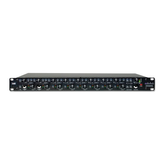
- Page 1 TubeFire 8™ 8 CHANNEL TUBE MIC-PREAMP SYSTEM USER’S GUIDE...
-
Page 2: Important Safety Instructions - Read First
IMPORTANT SAFETY INSTRUCTIONS – READ FIRST This symbol, wherever it appears, This symbol, wherever it appears, alerts alerts you to the presence of uninsulated you to important operating and maintenance dangerous voltage inside the enclosure. Voltage instructions in the accompanying literature. that may be sufficient to constitute a risk of shock. -
Page 3: Table Of Contents
Installing the Windows PC driver... 11 Using the Windows PC driver panel ... 11 Changing the name of your TubeFire 8™ with a Windows PC... 11 Changing the sample rate ... 12 Adjusting system latency with a Windows PC ... 14 Using the wordclock input with a Windows PC... - Page 4 FIGURE 12 - ART Panel program ... 17 FIGURE 13 - Audio/MIDI Setup - Audio pull-down menu ... 18 FIGURE 14 - Aggregate Device Editor window ... 18 FIGURE 15 - ART Card control panel for multiple TubeFire 8™ units ... 19...
-
Page 5: Introduction
AC Power Hookup The TubeFire 8 has an internal power supply. Only connect the unit to mains power of the type marked on the rear panel. The power source must provide a good ground connection, and the ground pin on the mains plug should never be defeated. -
Page 6: Firewire (Ieee 1394) (Sony Ilink ® ) Connections
Firewire (IEEE 1394) (Sony iLINK The TubeFire 8 has two 6 pin Firewire ports located on the rear panel. Both ports are identical, and can be used interchangeably. Use a quality Firewire cable to connect the TubeFire 8 to your computer. NOTE: Make all connections with both the Computer and TubeFire 8... -
Page 7: Instrument Input
These switches provide phantom power to each set of four XLR inputs. Use phantom power only when the microphone you are using requires it. Doing so will extend the life of the TubeFire 8 as well as reduce the possibility of a shock hazard. -
Page 8: Headphone / Line Mixer
Headphone / Line Mixer All of the sources selected for the output jacks of the TubeFire 8™ are mixed together to provide a signal for the Headphone/Line Mixer Output. Use the Output Source switches to select which channels are from the mic preamps and which channels are from the computer in the headphone output mix. -
Page 9: Rear Panel
When the switch is in the “out” position, the output levels are optimized for –10dBV systems. One way to determine how this switch should be set is to send audio through the TubeFire 8™ from a computer and run it into a line input on a mixer or signal processor. Check the meters on the mixer or signal processor to see if the level appears to be too high (clipping) or too low (barely showing any indication on the meters). -
Page 10: Hardware Operation
TubeFire 8™ and external gear. One way to determine how this switch should be set is to send audio through the TubeFire 8™ from a computer and run it into a line input on a mixer or signal processor. Check the meters on the mixer or signal processor to see if the level appears to be too high (clipping) or too low (barely showing any indication on the meters). -
Page 11: Figure 4 - Block Diagram
FIGURE 4 - Block Diagram... -
Page 12: Pc Software Operation
FIGURE 5 - Renaming your TubeFire 8™ The information is saved in the flash memory of the TubeFire 8™ and will be there for the PC driver even after the unit is powered off. (NOTE: The renaming function is not available for Mac operation.) -
Page 13: Changing The Sample Rate
Changing the sample rate STEP ONE: Open the ART Card Control panel on a PC, to modify the sample rate setting. STEP TWO: Change the sample rate setting in the recording software. In Cubase, this is done under the PROJECT tab in the PROJECT SETUP dialog. See FIGURE 7 for an example. -
Page 14: Figure 8 - Sample Rate Indication
ASIO Drop Outs number reduces to zero. NOTE: The front panel Sample Rate display on the TubeFire 8™ is a histogram. FIGURE 8 shows the display lit for a 48KHz sample rate. This makes reading the display much easier at a distance. ALL of the lights are lit when the unit is set to 96KHz. -
Page 15: Adjusting System Latency With A Windows Pc
Adjusting system latency with a Windows PC Adjusting the buffer depth varies the latency of the computer system used together with the TubeFire 8™. Typical recording software programs utilize either WDM or ASIO drivers. Adjusting the buffer depth control to the left will reduce the buffer size and therefore reduce the latency. -
Page 16: Using The Wordclock Input With A Windows Pc
Multiple TubeFire 8™ units can be daisy-chained by looping the wordclock signal from unit to unit, using the Wordclock Input and Thru jacks of each TubeFire 8™, and then placing a single 75 Ohm BNC terminator on the Wordclock Thru jack of the last device in the chain (furthest away from the wordclock generator). -
Page 17: Mac Software Operation
Run the AUDIO/MIDI setup utility to change the sample rate. Select properties for the device labeled “ART Firewire nnnn” (the “nnnn” refers to a unique serial number for each TubeFire 8™). Under the Audio Input section use the Format pull-down menu to select the desired sample rate. -
Page 18: Using The Wordclock Input With A Mac
Multiple TubeFire 8™ units can be daisy-chained by looping the wordclock signal from unit to unit, using the Wordclock Input and Thru jacks of each TubeFire 8™, and then placing a single 75 Ohm BNC terminator on the Wordclock Thru jack of the last device in the chain (furthest away from the wordclock generator). -
Page 19: Creating An Aggregate Device With A Mac
“Use” buttons. At this point you can re-name the Aggregate Device by double clicking the name. We used the name “ TubeFire 8™ pair” in our example in Figure 14. Click Done and you can use the new device! -
Page 20: Applications
FIGURE 15 - ART Card control panel for multiple TubeFire 8™ units These numbers are based on 100Mb/Sec. Firewire Rates. The TubeFire 8™ is capable of 400Mb/s, but there are a number of factors that may limit your system to the 100Mb/Sec. rate. -
Page 21: Typical Applications
Wordclock should to be applied to EVERY unit in the audio chain including soundcards. The wordclock signal can be looped through the TubeFire 8™ units using their rear panel wordclock Input and Thru connectors, with a 75 Ohm BNC terminator applied to the last unit in the chain. -
Page 22: Warranty Information
WARRANTY INFORMATION Limited Warranty: Applied Research and Technology will provide warranty and service for this unit in accordance with the following warrants: Applied Research and Technology, (A R T) warrants to the original purchaser that this product and the components thereof will be free from defects in workmanship and materials for a period of three years from the date of purchase. -
Page 23: Service
SERVICE The following information is provided in the unlikely event that your unit requires service. 1) Be sure that the unit is the cause of the problem. Check to make sure the unit has the proper power supplied, all cables are connected correctly, and the cables themselves are in working condition. -
Page 24: Tubefire 8™ Specifications
Note: 0 dBu = 0.775V RMS, 0dBV = 1V RMS ART maintains a policy of constant product improvement. ART reserves the right to make changes in design or make additions to or improvements upon this product without any obligation to install the same on products previously manufactured. - Page 25 NOTES...
- Page 26 www.artproaudio.com E-mail: support@artproaudio.com © 2006 Applied Research & Technology 164-5004-201...
Need help?
Do you have a question about the TubeFire 8 and is the answer not in the manual?
Questions and answers